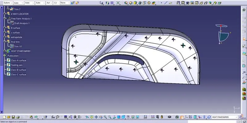
Week 9 - Project 1 - Door Trim Lower with Engineering Features
Door Trim Lower :
Darft analysis:
- Draft is a provide an angle to plastic component with cavity to reduce the friction .
- without having the draft it may causes the shape was resized .Output of a component is become unsatisfied.
- The minimum draft to any plastic component should be 2.5mm hence the class A surface of door trim lowyer is analysed for a draft..
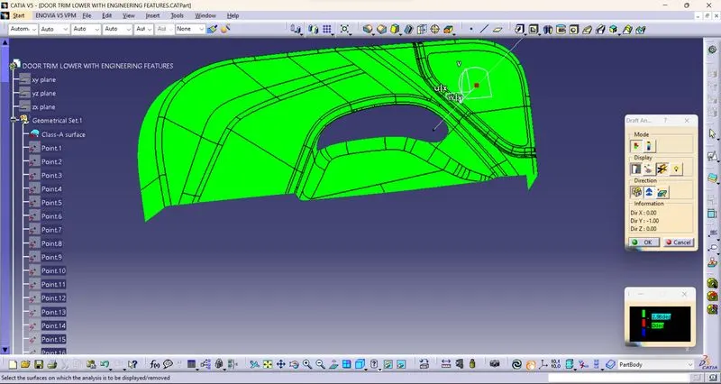
- The given classs A surface consists of hole we are to check it is not form so we have to check all views in which view it is visible then form a dummy line on the Flat surface along Y direction apply analysis.
- Hence in order to have minimum sidecore involvement and minimum cost we must have the tooling axis in line to the axis of the base at the surface centre.
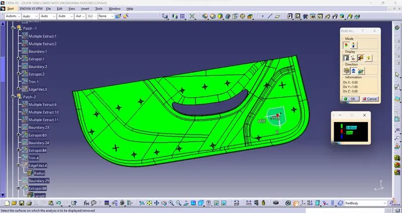
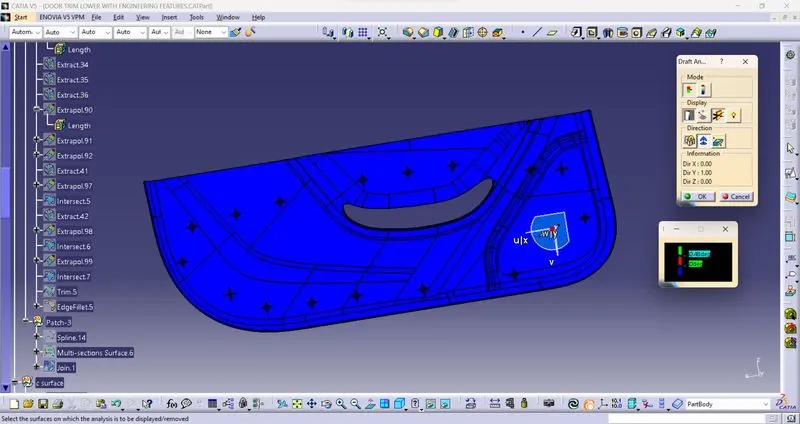
- Draft analysis can be done through tooling axis . select a compass on the draft analysis set on the tooling axis and lock it.
- Select the material option customized view parameters click ok.
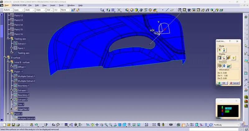
- click on the surface it will be visible as green in colour. Class A and Class C surface are in positive angle and Class B to be negative angle.
Tooling axis:
- Commonly we are consider holes in the class A surface than class A engineer was consider to construct a tooling axis from centre of the circle
- But here hole is in centre in a circle shape so we are consider to take a tooling axis but that tooling axis is not apply for the total area so we are decided a place a point on flat surface area.
- use point direction draw a line in y direction finally it is a final tooling axis.
- Use this tooling axis do the drafting analysis on the Class-A surface for intial and final conversion of solid surface draft analysis.
- Tooling axis can be form through Bisected method , Normal surface method,point direction method .
Construction:
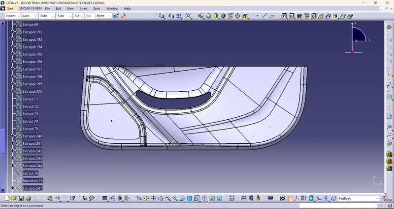
For every surface geometric set are to be added to choose easy to understand .
Body was in the part body.
Class -B surface:
- first we are offset the given class into down direction.
- Change the graphic colour to offset .three patches are appear.
- For the patch-1 extract the required surfaces and use multi extract with complementary mode remove the patches .
- unhide the extract area apply extrapolte the both surfaces and trim them apply filler on that trim area.
- For the patch -2 here we are extract the center surface and boundary faces also because after the trim it was not come easily so we are to use that as different extract.
- for the first extract unhide and extrapolate the bothe surfaces and trim them apply fillet on them .
- for boundary faces extrapolate the surfaces and apply trim it was not work so we use intersection command and check their is any gap if gap is their visible as black dots inthat area applu extrpolate and finally apply trim and give a filler for that area.
- For the patch-3 create a spline and use multisection surface command to clear the patch.
- Extrapolate the B surface on checking intersection with surface in the visibility of black dots for that area only extrapolate.
Class -C surface:
- select the outer boundary of the bumper as part by part for the front portion do with draft direction with 3degree angle as sweep and remaining surface was did with 90 degree with reference surface of sweep. For the curve position Form a point and create spline do multi section for that areas.
- For the centre hole also use sweep command with refernce surface with 90degrees to form a surface.
- If their is any gaps check with intersection command their any black points are visible are not.If visible to fill that surface.
- Join A +C
Final trim:
- Select joint of Class-C and Class -A trim with class -B to remove unwanted material finally of wanted object material was formed .
- For checking their any gaps in the surface to check use boundary to click on the surface its shows error means thier is no any gap.
After that Define part body with the command of closed surface in the part work bench to make a surface body into solid body.
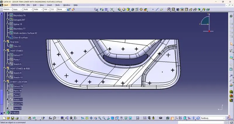
HEAT STAKES & RIBS:
3-2-1 PRINCIPLE:
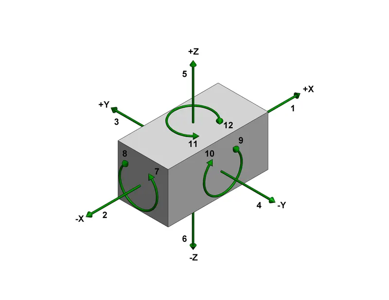
A work-piece free in space can move in an infinite number of directions. For analysis, this motion can be broken down into 12 directional movements or "degrees of freedom". All 12 degrees of freedom must be restricted to ensure proper referencing of a work-piece.
As shown in Fig 1, the 12 degrees of freedom all relate to the central axis of the work-piece. Notice the 6 axial degrees and 6 radial degrees of freedom. The axial degrees of freedom permit straight-line movement in both directions along the 3-principle axis shown as X, Y & Z. The radial degrees of freedom permit rotational movement, in both clockwise & counter clockwise radial directions around the same three axes.
Maintain the distace between tthe heatstakes are 50-55mm minimum has to be maintain.
- HEAT STAKES:
- Extract the surface create a point as 0 and create a plane through parallel through point .
- Use positioned sketch give a plane as reference and point as project point .
- Create a circle as diameter of 7 and 5 and pad it as 20mm up and 10mm as below for trrim purpose.
- Give a draft for outer and inner phase of stake as 0.5degree and neutral axis as plane and pulling direction is tooling axis.
RIBS:
- Create a sketch take a plane and point from stakes and create a line up and below coincide and constrained them.
- create a body and pad it distance are 6mm for aboce and below as 10mm as same as stake thickness as 1mm as neutral fiber.
- use draft command draft the phases of a rib and take neutral axis as plane and pulling direction is tooling axis .
- Give a fillet as 0.25mm for all sides of a ribs
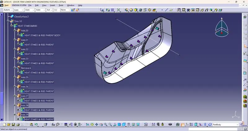
- union trim with heatstakes.
- Copy the heat stakes and ribs define the part body paste as special link use tranlate coomand to form a body at differnen point .
- Same process can be done at different point as translate.
- This all are add in body than union trim with main part body.
- Check with draft analysis as 0.48 it was done.
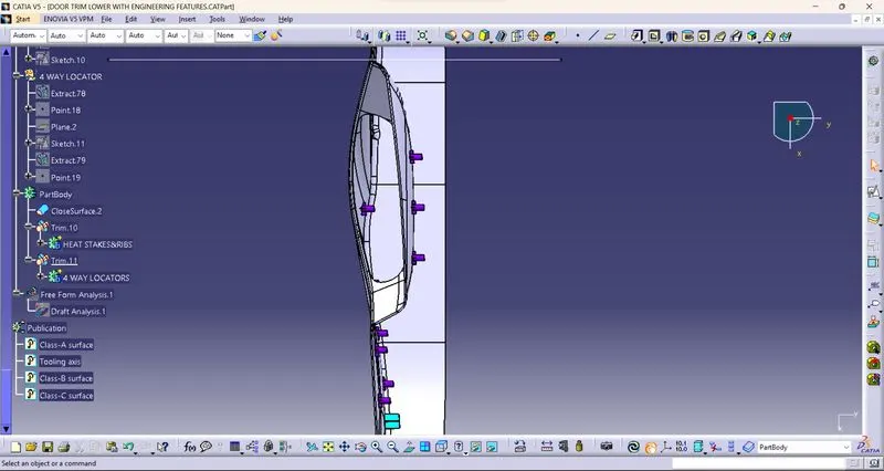
4WAY LOCATORS:
Thsi locator are use to control the degree of freedom A round locating pin located concentrically in a hole is a common application of a 4-way pin, and helps to further secure the piece. 4-WAY LOCATORS: 4-way mean you prevent movement at 2 axes (+X, -X, +Y and -Y) on the plane.
- Extract the surface and create a point as middle than select a plane as parallel through point than take a positone sketch create a lines of 25mm in horizontal and vertical axis and constrained them .
- use thick command to thicken the lines as 1mm as neutral fiber.
- Give a draft to all faces as 0.5 degrees neutral axis as plane pulling direction is tooling axis .
- Use Chamfer to edges of a locator as 1mm and 45degrees.
- Select the faces and eddges of a locator and fillet them .
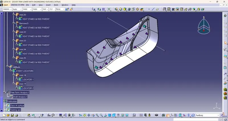
- Copy the locator body and define in part body paste as special use translate command to translate the duplicate locator in the desiresd location .
- Add this two locators in one body and union trim with main part body.
- Final draft analysi was done with 0.48 degree it was satisfied
Publications:
Class-A,Class-B,Class-C and Tooling Axis publications are in the Publication part body.
Note:
I was using a software of 2011 version. so some graphic properties not visible and showing like a errors .please consider my request thank you.
CLASS-A:
SOLID SURFACE:
DIFFERENT VIEWS:
NOTE: