Week 9 - Project 1 - Door Trim Lower with Engineering Features
Create the Door Trim Lower Plastic component through the given Class-A surface. To begin with, the tooling axis for the given Class-A Surface should be created meeting the requirements of the draft angle and at the end perform the Draft analysis on the model.
Create the Heat Stakes and the locators considering the design rules
CLASS A SURFACE
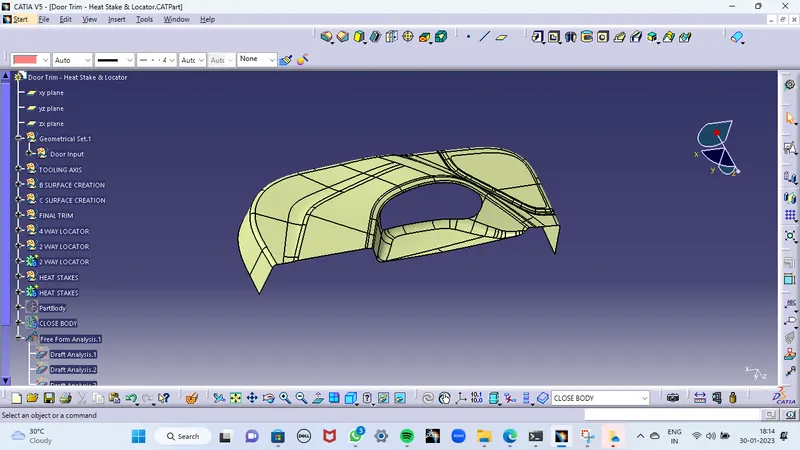
CLASS B SURFACE
- The first and foremost thing is to offset the CLASS-A surface for 2.5mm-3mm.
- Here I found some patches. This happened because of improper offset of filleted area.
- Then I work on the patches which are over the offset surface
- Now I get a surface like below
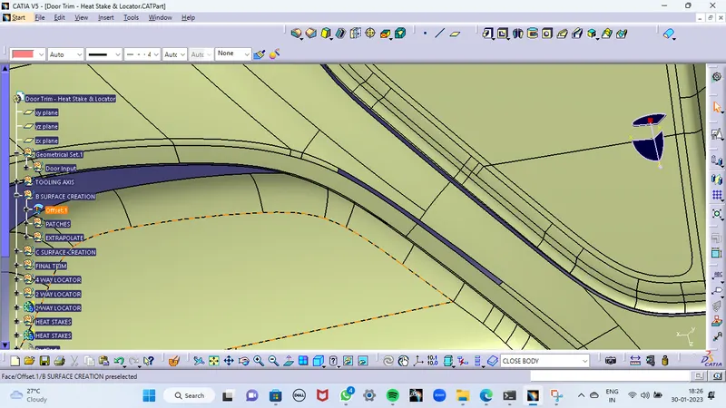
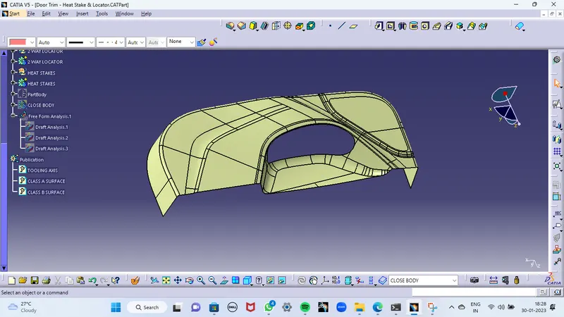
AFTER GETTING THIS SURFACE, EXTRAPOLATE IT TO GET A SURFACE LIKE BELOW
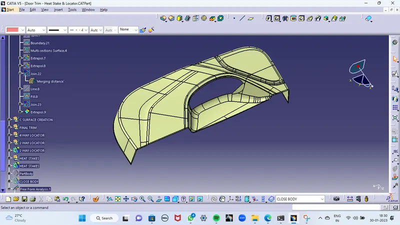
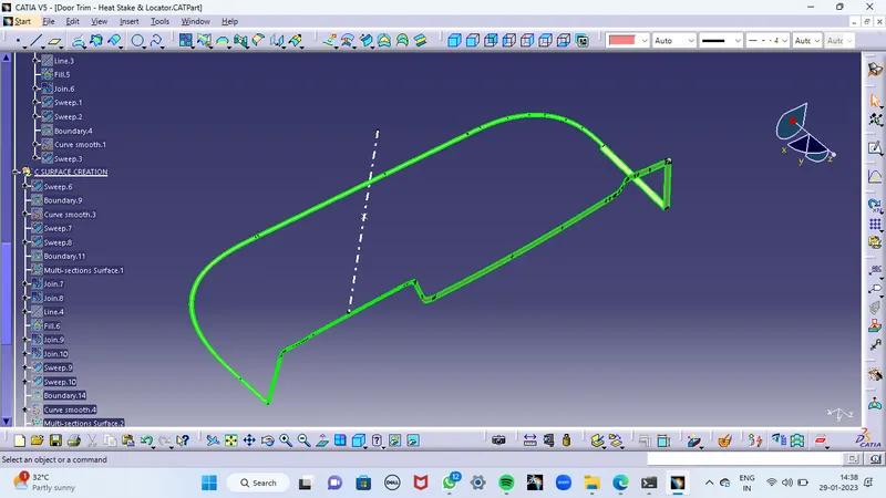
CLASS C SURFACE
- Sweep the class A surface according to the nature of the surface
- Join the class-c surface to the class-A surface together
- Now I got a surface like below
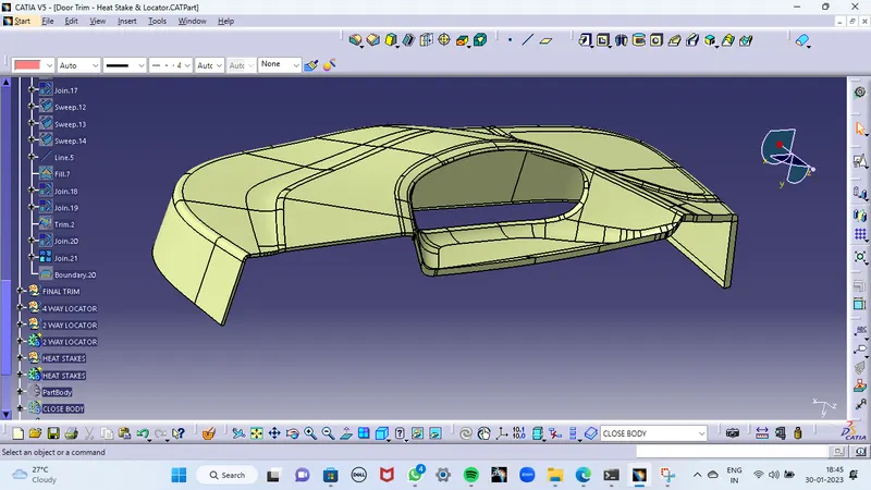
AFTER COMPLETING ALL THE OPERATIONS WHICH ARE MENTIONED ABOVE, UNHIDE THE EXTRAPOLATED CLASS-B SURFACE AND CLASS-C SURFACE TOGETHER. THEN I GOT A SURFACE LIKE BELOW
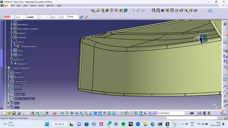
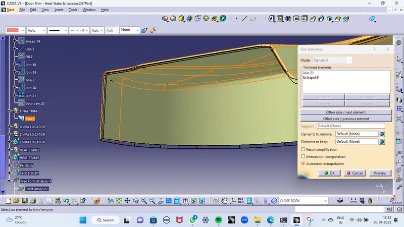
TRIM THEM TOGETHER TO GET A COMPLETED CLOSED SURFACE
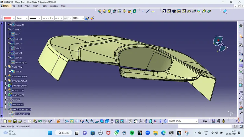
4 WAY LOCATOR
- CREATE A POINT ON THE B-SIDE WHEREVER IT NEED
- CREATE A PLANE PARALLEL TO THAT POINT
- CREATE A SKETCH OF THE 4 WAY LOCATOR
- INSERT A BODY AND PAD IT FOR THE REQUIRED LENGTH
- MAKE SURE THE PAD WILL CROSS THE CLASS-A SURFACE
- GIVE A DRAFT FOR ALL THE FACES FOR 0.5deg
- GIVE A FILLET VALUE TO GET A REQUIRED PROFILE
- NOW MAKE A UNION TRIM WITH A MAIN BODY
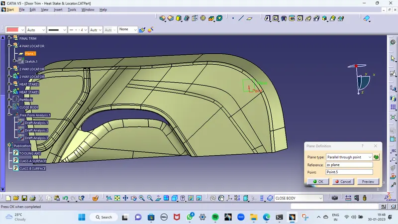
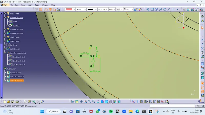
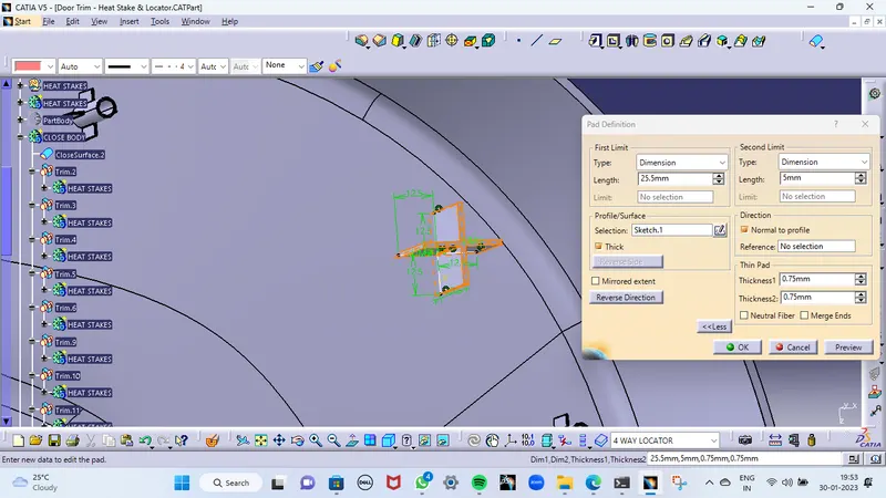
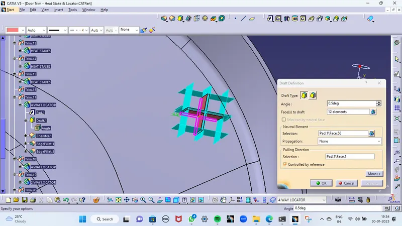
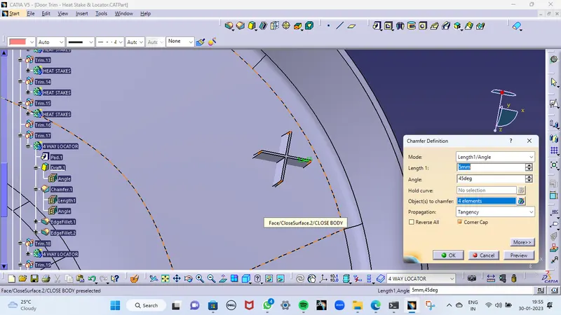
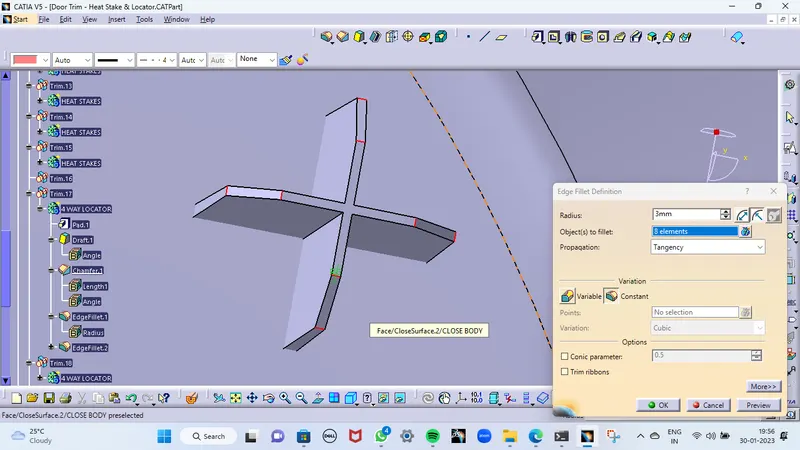
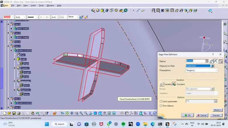
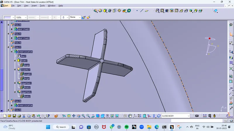
FINALLY, TRANSLATE IT WHEREVER IT NEED
2 WAY LOCATOR
- CREATE A POINT ON THE B-SIDE WHEREVER I NEED
- CREATE A PLANE PARALLEL TO THAT POINT
- CREATE A SKETCH OF THE 4 WAY LOCATOR
- INSERT A BODY AND PAD IT FOR THE REQUIRED LENGTH
- MAKE SURE THE PAD WILL CROSS THE CLASS-A SURFACE
- GIVE A DRAFT FOR ALL THE FACES FOR 0.5deg
- GIVE A FILLET VALUE TO GET A REQUIRED PROFILE
- NOW MAKE A UNION TRIM WITH A MAIN BODY
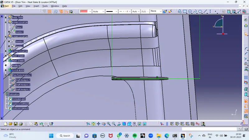
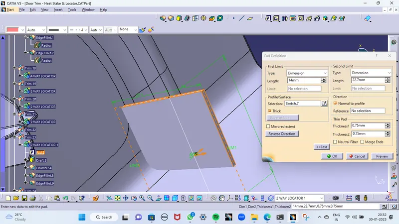
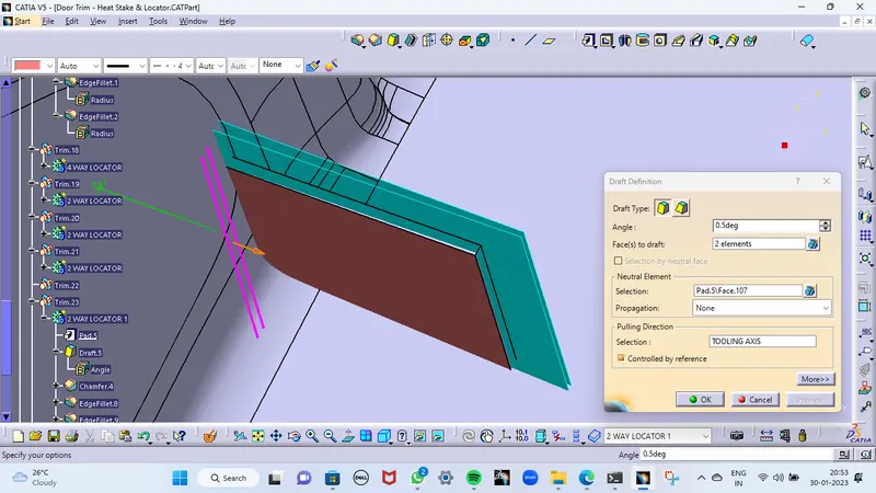
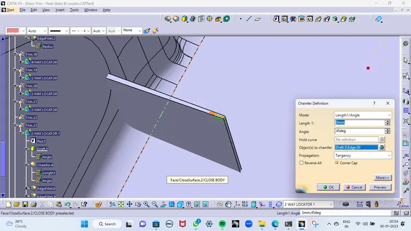
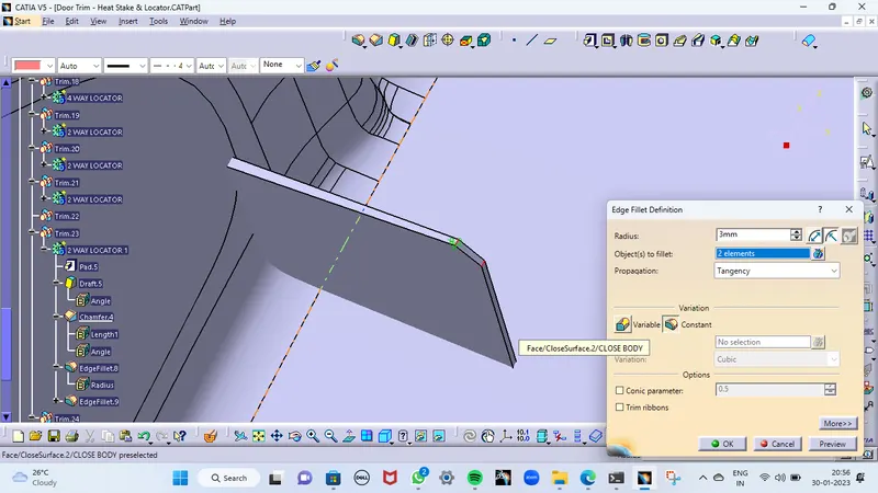
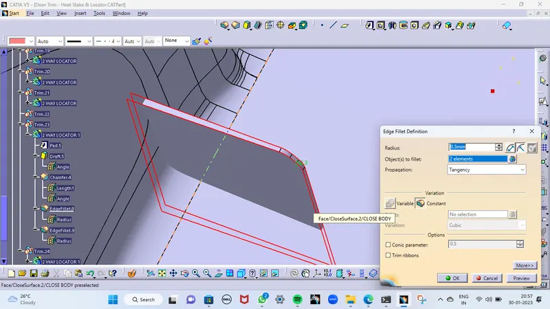
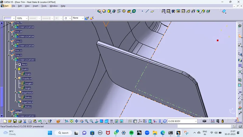
FINALLY, TRANSLATE IT WHEREVER IT NEED
SIMILARLY, DO ALL THE ABOVE OPERATIONS FOR CREATING HEAT STAKES TO GET A OUTPUT LIKE BELOW
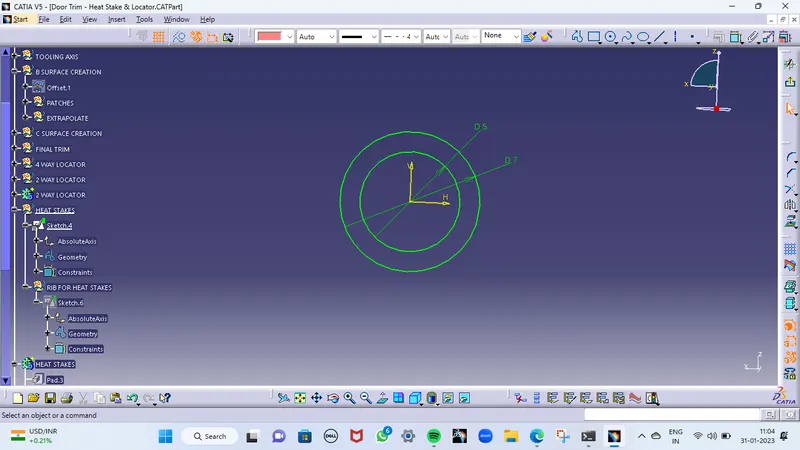
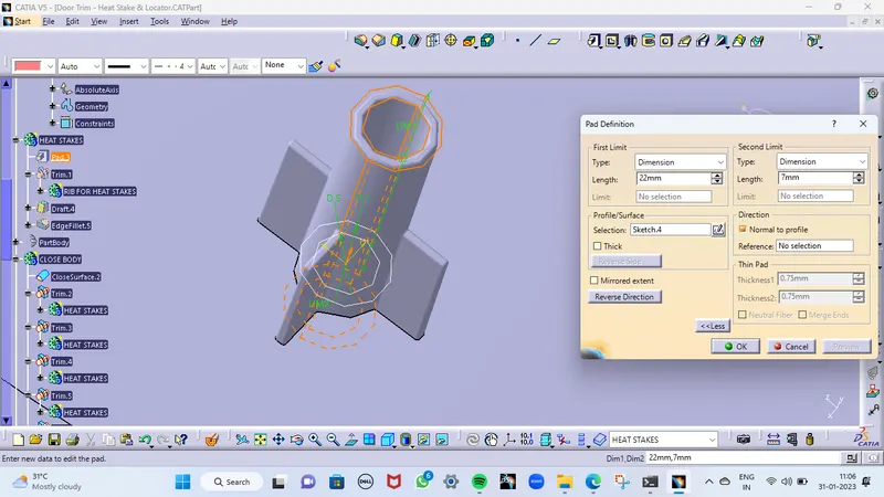
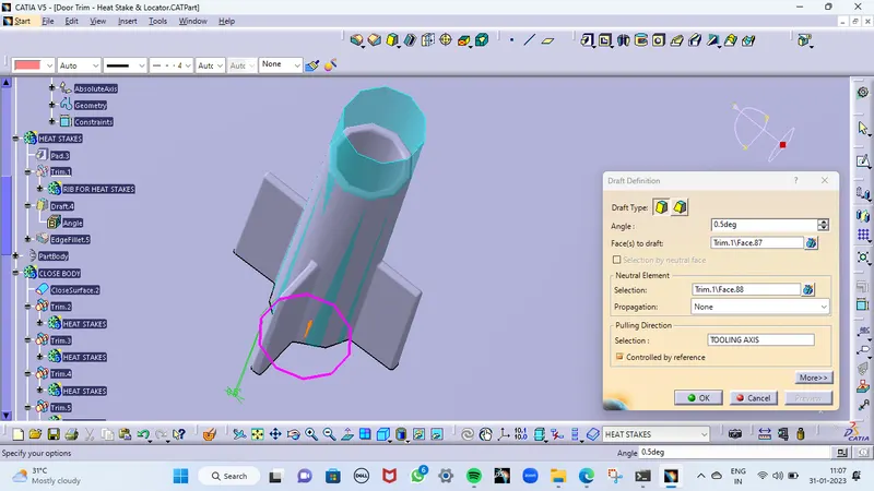
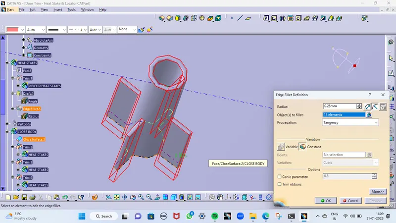
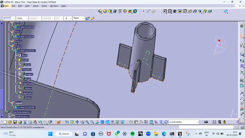
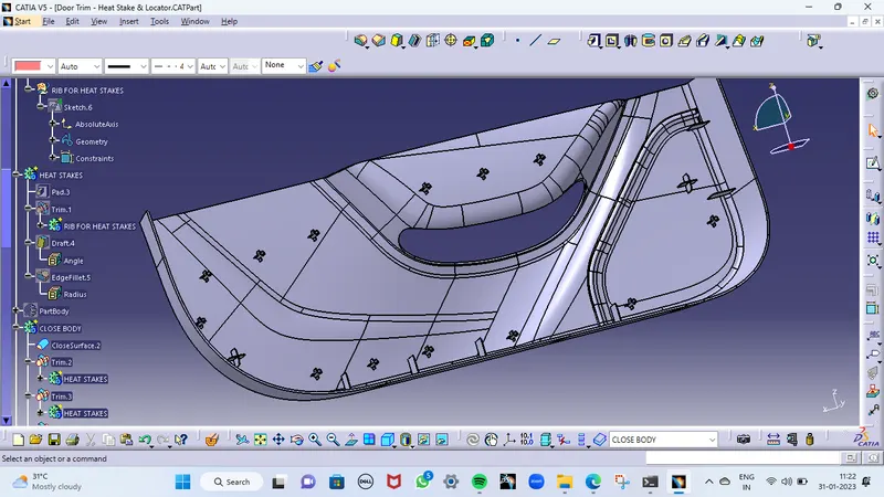
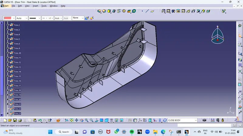
NOW I HAVE A DIFFERENT SOLID BODY ASSOCIATED WITH THE MAIN BODY. JOIN ALL TOGETHER TO GET A SINGLE BODY BY PERFORMING UNION TRIM. AFTER COMPLETING ALL THE OPERATIONS WHICH ARE MENTIONED ABOVE. I GOT A BODY LIKE BELOW
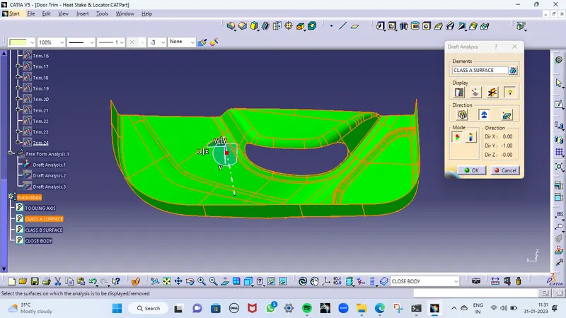
DRAFT ANALYSIS
DRAFT ANALYSIS FOR THE CLASS-A SURFACE
DRAFT ANALYSIS FOR THE FINAL COMPONENT
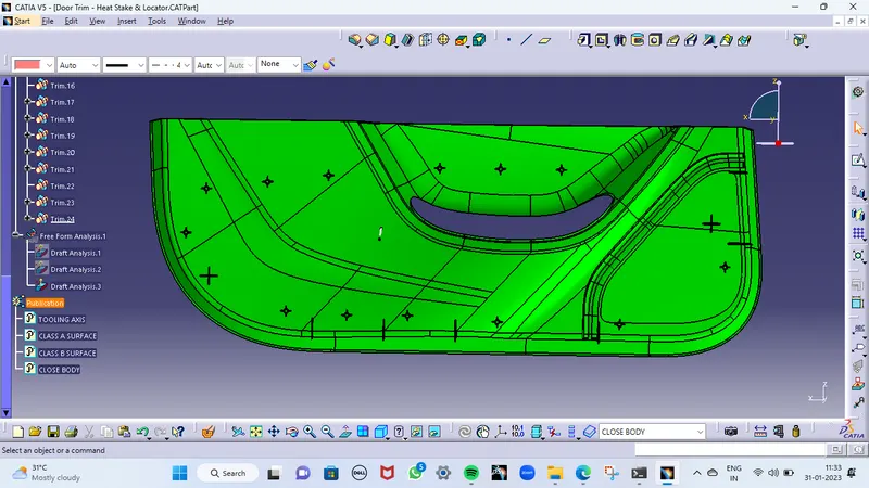
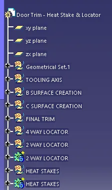
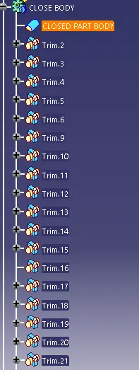
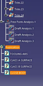
TREE STRUCTURE
DIFFERENT VIEWS
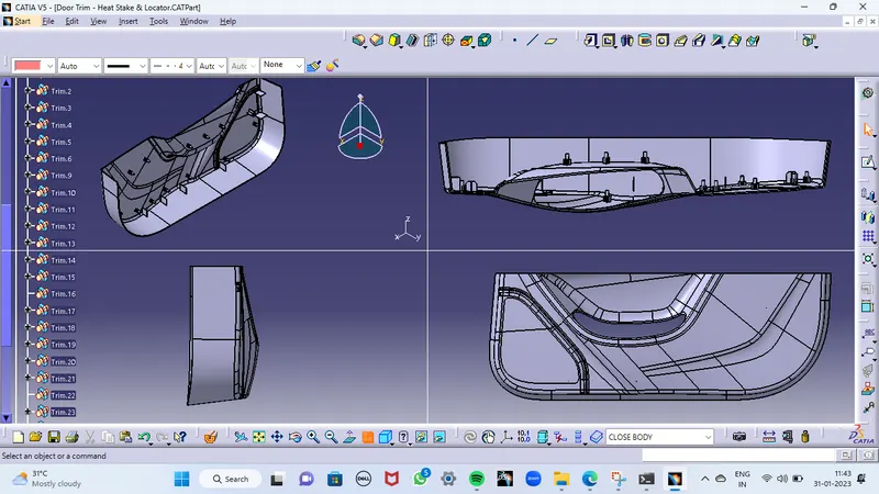
ISOMETRIC VIEW
CONCLUSION
The final plastic component from the class A surface is created and also the engineering features are also develo[ped on that body. Then the draft analysis was also performed on both class A and the final product.
*****THANK YOU*****