Week 9 - Project 1 - Door Trim Lower with Engineering Features
Aim : To create a model of door trim lower design from given class A surface and add engineering features like heat stakes and locators and to do draft analysis.
Objective :
- To create class B and class C surface .
- To do draft analysis .
- To add engineering features and perform draft analysis of it .
- To make report of it .
Introduction :
Class A surface :
- It is asthetic part of car created through scaning of clay model .
- This is the input CAD model for part design .
Class B surface :
- It is surface for engineering advancement .
- It is created at the thickness value of component toward inside .
Class C surface :
- class C surface is created by joining class A and class B surface .
Methodology :
- checking continuity of surface.
- Tooling axis.
- Draft analysis.
- Class B surface.
- Class C surface .
- Making solid body .
- Adding engineering features like heat stakes and locators.
- Draft analysis of final product .
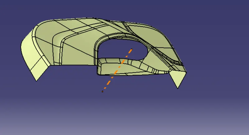
Tooling axis :
- The direction in which the mould open and close is called tooling direction.
- Extract the base and create the point at the center .
- from that point creat line which is tooling axis.
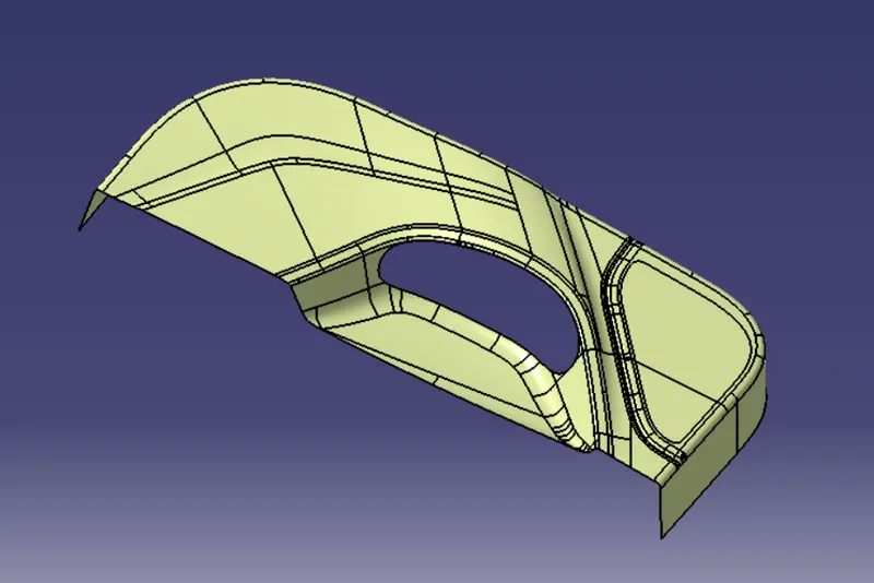
Given class A surface :
Tooling axis :
B surface creation :
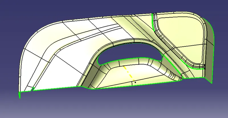
- offseting class A surface inward by 2.5 mm which is the thickness .
- By ofsetting class A surface , some patches are created .
- repairing it through join , extrude ,sweep , multiple extract , trim command.
Final Class B surface :
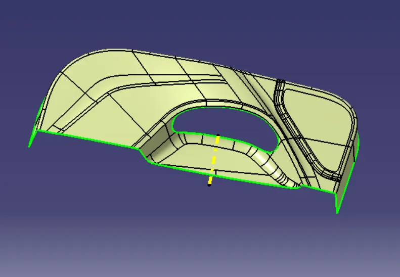
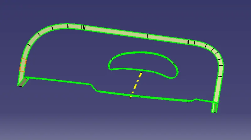
Creation of C surface :
- Boundary of class A surface is extracted and middle portion is also extracted .
- Sweep command is used to create C surface at 90 degree of class surface .
- class C and class B are trimed and join with class A surface .
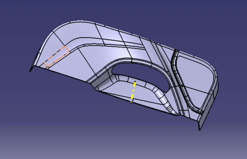
Creating solid body :
Finally solid is body is created by using close surface command .
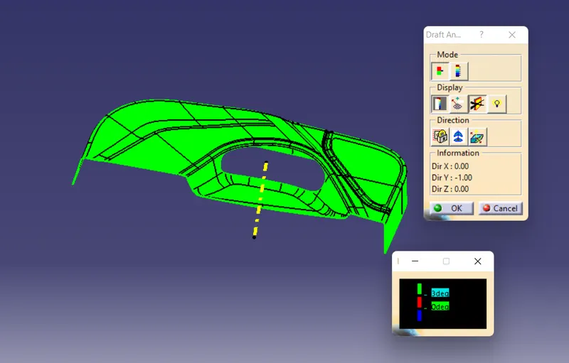
Draft analysis :
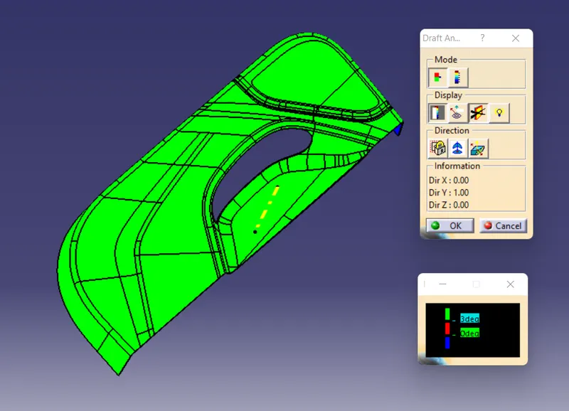
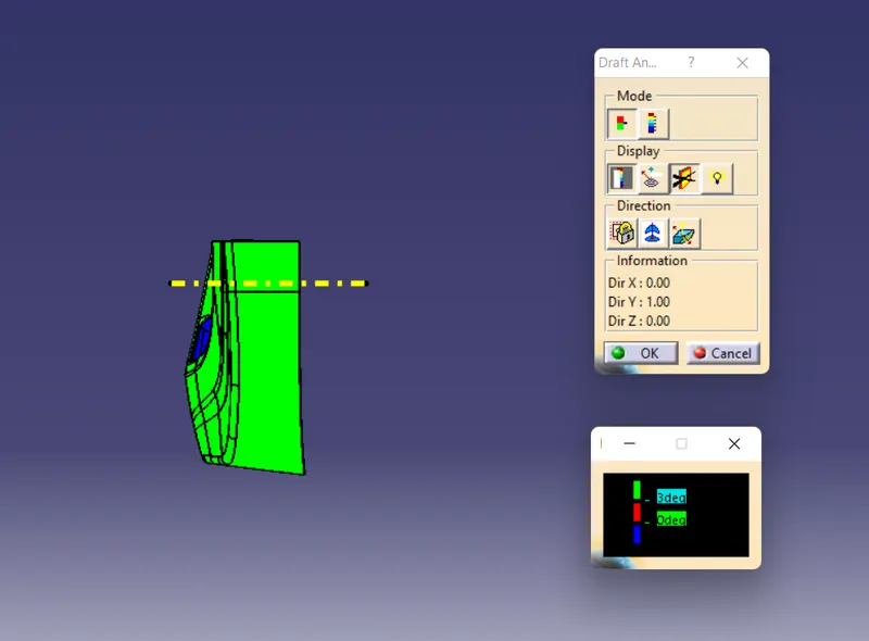
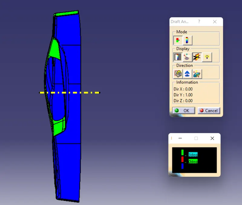
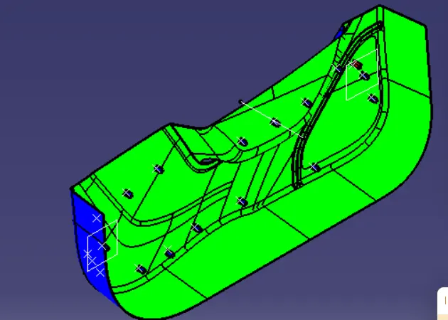
- First the material mode is selected in custumize view swction.
- Now click on the compass tab and align it with tooling axis .
- Now click on the lock .
- click on the surface .
- Surface colour shows green , which mean that the it has more than 3 degree angle , which is good for manufacturing .
Class A surface :
Final body :
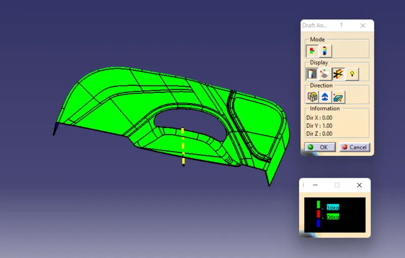
Different views are as :
Isometric view :
Front view :
Side view :
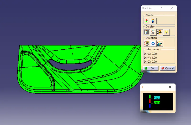
Top view :
Adding engineering features :
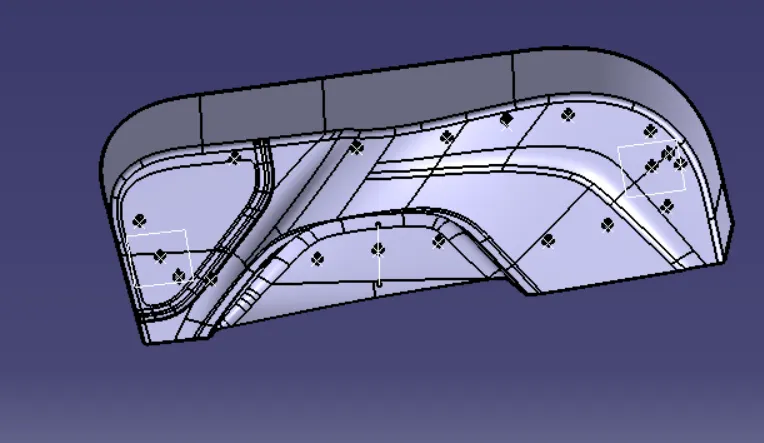
locators and heat stakes :
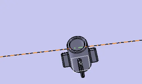
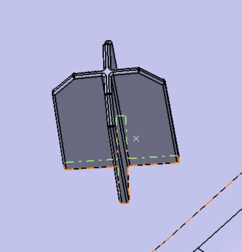
- The heat stakes is used to join components.
- will enter the mating component and using a heat staking machine these heat stakes are melted and cooled.
- When it gets cooled down both part will mate with each other.
- Thus all degrees of freedom are arrested .
- The ribs for heat stake are created by following the rib design rules.
- Hence, the ribs are created for the screw HEAT STAKES.
- The door applique is fixed on to the door surface with the help of locators and heat stakes.
- Every component in space has 12 degrees of freedom.
- So these locators and heat stakes restrict all these degrees of freedom.
- Locators are 4-way locators and 2 ways locators .
- The locators will follow the rib design guidelines and will be given a minimum draft of 0.5 degrees and a minimum fillet of 0.2mm and an entry chamfer of 3mm.
- This entry chamfer is given so that the locators can mate with the other part easily.
Draft analysis of body with heat stakes and locators :

Different views:
Isometric:
front :
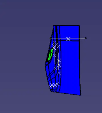
right :
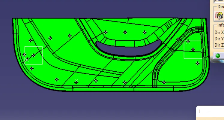
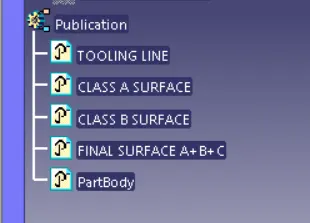
Tree structure :
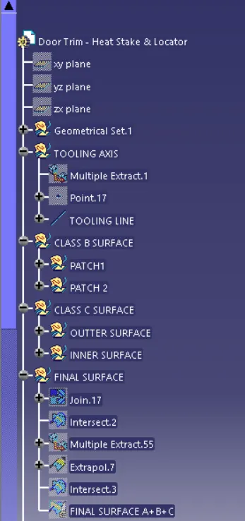
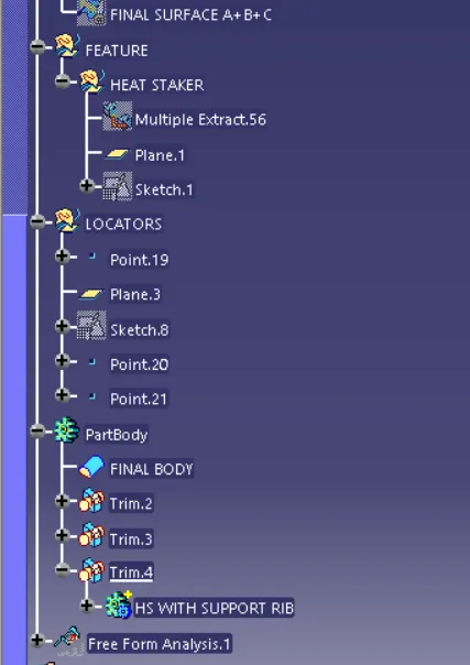
Publication :
Conclusion:
- Created class B surface and class C surface for door trim .
- crestred engineering features .
- Perform draft analysis .