Week 9 - Project 1 - Door Trim Lower with Engineering Features
Design and Analysis on Door Trim Lower with Engineering Features
Input:
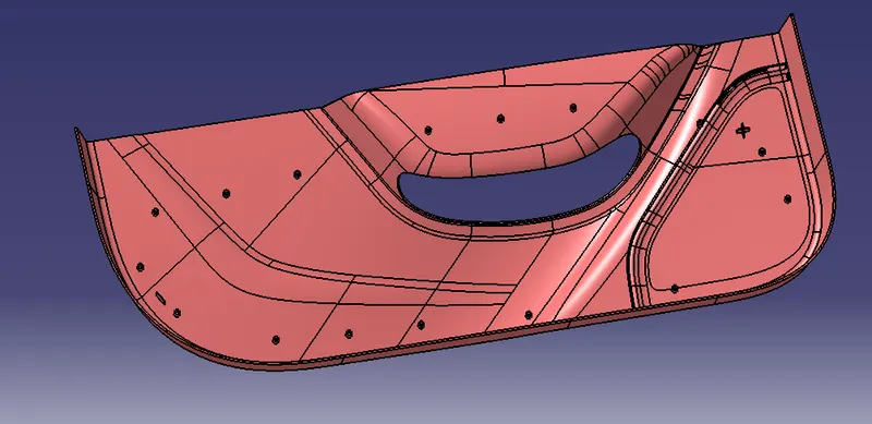
Class A surface: It is one of the most important input in automobile industry specially in plastic design and is also one of the stages of design life cycle usually class A surfaces are created in Autodesk Alias for sketching concept modelling and visualization and then New product development in cad software is carried out. Class A is an aesthetic surface,
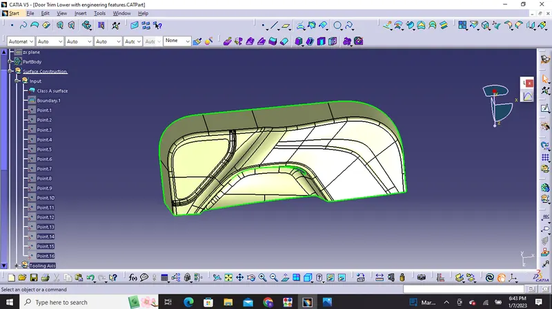
we will check the class A surface by putting boundary command on it and check for any irregularities so as to ensure that class A surface given is of good quality .
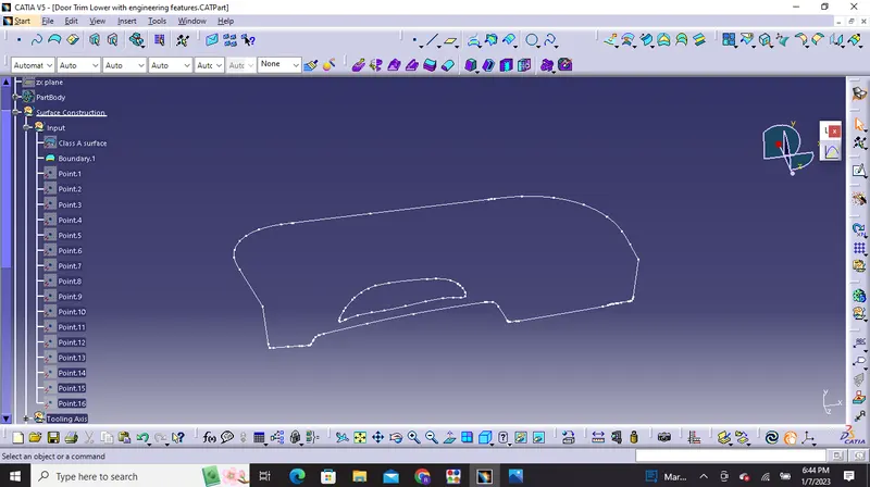
Class B Surface: B surface is the surface which gives us thickness from the class A surface, Class B is the engineering surface as all the engineering features like ribs ,boss etc are made on this surface.
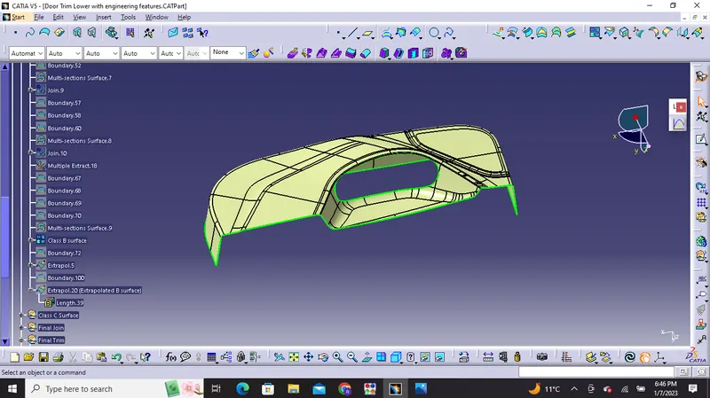
Class C Surface: C surface is the surface which connects A and B along the tooling direction and is called Class C surface.
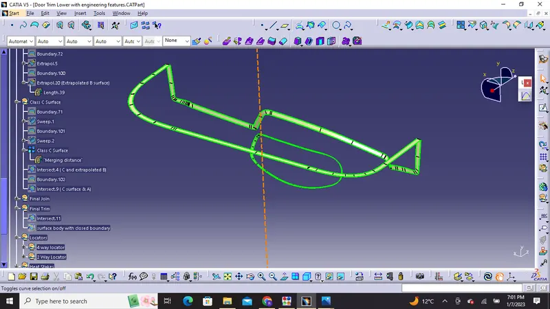
Tooling Axis
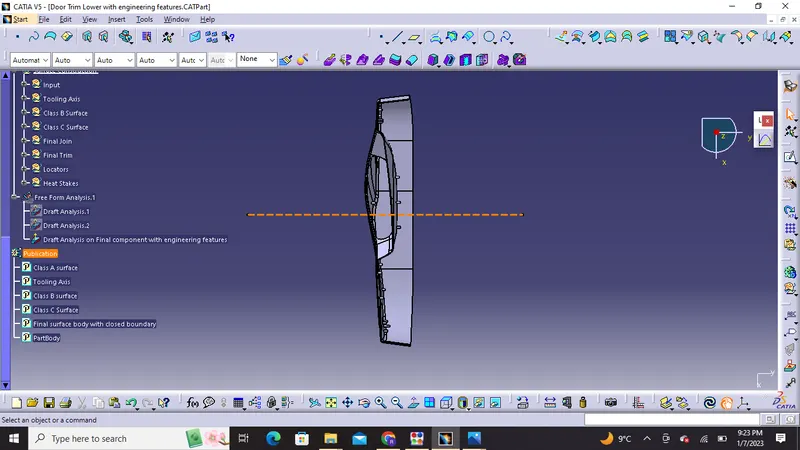
we can extract a surface from class A and create a point in the middle of that surface by using point command and create a line normal to that surface at that point through the y axis and we will perform draft analysis to check whether the created tooling axis is in the correct position or not , If in the draft analysis both the surface sides are in green color our position is correct.
or we can also follow bisection method through intersection.We can make tooling axis by center point on the model and using intersection we can create bisecting lines and bisecting line will bisect the two lines if they are perpendicular and will show some error if they are parallel this will decide that whether the surface is toolable or not and then perform draft analysis on it as we performed on previous projects.
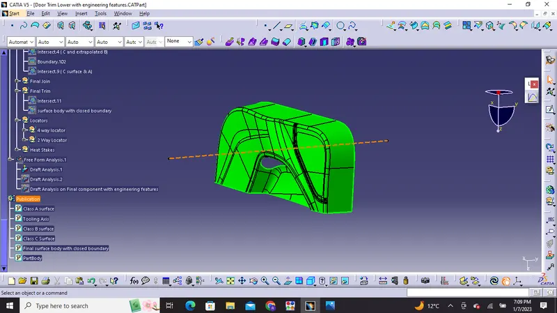
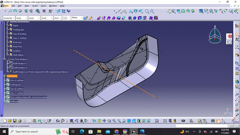
But for Tooling axis creation in complex and large parts like door trim ,bumpers,etc we can also draw tooling axis in the centre of gravity point using inertia method as The centre of gravity is a point in an object where the distribution of weight is equal in all directions and this point will be suitable for the direction of extraction of component very easily. Then we can view the component in all directions and for this bumper x direction will be best for creation of tooling axis using the centre of gravity point
Steps for inertia method are as follows:
1) We will click on measure inertia button which is beside measure item .
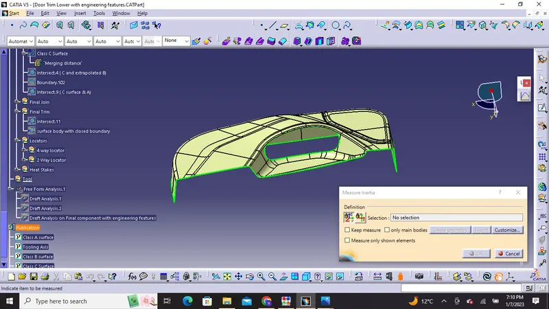
2) After selecting Class A surface we will next click on create geometry
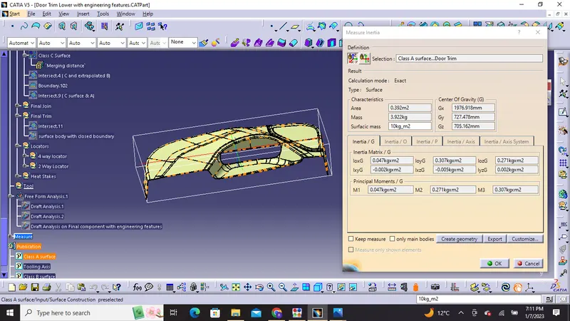
3) Furthermore we will click on non associative geometry and select centre of gravity and press ok
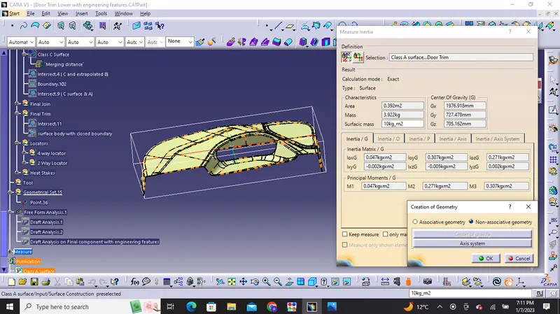
4) The inertia point will be created.We will select a line and select point and direction in which inertia point and Y direction is choosed for final creation of tooling axis
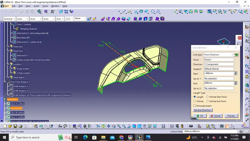
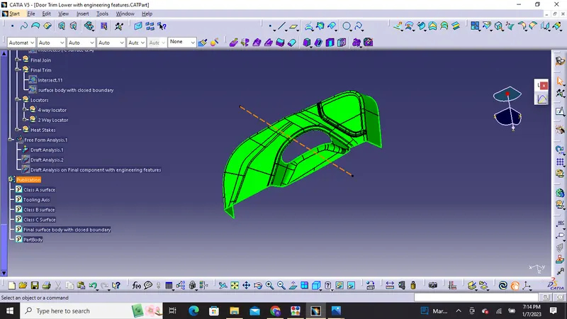
Final Tooling Axis
Draft Analysis:
Draft is the angle in which the part is tapered to allow it to release from the mold properly and as the part is cooled it has a tendency to shrink towards the core side of the mold due to this we need to add draft angles.Nominal draft angles is usually around 3 degrees and more than 3 degrees can also be manufactured like 5 degrees but it will unecessarily increase the costing of manufacturing and final product.
Procedure used for draft analysis in Catia cad software:
1) In display frame first we need to change it to material mode
2) Click on insert then analysis and select feature draft analysis
3) Then we will click on compass and and align it with tooling direction.
4) Then we will click on the lock symbol and then click on the surface of the part the colour will change
5) Different color codes are identified and there we can apply draft angle which will reflect us minimum draft angle in green color.
6) We can also have running point analysis on different regions of the part body for permissible draft angle.
Draft Analysis on Class A surface
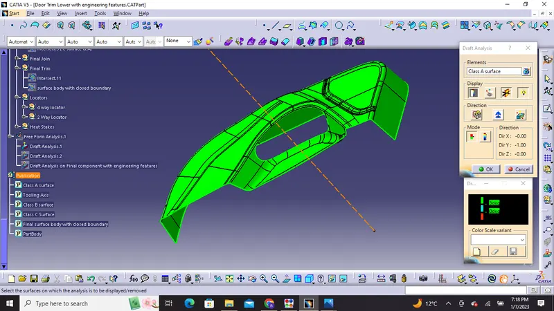
Minimum Draft Angle 3 Degree
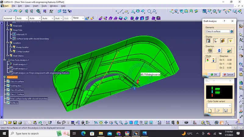
Running point analysis on inward side
Locators & Heat stakes
Significance of 3-2-1 Principle: The 3-2-1 principle of a location six point location principle is used to constrain the movement of workpiece along the three axes XX,YY, and ZZ. Any part which has to be fixed during welding or during machining process has to be fixed. Every object is having 12 degrees of freedom.
By Degree of freedom we mean the capability of a body to move in twelve different directions six rotational and six axial. Engineering features like locators are used to follow this principle.
Locators are also divided into 4 way locators and 2 way locators . A 4 way locator mean we prevent movement at 2 axis (+X, -X, +y and -y) on the plane,generally we have cylindrical pin on the fixture and circular hole at workpiece part. On the other hand 2 way locator means we can prevent movement at 1 axis on the plane nad we generally have the cylindrical pin on the fixture and slot hole at work piece part.
Generally we use one 4 way locator and one 2 way locator at the same time.
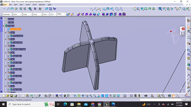
'4 way locator '
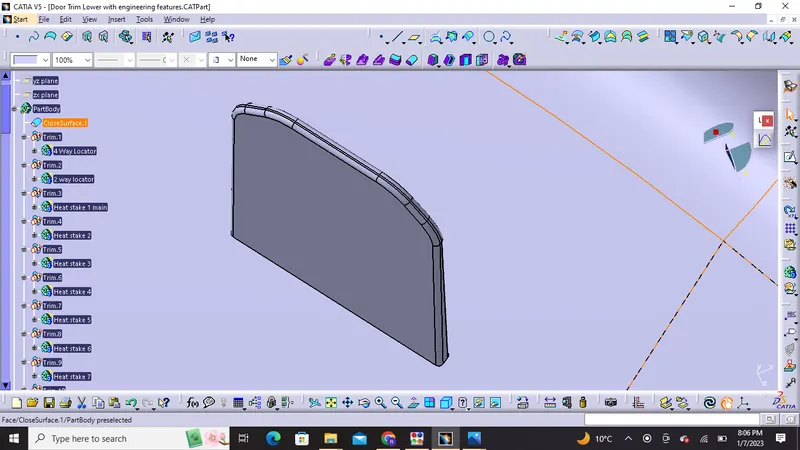
'2 way Locator'
Design procedure for 4 way locators
1) We have to create a positioned sketch.
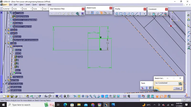
2) We have to pad it along the tooling axis
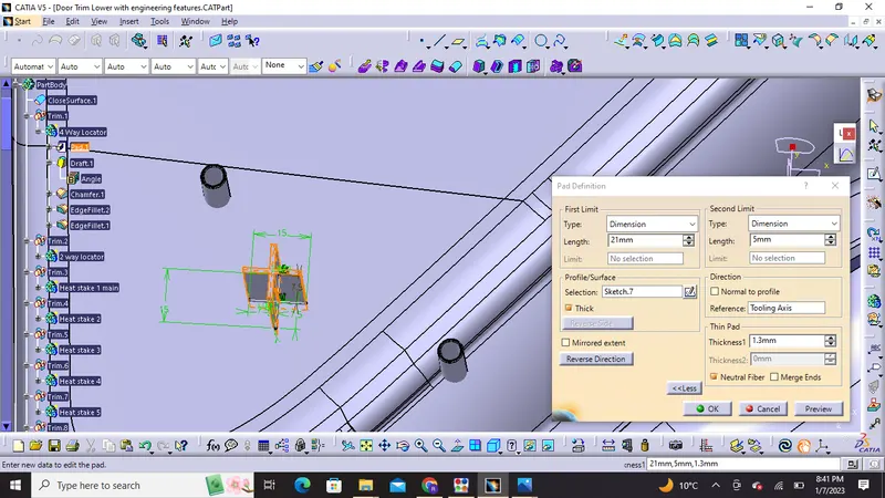
3) we have to apply Draft angle of 0.5 degrees in all the faces.
4) we have to apply a chamfer of 3*45 degrees on the to face for the penetration of the locators into the holes.
5) Edge fillets of 0.3 mm are given to all the edges.
Most important thing while giving draft is that we have to select it along the tooling axis.
Design procedure for 2 way locators :
1) We have to create a positioned sketch.
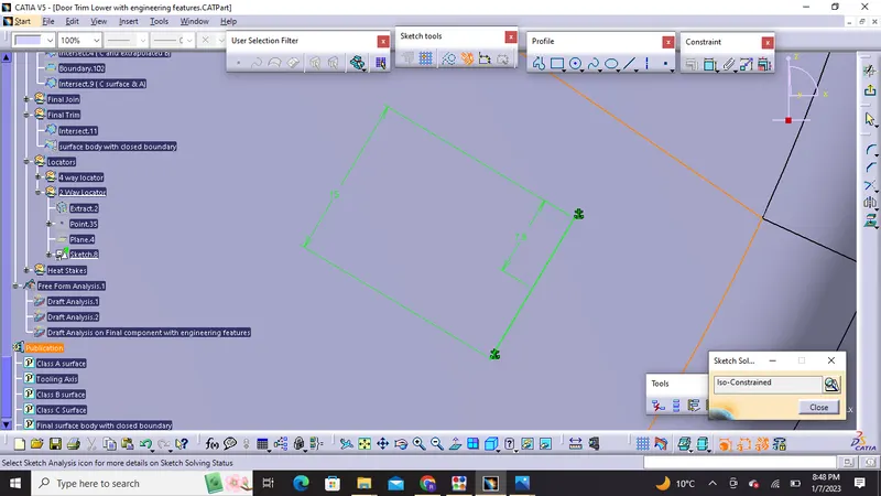
2) We have to pad it along the tooling axis
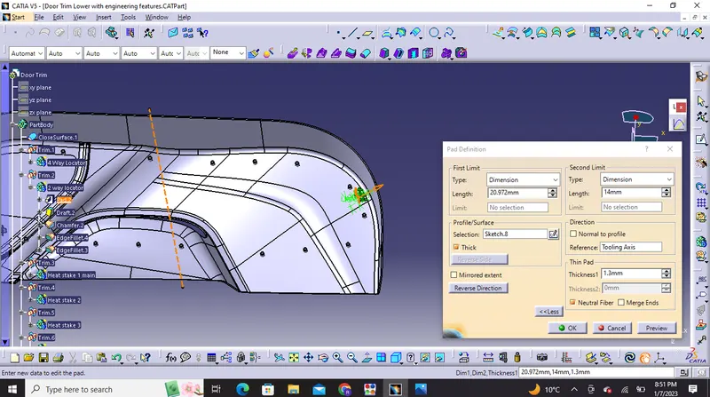
3) A draft of 0.5mm is given on the faces
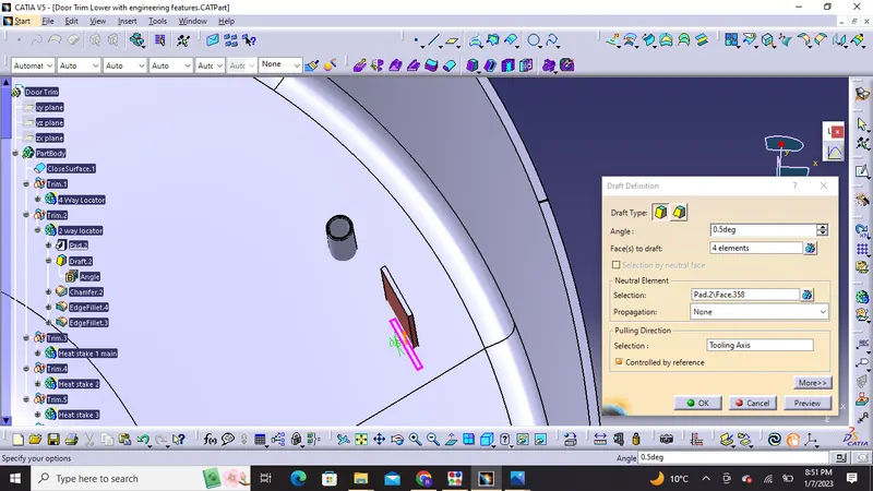
4) we have to apply a chamfer of 3*45 degrees on the to face
5) Edge fillets of 0.3 mm are given to all the edges.
Most important thing while giving draft is that we have to select it along the tooling axis.
Heat stakes: Heat staking technology is quite simple in concept. Whenever two or more components need to be attached to one another, and at least one is made of a thermoplastic, a combination of heat and pressure can be used to reform the plastic to the many shapes or profiles to retain or join the parts together. It is also called thermal staking which is an assembly method that uses controlled melting and reforming of a plastic stud or boss to capture or lock another plastic or metal component of an assembly in place.
The plastic stud protudes through a hole in the component to be locked in place. The heated thermal tip contacts the top of the stud which melts and fills the volume of the tip cavity to produce a head , locking of the component in place.
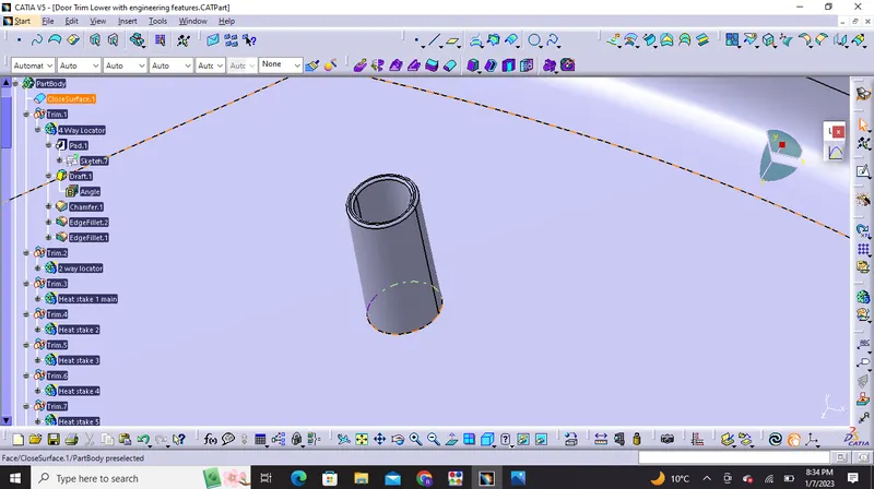
Design procedure for Heat Stakes :
1) We have to use positioned sketch
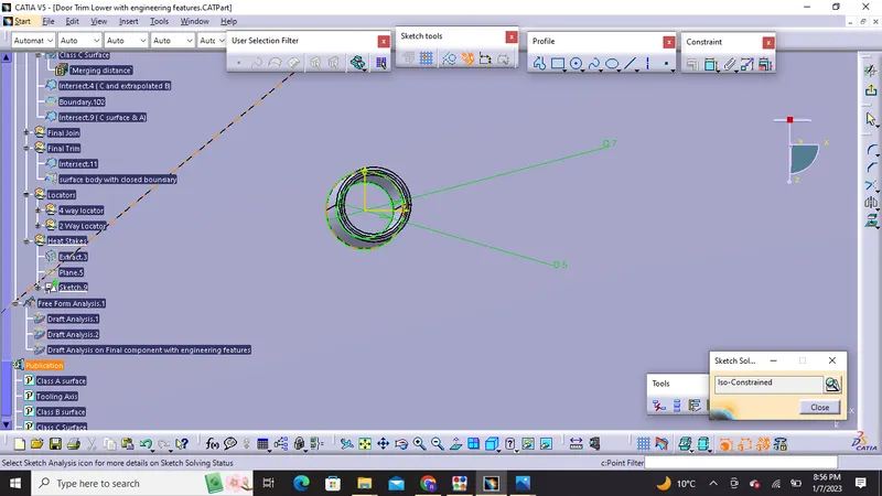
2) We have to pad it along the tooling axis but we have to make one thing for sure that the height of heat stakes should be lower than that of the 4 way and 2 way locators
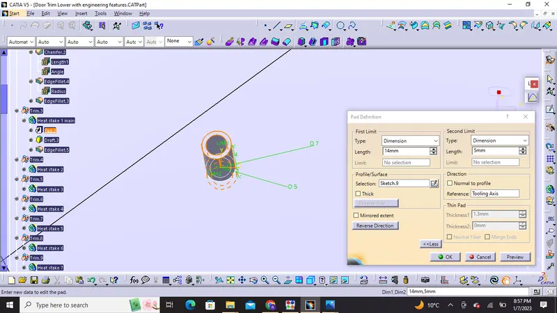
3) We have to provide a draft angle of 0.5 degrees on both walls of the heat stake.
4) The minimum gaps between each heat stakes should be of 50 mm .
Furthermore we can create one heat stake and then use translation by point to point method and create more number of heat stakes on the required part.
Draft Analysis on Final component with engineering features :
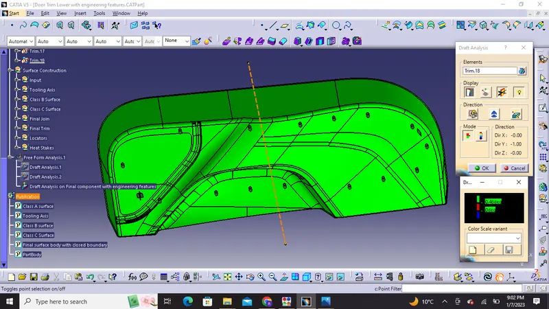
Draft angle of 0.48 degrees
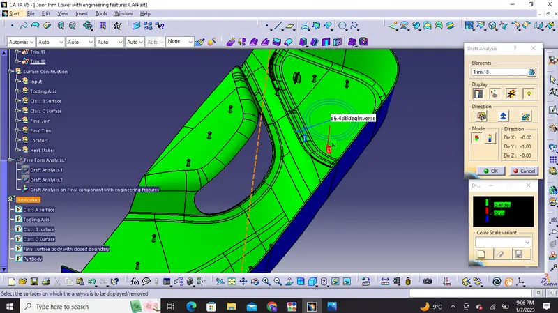
Running Point Analysis
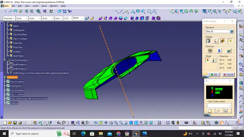
On inversing the draft direction the color changes on opposite side
Part Tree :
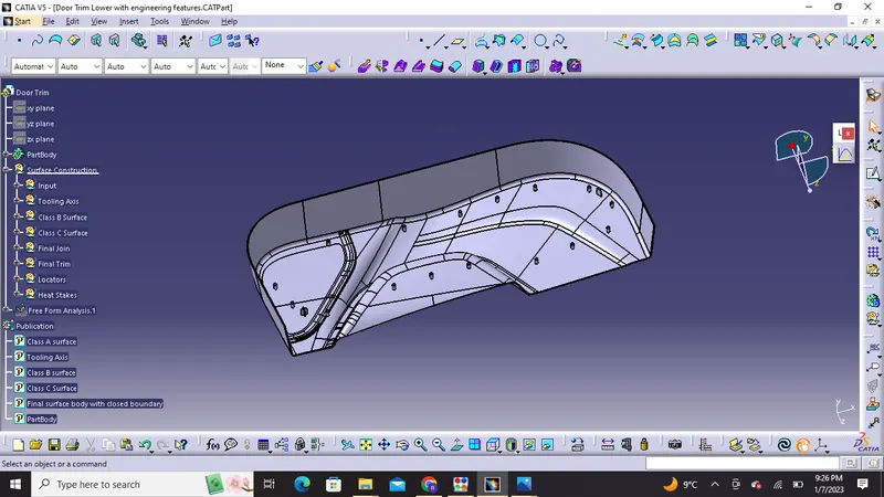
Different views of the solid body in various orientations :
1) Isometric View:
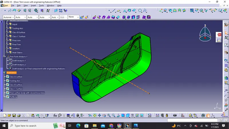
2)Front view
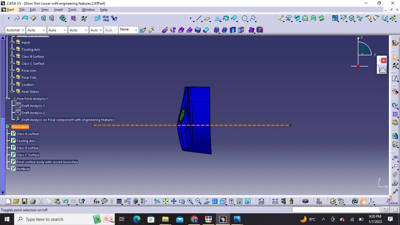
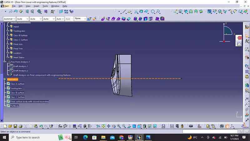
3) Side view
Left view
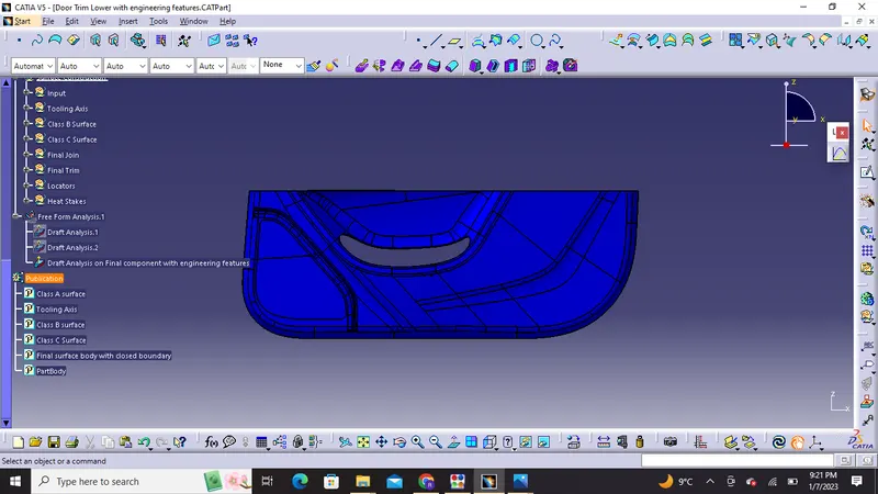
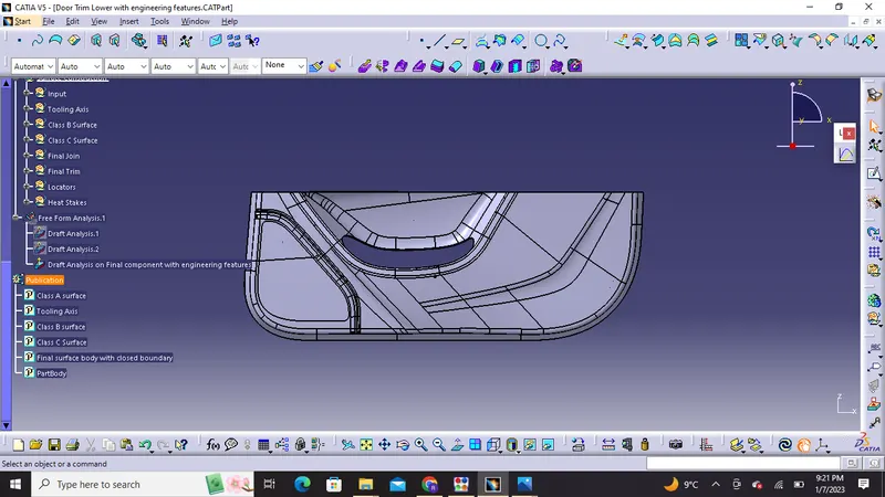
Right View
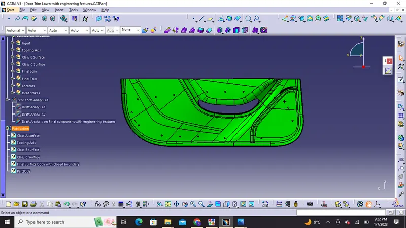
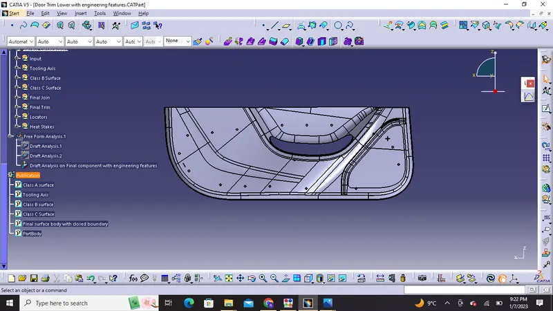
4) Top view
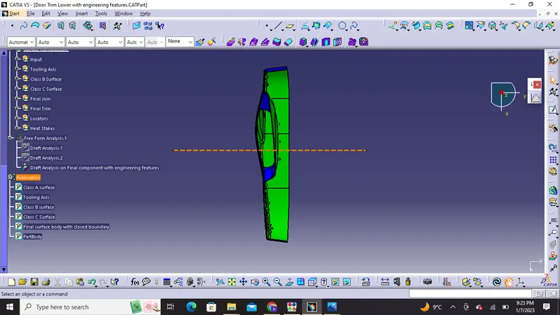
Output:
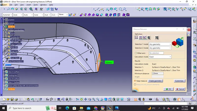
Thickness of component 2.5mm