Week 9 - Project 1 - Door Trim Lower with Engineering Features
Door Trim Lower with Engineering Features
Input:
class a surface
Tooling axis
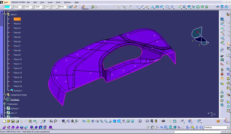
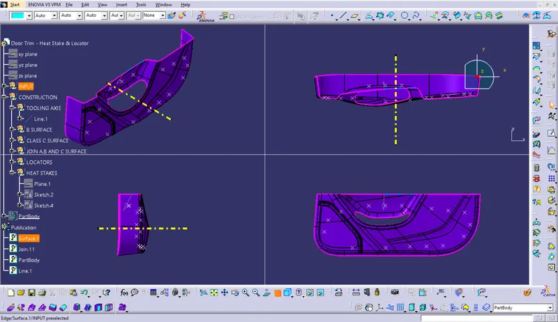
- For Creating the tooling axis, we create a straight line from the selected point on the surface in the Y direction.
Draft analysis for class a surface
-
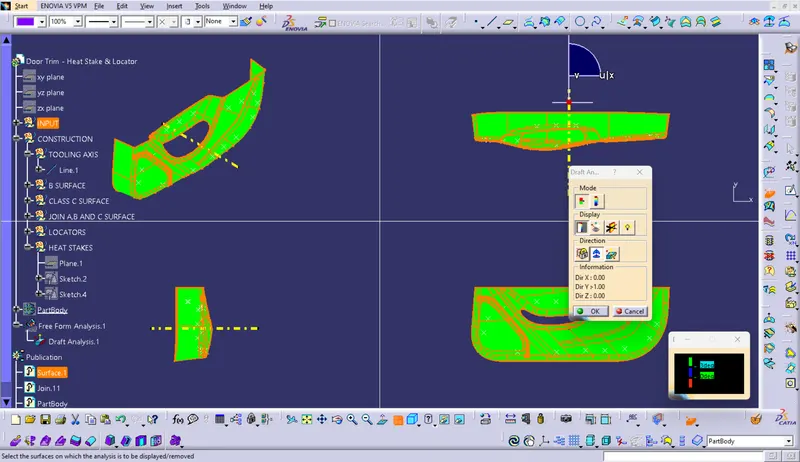
Checking the tooling axis by draft analysis.
-
The draft analysis is done to determine if the designed part is tool able or not. Here the tooling axis is 3°.
B surface
- The B surface is created by an offset value of 2.5 mm
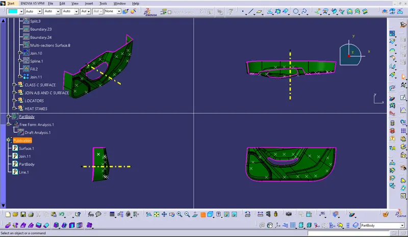
Class c surface
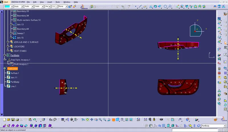
Part body
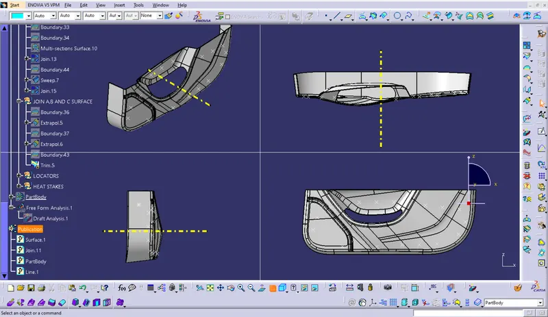
Locators:
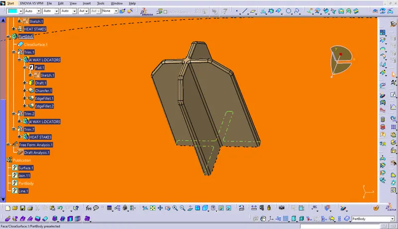
Sketch Plane is made in the tooling axis direction.
Height = 20 mm
Wall Thickness = 1.3 mm
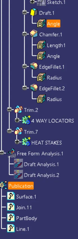
Draft Angle = 0.5°
Chamfer = 3 mm, 45°
Fillet 0.3 mm & 3 mm
Heat stakes
Sketch Plane is made in the tooling axis direction.
The length of heat stakes should be at least 5 mm lesser than locators, L = 15mm
Radius, ID = 5mm, OD = 7 mm
Draft Angle = 0.5°
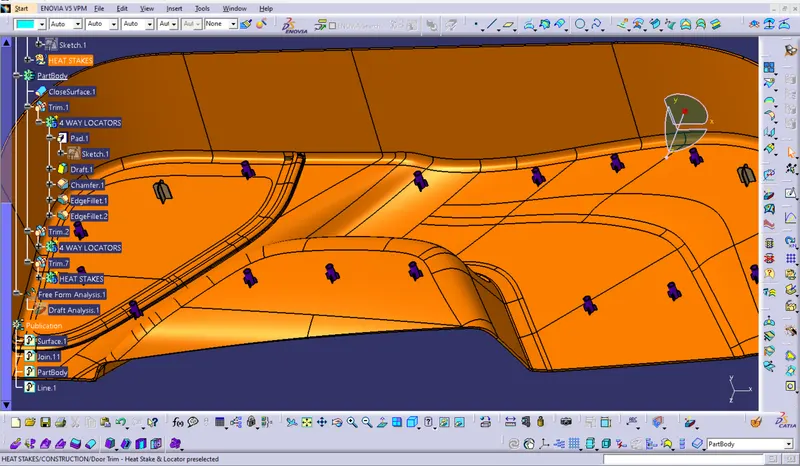
Final output:
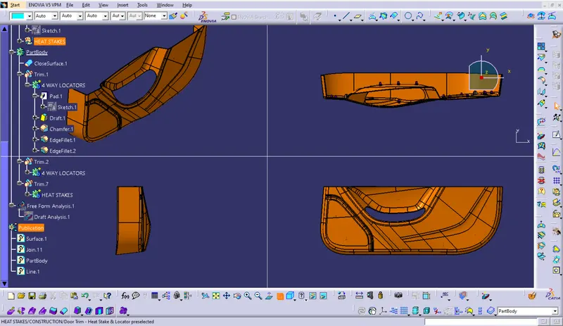
Final draft analysis:
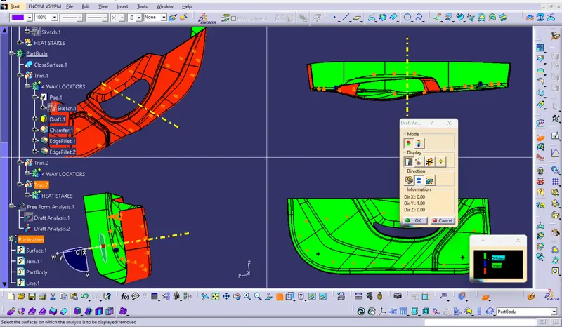
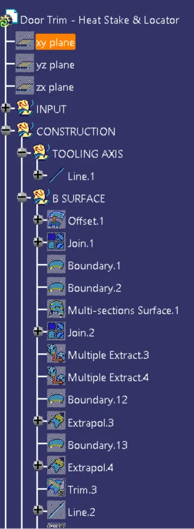
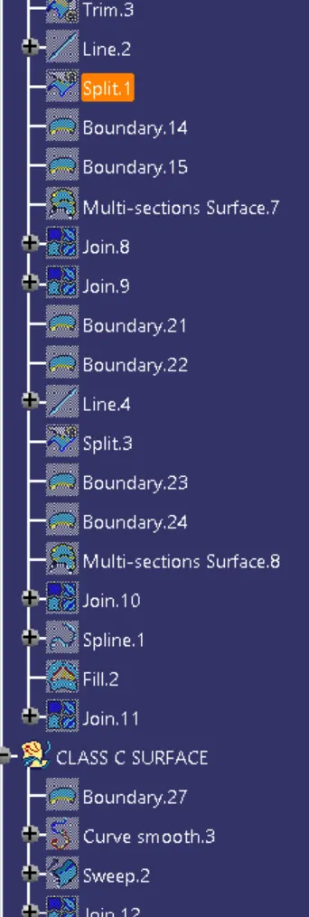
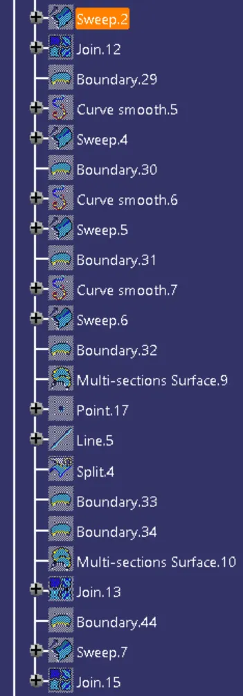
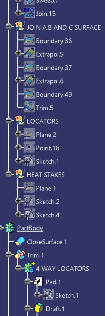
Tree structure