Week 9 - Project 1 - Door Trim Lower with Engineering Features
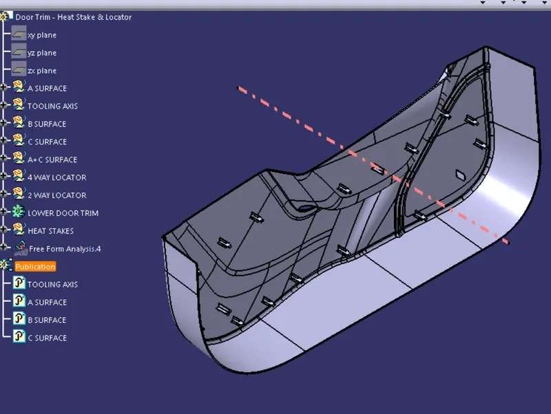
Week 9 heat stakes on door trim challenge
Isometric view
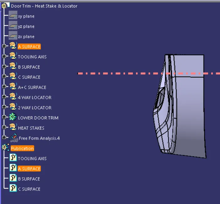
Front view
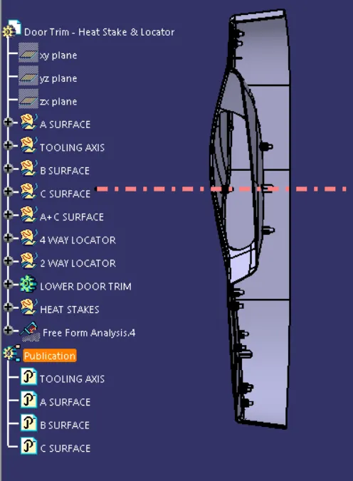
Top view
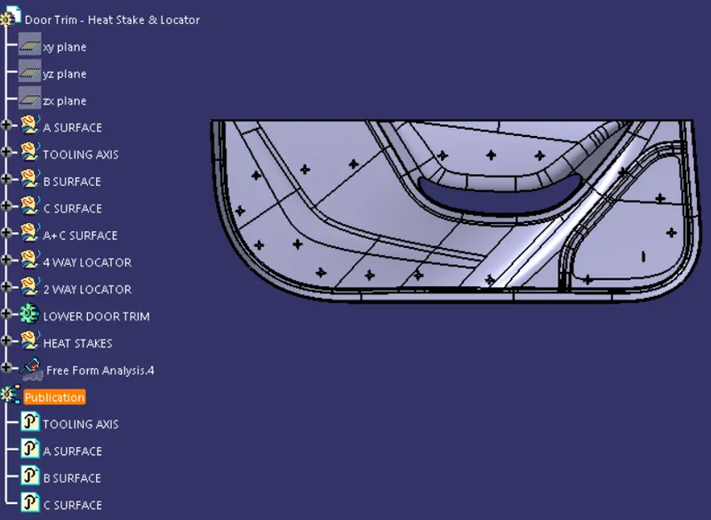
Right view
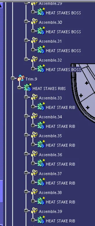
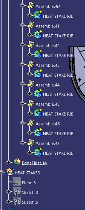
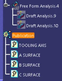
Model tree
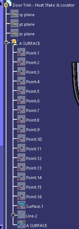
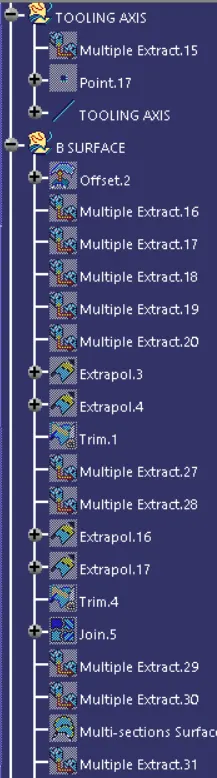
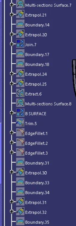
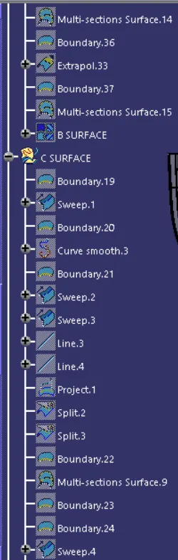
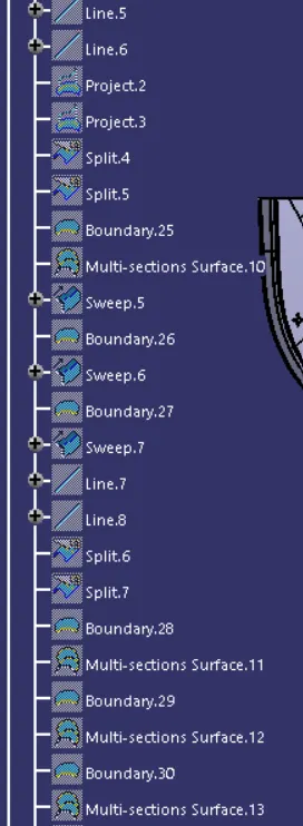
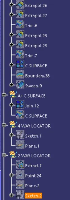
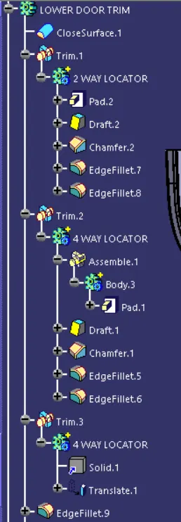
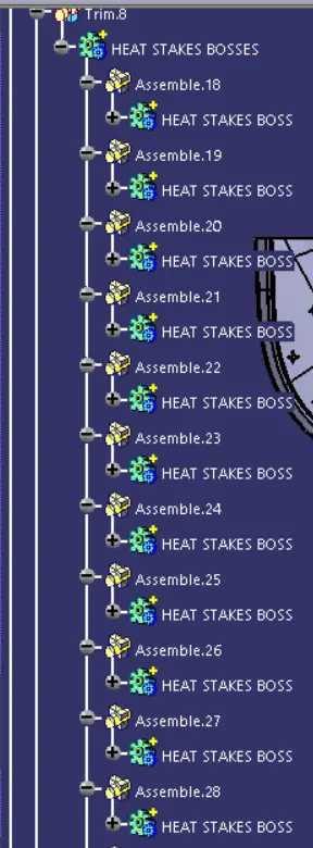
Draft analysis on class A surface
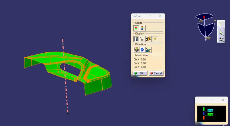
Draft analysis of closed surface
Procedure for creating tooling axis and side core axis
Tooling axis represents the opening and closing of the mold core and cavity during the manufacturing of the components. A plastic product designer should consider the best tooling direction to cutdown the cost of the component very less.
Method opted for creating tooling axis for the bumper are,
1. Check the best tooling direction for the given surface.
2. We can find out the best tooling direction by cross checking all the three axes.
Here we can find out that the best tooling direction for the door trim class-A surface is along Y-axis direction. The method I choose to create the tooling axis is first extract a surface and then create a point and using point direction option to create a tooling axis.
Procedure for doing draft analysis
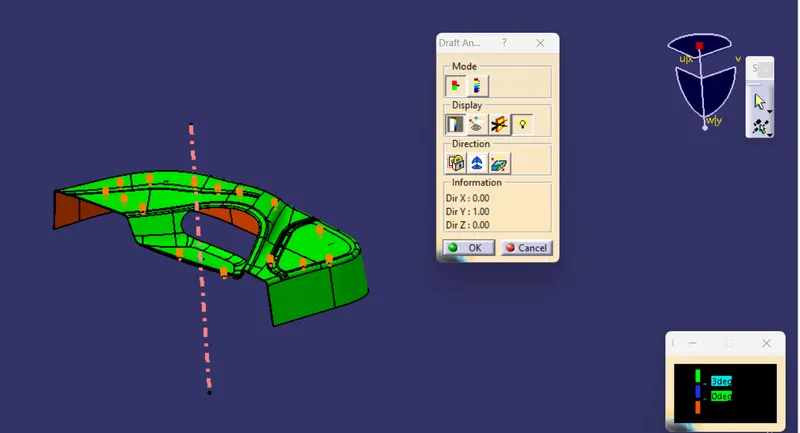
The Draft Analysis is a command enables you to detect if the part you drafted will be easily removed. This type of analysis is performed based on colour ranges identifying zones on the analysed element where the deviation from the draft direction at any point, corresponds to specified values. Draft analysis is done after determining the tooling axis, draft analysis is used to check whether the minimum draft (3 degrees) is maintained or not.
The procedure is as follows,
1. Change the part to material mode
2. Open the draft analysis from Insert menu
3. Then click on use the compass to define the current drafting direction and then drag and align the compass on the Tooling axis.
4. Then lock the draft direction and perform draft analysis by clicking on the component.
5. The green color shows positive draft, blue shows 0° draft and red indicates negative draft
Observations of draft analysis
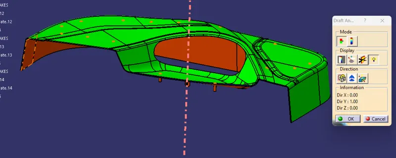
The red color area is clearing at 2° draft angle but not at 3°.