Week 9 - Project 1 - Door Trim Lower with Engineering Features
AIM-
Create the Door Trim Lower Plastic component through the given Class-A surface. To begin with, the tooling axis for the given Class-A Surface should be created meeting the requirements of the draft angle and at the end perform the Draft analysis on the model.
Create the Heat Stakes and the locators considering the design rules mentioned in the video for the door applique.
OBJECTIVES:
- Sketches
- Use Positioned sketch
- Sketches should be Iso-Constrained
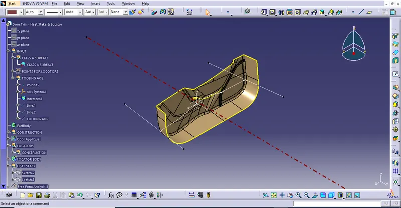
- Tree Structure
- Ensure Proper Tree Structure
- Geometrical sets should have a proper name based on the sketches present inside of it
- All the sketches should be created under the Geometrical set
- Report
- A detailed report should be done explaining the draft analysis and the tooling axis creation.
- An explanation should be given on the way of creating the tooling axis, particularly the Bisecting method
- References
- Use the given points in the model to create the locators and Heat stakes
- Refer to the below-given image for more details
DESCRIPTION:
- Sketches
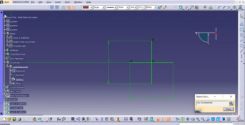
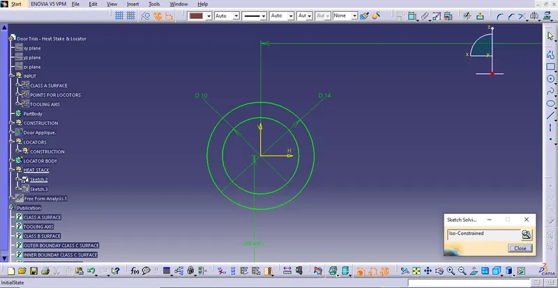
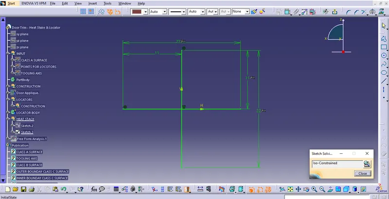
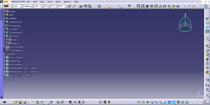
- Tree Structure
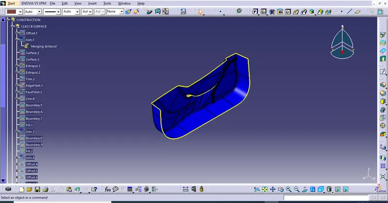
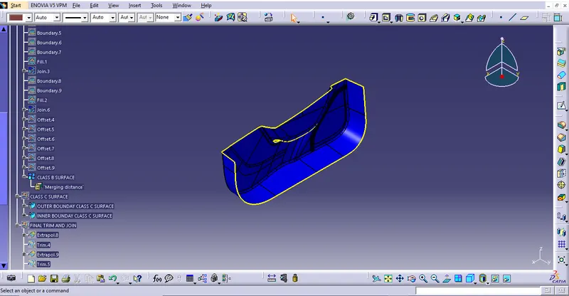
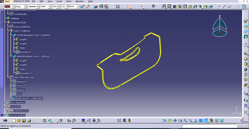
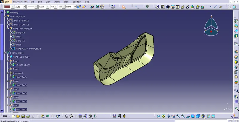
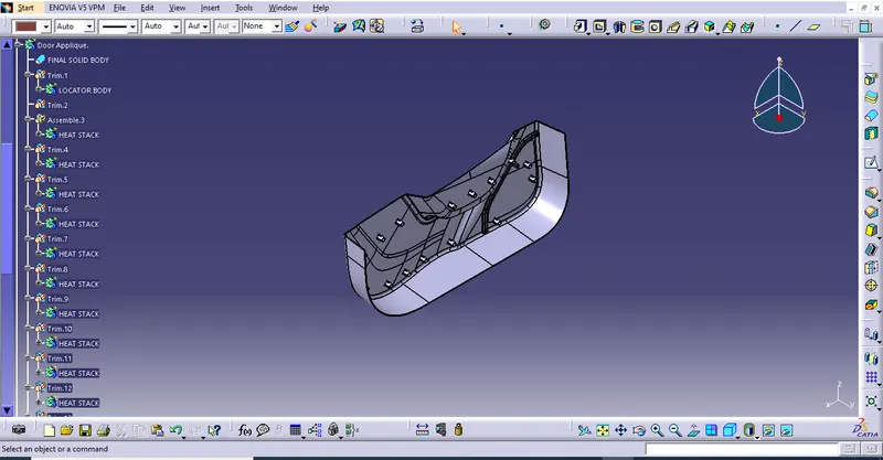
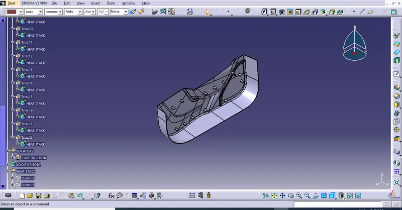
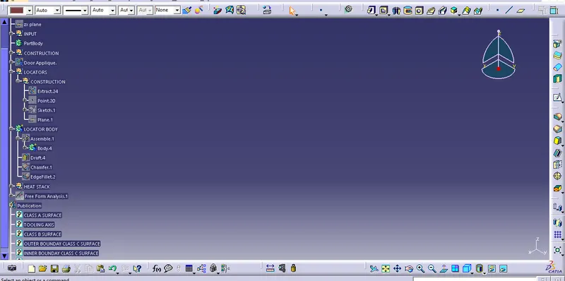
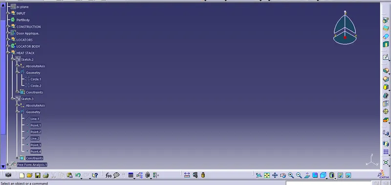
- Report
- A detailed report should be done explaining the draft analysis and the tooling axis creation.
- An explanation should be given on the way of creating the tooling axis, particularly the Bisecting method.
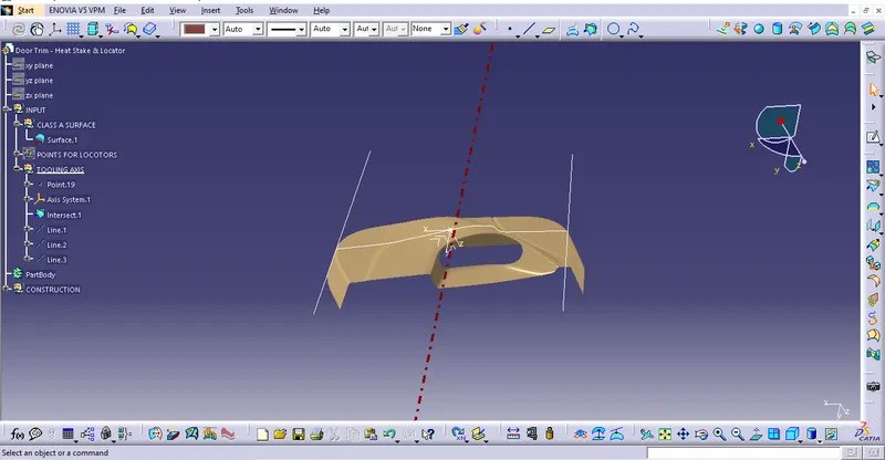
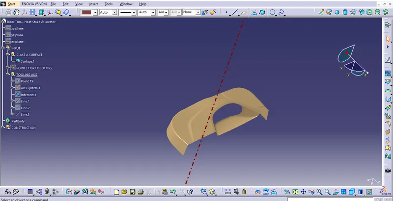
Tooling Axis creation:
It is defined as the direction in which the mould/core and cavity open. Selection of the direction of the tooling axis depends on the ease at which components can be easily ejected.
By analysing the component the most easily ejectable direction is somewhere close to the Z direction,(might be inclined to it) so we have made a sketch on the YX plane of Axis System) to create a bisecting line considering the 2 faces which might be difficult to be tooled.One more sketch is created on the YX plane of Axis System for considering the lone side face for tooling direction. In the sketch, a line is drawn with a suitable angle to the line. side face so that with the resultant tooling axis the side face is cleared.Then resultant tooling axis is created using the bisecting method.
Draft Analysis of Solid Model
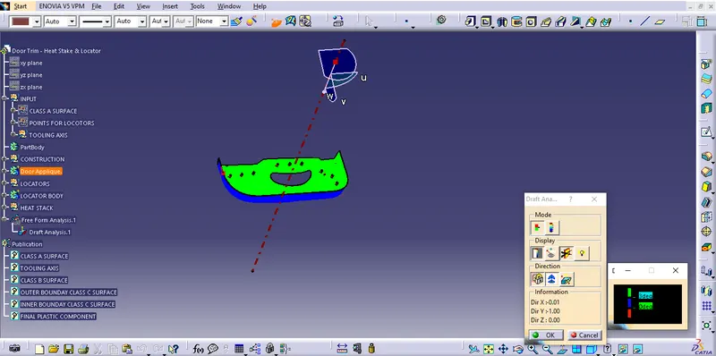
Same steps are followed to get the draft analysis of the solid part as in Class A Surface.
As we know minimum draft angle for the faces of the plastic component should be 3 degrees. So the value of 2.9 degrees (considering tolerance) is provided in the Draft analysis colour mode window Inside the colour scale, the GREEN bar shows the draft angle of 2.9 or above 2.9 degrees. The blue bar shows below 2.9 degrees draft angle the other limit being and the RED bar shows the negative draft angle. As shown in the image below all the top faces and side faces of the component are green, while the bottom faces are red. The line of demarcation between the green and red faces is the parting line which divides the core and cavity halves. The solid model has cleared the draft analysis successfully as shown in the image below.
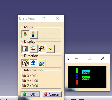
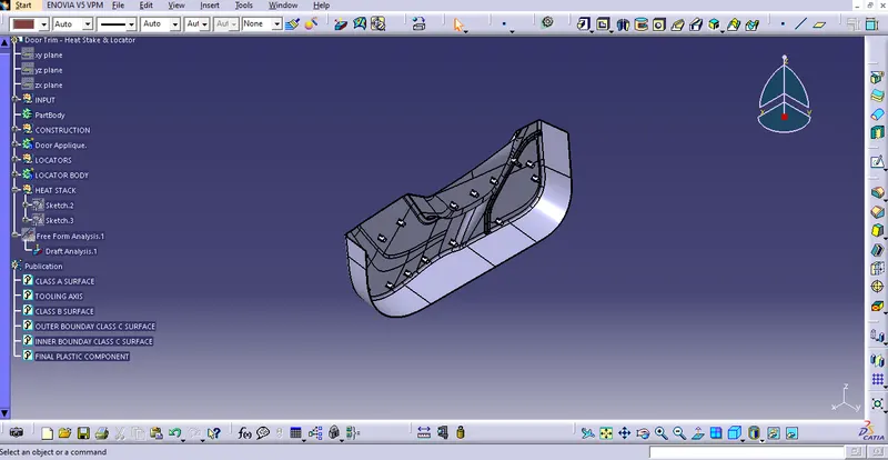
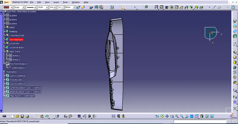
- Screenshots of the completed design in various orientations (Isometric, Front, Side, and Top View)
Isometric View
Front View
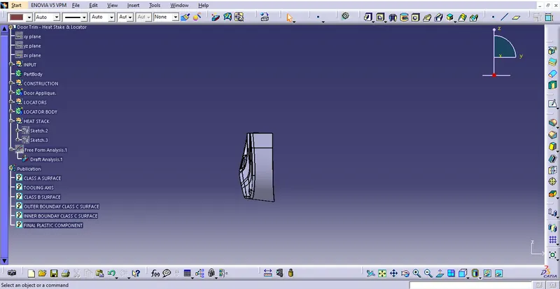
Side View
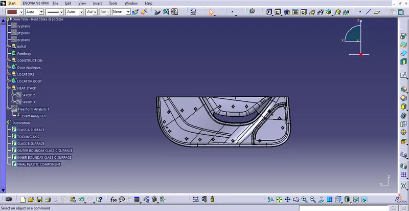
Top View
Conclusion:
As per the given class-A surface we have created the solid body and added heat stakes and locators and performed draft analysis on both the class-A surface and the final component.