Week 9 - Project 1 - Door Trim Lower with Engineering Features
Step 1 - Selection of tooling Axis.
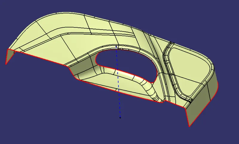
- The direction in which core and cavity open is tooling axis.
- After visualising Class A surface we can say that y-direction will tooling axis direction.
- Now I have checked faces of class A and the lower face is best for tooling axis because when seeing normal view of that face every face/part of class A surface is visible.
- Now i have extracted the face and made a point at cente of this extract.
- From point,I have made a line which is normal to surface.
- This is our tooling axis.
Step- 2 Draft analysis for CLASS A -Surface
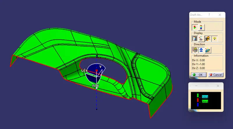
- Insert > Analysis > Features draft analysis
- Make sure it should be in material mode
- Now go to direction, and click 2nd option.
- Pick the compass and align it with the tooling Axis and click on the lock .
- Now click on the class A surface,we will see a green colour surface.
- So we have performed draft analysis on Class A- Surface and all face are clearing the surface.
Step-3 Creation of Class-B Surface
Class B will the surface we will add engineerning feature, to create Class B, I have follow below steps
- First offset Class A Surface 2.5 mm.
- After seeing offset we will see that some fillets are not there in the offset.
- I have use MULTIPLE EXTRACT/MULTISECTION command and selected the fillets, in which i have to work.
- After selecting fillets , click on complementary mode.
- Select Multiple extract and use disasssemble , to divide surface into 4 parts, in below different colour 4 surface after disassemble.
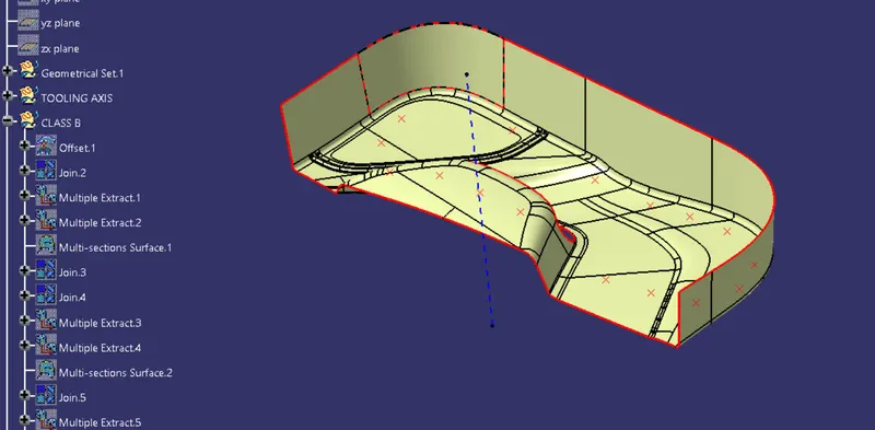
- Offset Class A by 2.5mm
- after offset some of the fillet patches were not properly offset.
- So to resolve it i used MULTIPLE EXTRACT & MULTISECTIUON commands and complete CLASS B surface.
Step-4 Class-C Surface
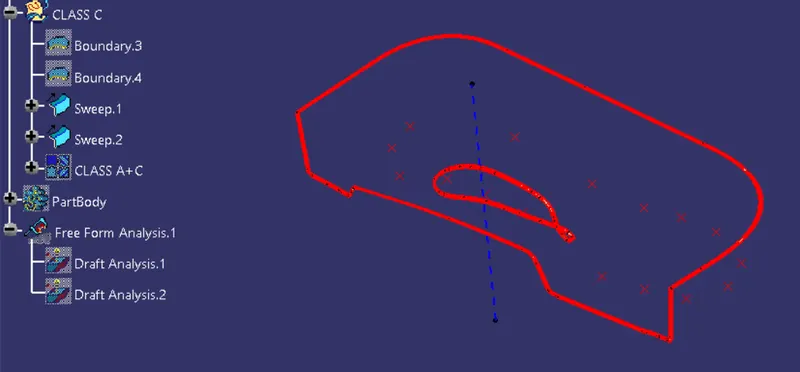
- Use bondary operation and extract the ouside boundary.
- And now i used sweep using reference surface.
- I have taken angle 90 degree and angular sector 1.
- Join both C surface, This will be our class C surface.
- Join this C surface with Class A surface and after that trim it.
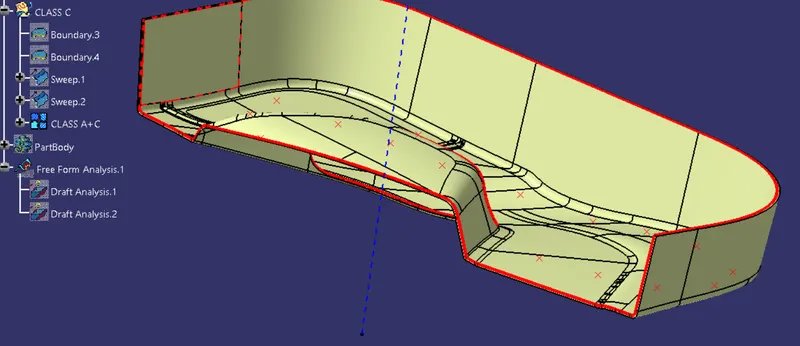
CLASS A+C.
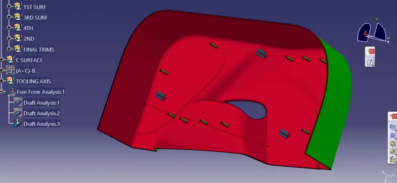
Step -5 Draft analysis report for the final plastic component with engineering features
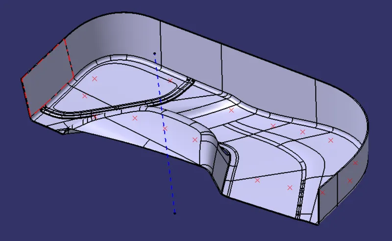
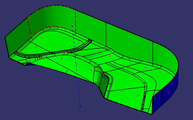
Draft analysis tell whether our component is manufacturable or not, if it's green it clears but if it's red means the surface is not clearing.
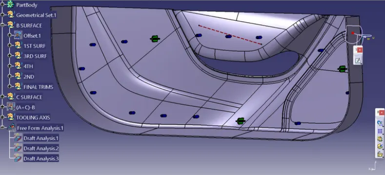
HEAT STAKING- It is method of assembly , in which plastic (theromplastic polymer) stud or boss is heated and then cooled to assemble/lock with other components.
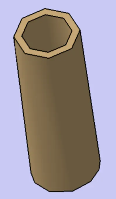
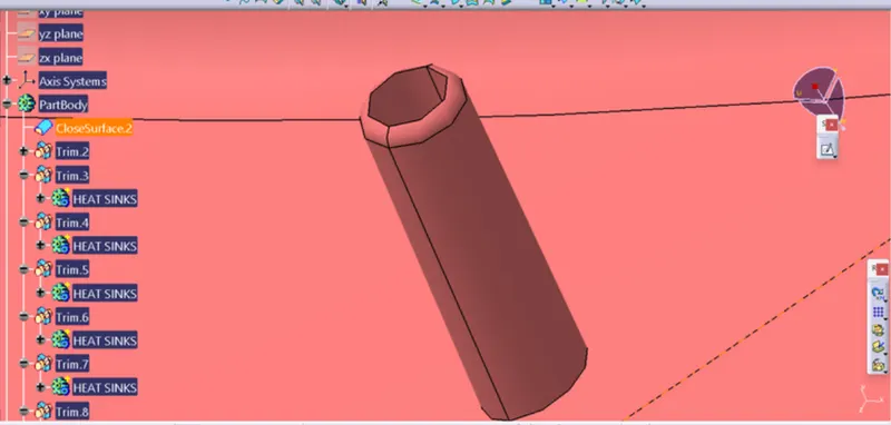
Advantages are
- Simplification of machinary
- Does not require extra parts for fixing
- Reduce cost,etc.
To make Heat staking we need to fellow following steps-
- Since we have got some points as input
- I have extracted 1 face
- And made a plane tangent to extract surface, at any given input point.
- Now draw a sketch
- these circle will be our inner and outside wall.
- Now in part workbench pad them
- I have taken diection as tooling axis.
- Now apply the outside as well inside draft separatly.
- this is our 1st Heating stake, now using translation feature i have made on other 13 points.
- So first copy the heat stake body and right click on "Door Trim - Heat Stake & Locator" and select on paste special.
- And click on "As result with link" and press OK.
- Now use translation and using point -point select the end point, as the point where we want to place the heat stake.
- Now after doing for all 14 heat stake , union trim with main body.
- And remove unwanted parts.
- Apply the fillels and Heat stakes are ready.
Step-6 LOCATORS
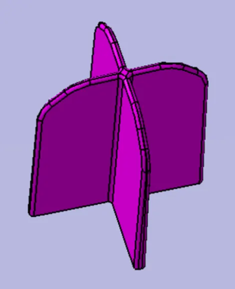
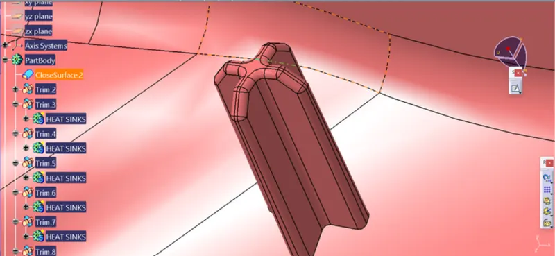
- For locator we will use same plane which was used for heat stake,
- So draw a sketch
- Now we wiil pad it,also tick on thick, taking direction as tooling axis.
- I have taken thickness of components as 1.2mm
- Provide the draft and take draft angle as 0.5 degree, and provide champer
- Now provide fillets , and our locator is ready.
- To create other locator i have used translate feature and repeated same step as for heat stake
- Now union trim both the locator with main part.
The height of our locator should be more than heat stake.
Average Height of Locator =21mm
Average Height of heat stake = 14.3mm
Step -7 Draft analysis report for the final plastic component