Week 9 - Project 1 - Door Trim Lower with Engineering Features
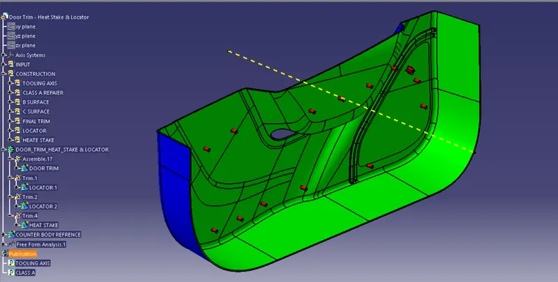
Aim: Create the Door Trim Lower Plastic component through the given Class-A surface & Create the Heat Stakes and the locators considering the design rules .
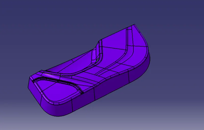
Input Class A surface:
Draft analysis report for both the given Class-A surface and the final plastic component:
DRAFT:
Draft angle is nothing but providing some tapered portion to the part for easy removal of the component from the mold during manufacturing. This is especially done in the case of plastic component design having a complex shape. Mostly the 3-degree draft angle is provided but it can vary depending upon the component which is to be designed
In our case of Switch Bezel design, the draft angle is 3 degrees the draft analysis is done during the design of the component to check the feasibility of the product.
Before providing a draft angle we need to decide on the tooling axis also known as the molding axis considering the faces which can cause issues while manufacturing.
TOOLING AXIS :
It is nothing but the direction in which the mold opens and closes the draft angle needed to be provided by considering this tooling axis.
We can create a tooling axis by using the bisecting method.
BISECTING METHOD:
This method is used for the generation of the tooling axis for that purpose first we need to decide the direction of molding and then we create one dummy tooling axis for the reference to the purpose.
In this method, we select the surfaces which can create problems and take intersections in the x and y-direction. By using these curves we draw two lines and then draw a bisecting line from these two lines in the x-direction and y-direction.
If it is done in x-direction then it is called a tooling axis clearing x-direction and if in y then tooling axis clearing y-direction.
After completing this we need to draw a final line bisecting this two tooling axis in the X and Y directions to get our final output.
Class A surface draft analysis:
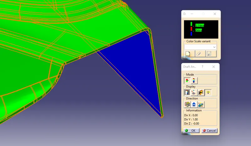
3 Degree.
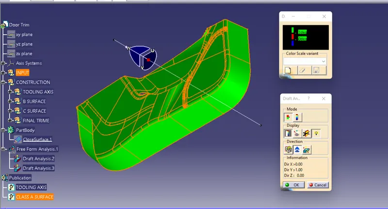
In the above images, the draft analysis of the Class A surface has shown the draft angle should be more than 3 degrees and this can be clearly observed from the above images that the surfaces have an angle of more than 3 degrees.
Solid component draft analysis:
3 Degree.
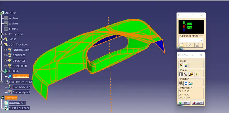
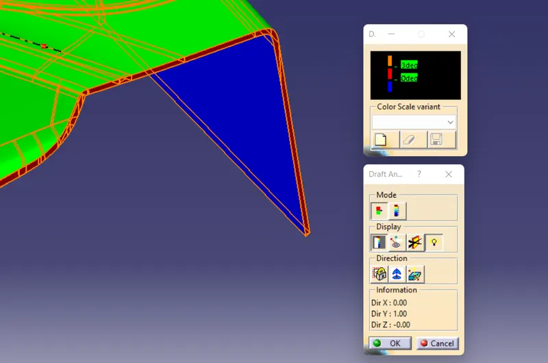
2.7Degree.
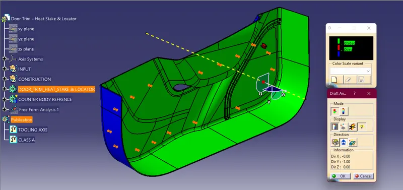
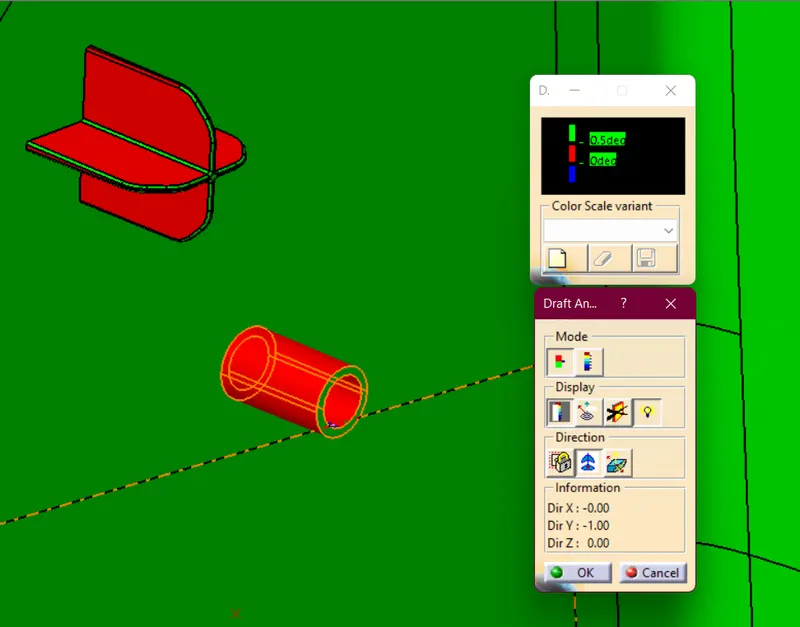
But in solid component draft analysis in which green color surfaces shows that they are having an angle of more than 3 degrees but some surface in red color shows it is less than 3 degree that is having an angle of 2.7 degrees. These are the results of the draft analysis which are very crucial for determining the feasibility of the product.
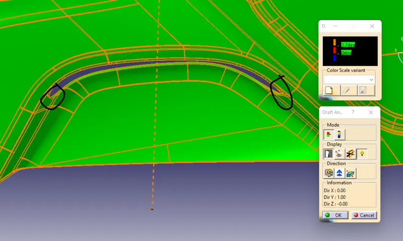
Inside the colour scale, the GREEN bar shows the draft angle of 2.7 or above 2.7 degrees. The Red bar shows below 2.7 degrees draft angle the other limit being and the blue bar shows the negative draft angle. As shown in the image below all the top faces and side faces of the component are green, while some bottom faces are blue or two spot are red.
1) Locators creation
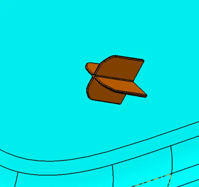
Locators are used when assembling sub parts and are very useful engineering feature for easy way of locating the position of the parts to be assembled
I have created two 4-way locators for the given door trim design.
Design procedure
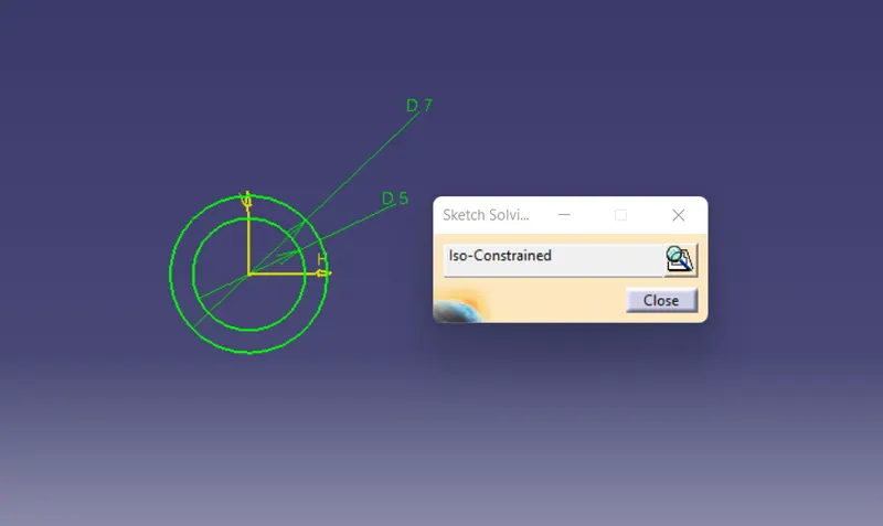
- Create positioned sketch and make required iso-constrained sketch.
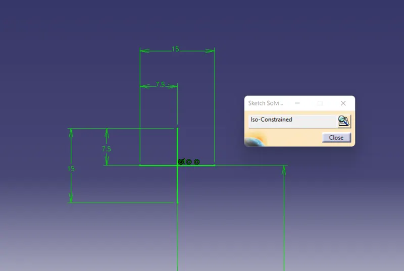
- Pad the sketch profile with reference to the tooling axis. Locator’s height should be more than that of heat stakes.
- Create chamfer of 3*45 degree on the to face for the easy entry of the locators to the holes.
- Draft angle 0.5 degree is given to all the faces.
- 0.25 mm edge fillets are given to all the edges.
- Finally, using union trim Boolean operation, trim the locators with the door trim body part.
2) Heat stakes creation
Heat staking method is commonly used in OEM to assemble door trims, instrument panels etc.
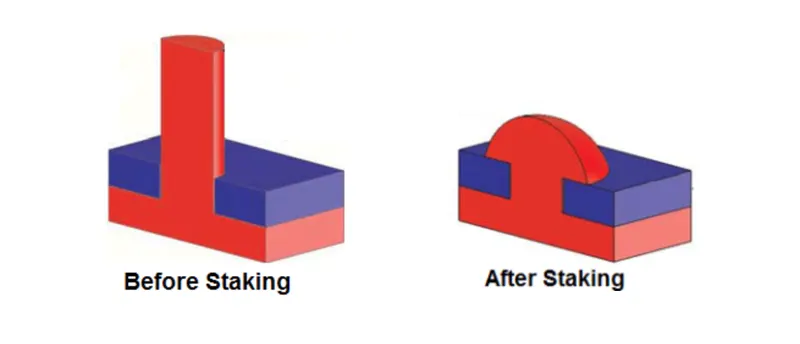
Heat staking also known as thermoplastic staking is the process of joining two dissimilar materials together. In heat staking we use local heating and cooling to raise the temperature of plastic components and allow plastic reforming to be carried out. This reforming can be used in a wide variety of applications.
Heat staking can be performed using wide range of thermoplastic materials including polypropylene, ABS, polycarbonate and many others. The integrity of a thermal staked assembly depends greatly upon the geometric relationship between the boss and the thermal tip.
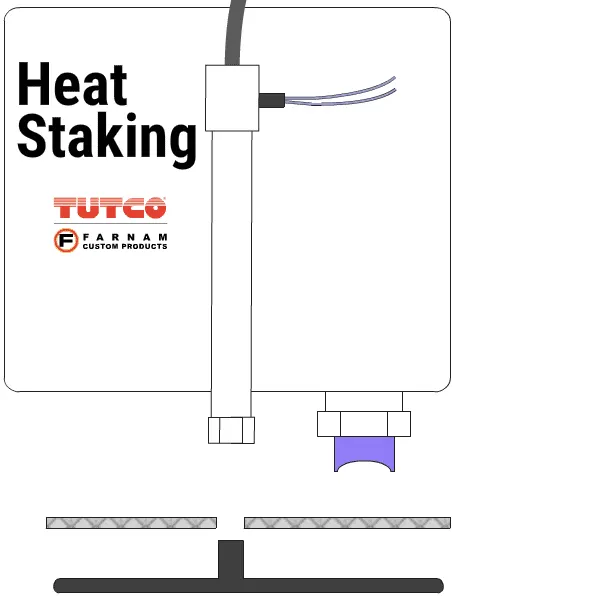
The heat staking tip is brought into contact with the thermoplastic part to be reformed. The heating tip is then heated by direct electrical heating within the tip for a short period of time. The heated tip softens the plastic material and forms the melted plastic into the shape of the tip.
The below image shows a simple animation of heat staking process.
Heat stake Design procedure
- Using positioned sketch, create sketch of the heat stake profile.
- Pad it with reference to the tooling axis.
- Heat stake height should be lesser than the height of locators provided.
- Thickness should be 40% of the component main thickness to avoid sink marks on the A surface.
- Provide draft angle of 0.5 degrees on both inside and outside walls of the heat stake.
- There should be minimum 50 mm gaps between each heat stakes.
- Create more heat stakes by special copying option and translate it to desired points.
- Then union trim them with door trim part body to get the final component.
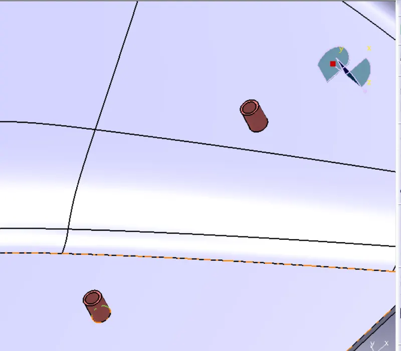
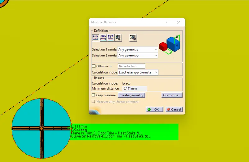
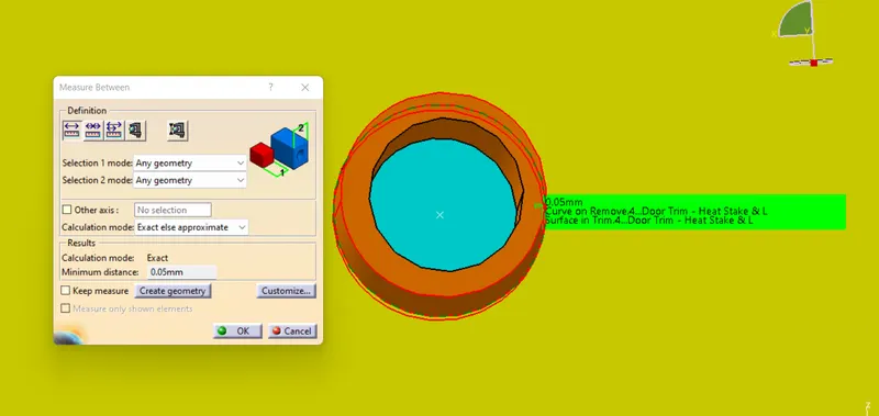
Final Door trim Body with the required engineering features
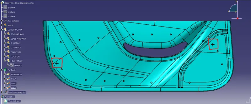
Heat Stakes and the locatorsTooling Axis:
FINAL COMPONENT: