Week 9 - Project 1 - Door Trim Lower with Engineering Features
AIM: Creating the Door Trim Lower Plastic component through the given Class-A surface and creating the heat strakes and locators as given in the question.
Class A surface: The Class A surface is given by Class A engineer we have to create a plastic component. I have taken the thickness 2.5mm
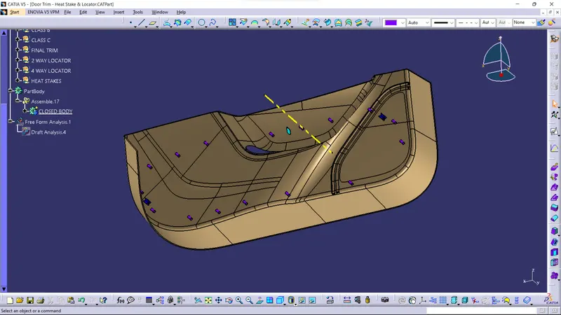
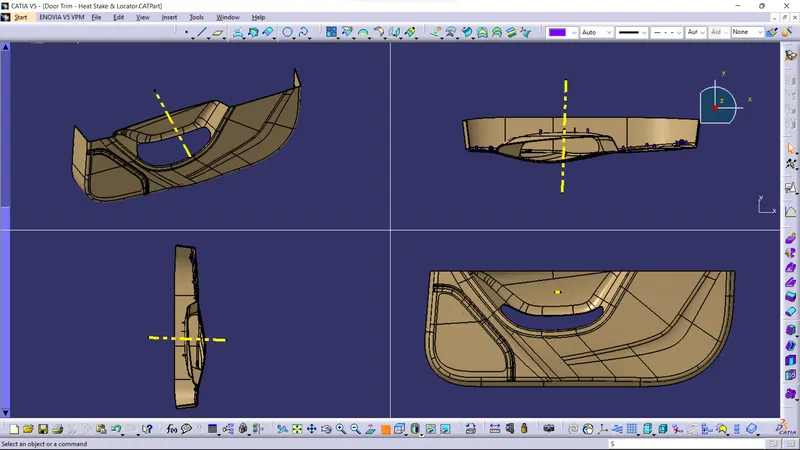
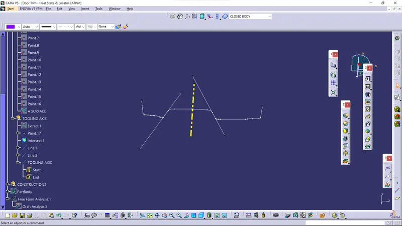
Creation of Tooling Axis: create a point on the A surface and take intersection of A surface with XY axis. using bisecting method create a tooling axis, The yellow line is the Tooling axis.
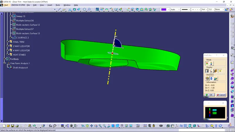
Draft analysis of class A surface: I have analysis the Class A surface with the tooling axis giving 3 deg as draft. it is clearing all the surfaces.
Creation of B surface: To create B surface offset the A surface at a distance of 2.5mm. There will be some gaps fill it using extrapolate and multisection method. and at last, give the fillet value.
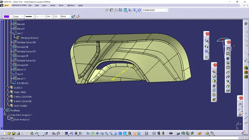
Creation of Class C surface: To create Class C surface Extract the edges of A surface and by using with reference surface and with draft direction respectively create sweep.
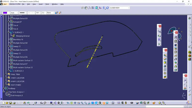
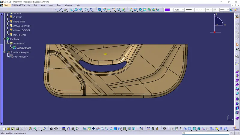
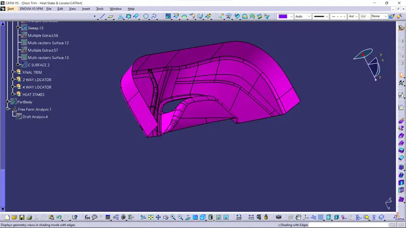
Final Trim: I trimed C surface with B surface and it is now B+C surface. then i joined class A surface with B+C surface. and this is final product. The below image is of final component
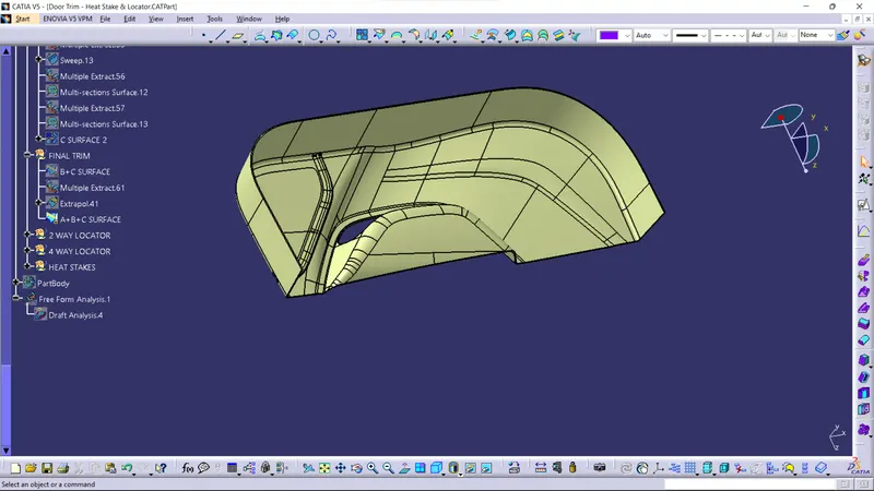
then i inserted the part body and used close surface command and closed the final component.
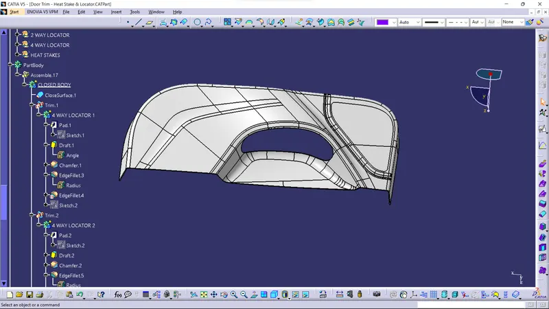
Creation of locators and heat stakes:
Then creating the Heat Stakes and the locators considering the design rules
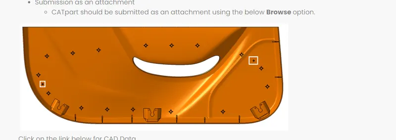
In cad they have given the Heat stakes reference point, and i have created 3 points for 4 way and 2 way locator.
First i created the 4 way locator sketch and i have pad it with 20mm height and 1.3 thick and given minimum draft and fillet. and then i used point to point translation and copied it. then i union trimmed it with main body.
second i created 2 way locator sketch and pad it same as 4 way locater and union trimmed it with main body
third i used given reference points to create heat stakes . i padded it and given the minimum draft and fillet then i used point to point translation and copied all the heat stakes. and assembled all the heat stakes in one body and union trimmed it with main body.
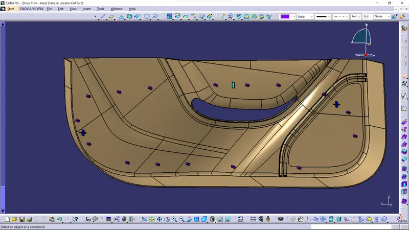
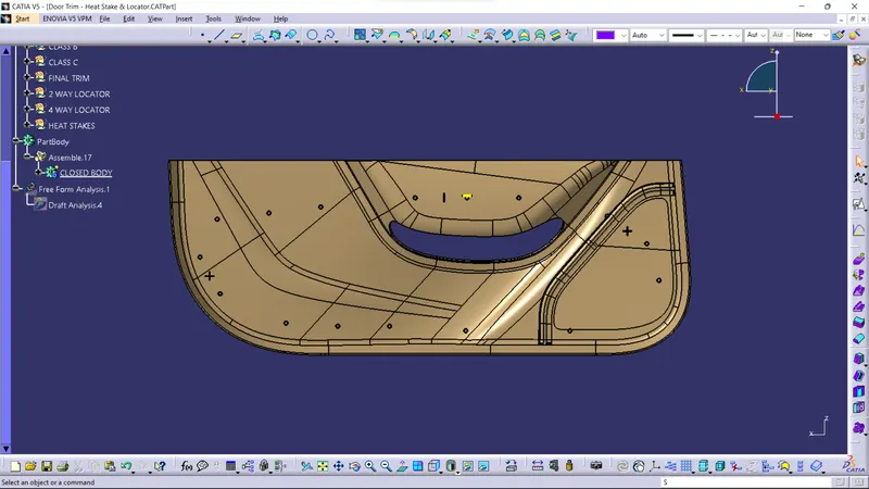
The above image shows the location of locators and heat stakes.
Draft analysis of the final product:
First with 3 deg draft analysis for main component. Then i used 0.5 deg draft analysis for locators and heat stakes. The below image is of draft analysis.
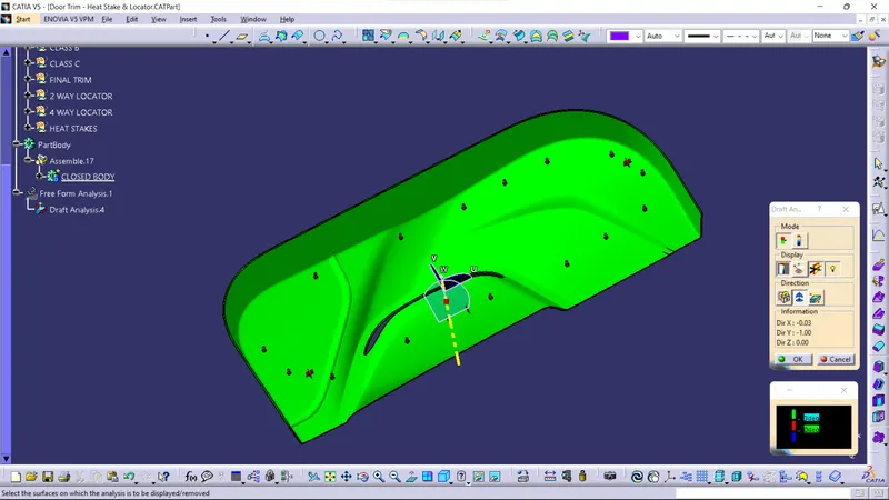
in this image the draft is 3 deg so the main component will clear, the heat stakes and the locators will not clear because for them the draft is minimum 0.5 deg.
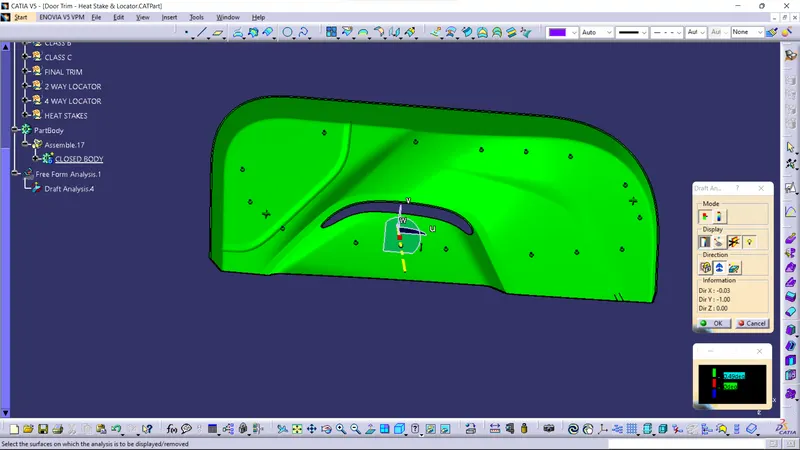
In this image the draft deg is 0.5deg but it is clearing with 0.49 deg draft.
the analysis for the main component is clearing.
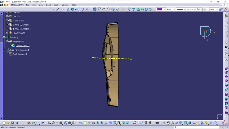
Different views: