Week 9 - Project 1 - Door Trim Lower with Engineering Features
Input:
The input was given as Class A surface.
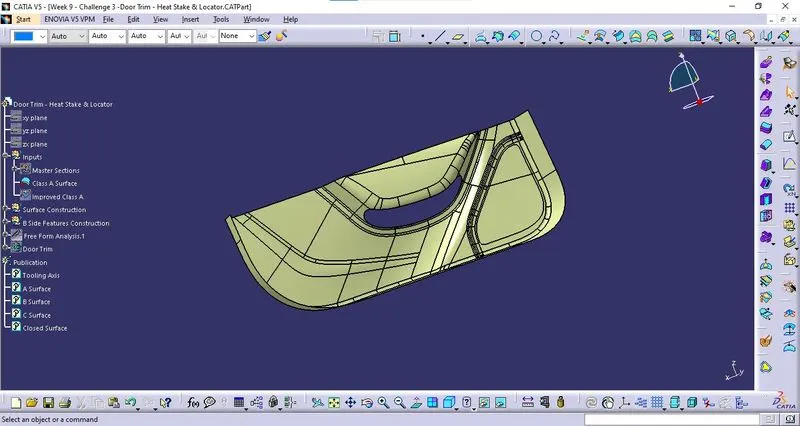
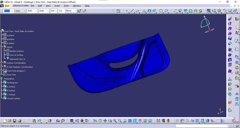
Improved Class A:
The Class A surface had some hitched and that was repaired.
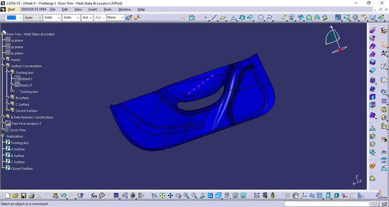
Tooling Axis:
The component has walls that are perpendicular to the base of the component. Since the natural tooling axis was taken, (i.e) the axis normal to the base is taken as the Tooling axis.
Draft Analysis of Class A:
Draft analysis is done on the Class A Surface with respect to the Tooling Axis created.
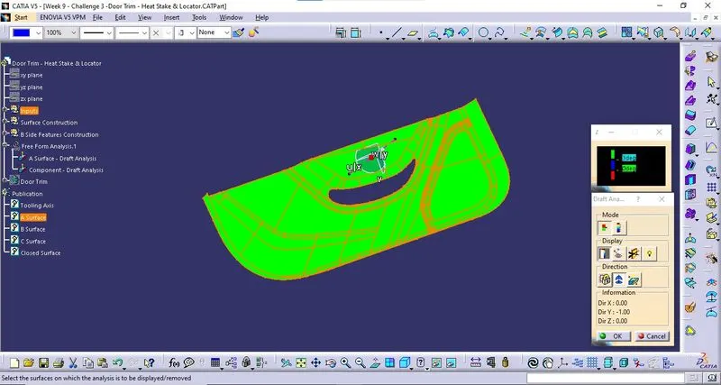
The draft angle is maintained at 3 degrees.
Class B Surface:
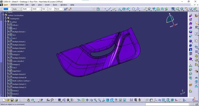
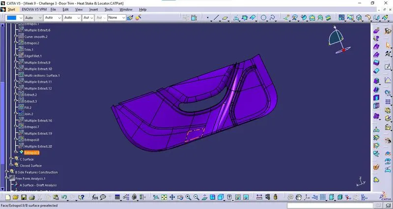
Class B was created by offsetting Class A to the thickness of the component, (i.e.) 2.5 mm. The imperfect boundaries are repaired and joined into a single surface and B Surface is formed. The commands used here are Offset, Fillet, Untrim, Join, Multi Section Surface, Split, and Extrapolate.
Class C Surface:
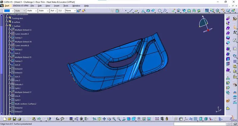
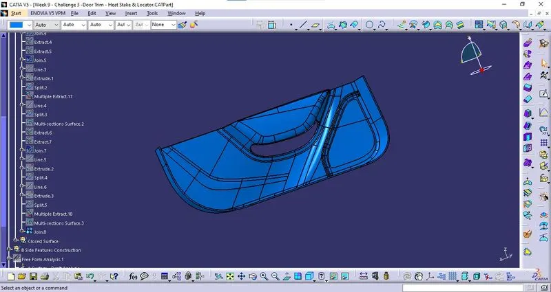
The boundary is created on the Class A Surface and a sweep was done with the boundary as a guiding curve and Class A Surface as a reference surface at 90 degrees. This sweep is then joined with the Class A Surface to form C Surface.
Closed Surface:
In the final stage of the surface creation, The Class A Surface and Class B Surface are trimmed together to form an appropriate closed surface.
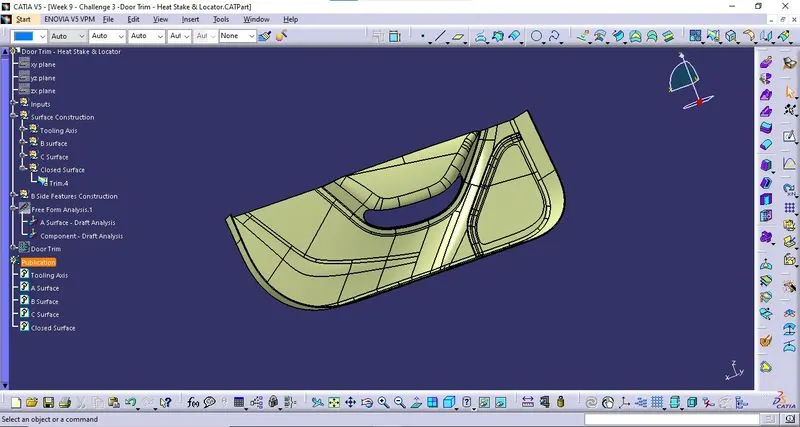
Part Body - Door Trim:
The part body is created using the close Surface command in Part Workbench with Closed Surface as the reference surface.
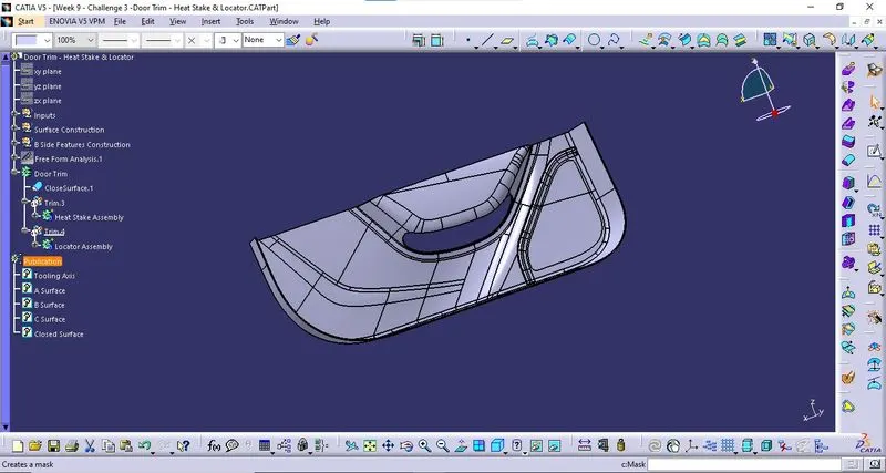
B Side Features:
Heat Stake Design:
Heat Stakes are designed as per the design considerations and located at the points provided in master section.
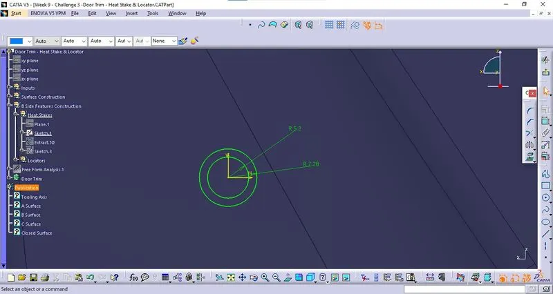
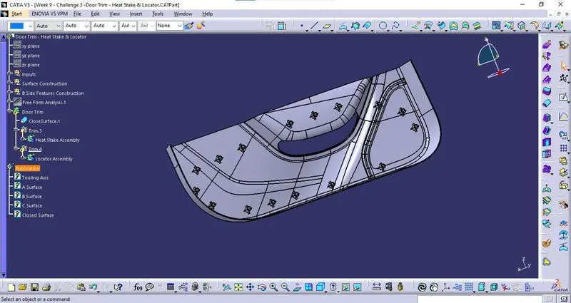
The heat stake is designed with a sketch and is initially assembled inside a Body called Heat Stake Assembly and then the feature is combined with the part body using Boolean Operation
Locator Design:
Locators are designed as per the design considerations and located at the points in the question.
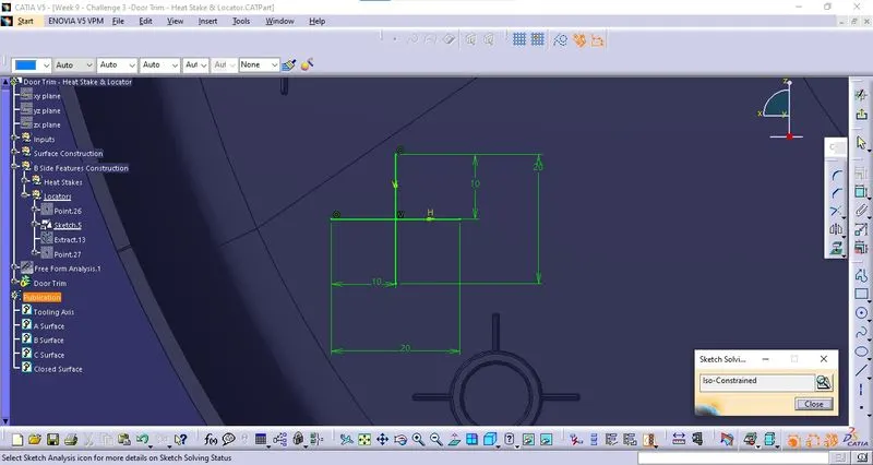
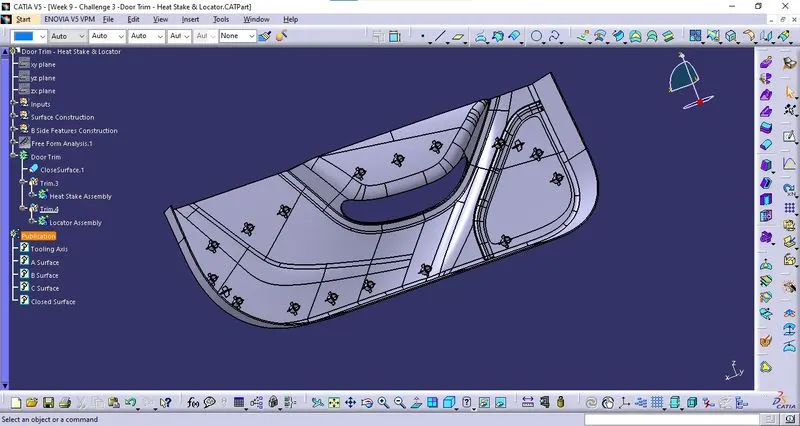
The locator is designed with a sketch and is initially assembled inside a Body called Locator Assembly and then the feature is combined with the part body using Boolean Operation
Draft Analysis - Component:
Component:
Draft analysis is done on the Component with respect to the Tooling Axis created.
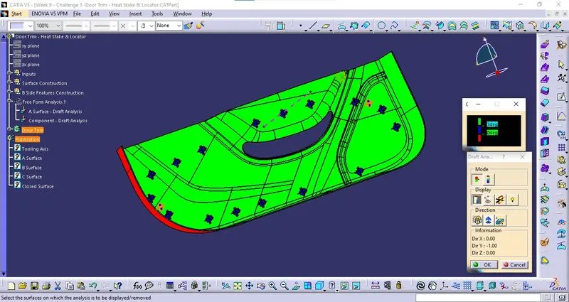
The minimum draft angle was maintained at 3 degrees for the clearance of components.
Component with B Side Features:
Draft analysis is done on the Component with respect to the Tooling Axis created.
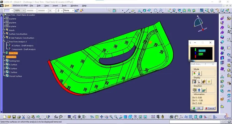
The minimum draft angle was maintained at 0.49 degrees for the clearance of B Side Features in components.
Final Component with B Side Features:
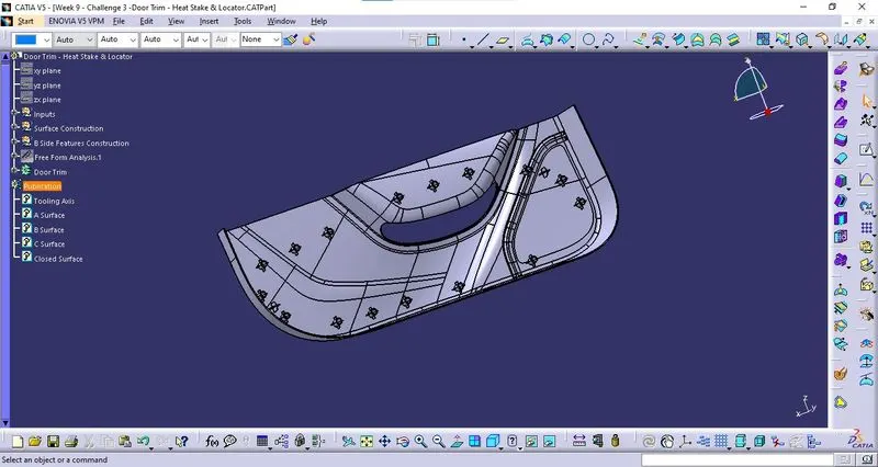
Isometric View:
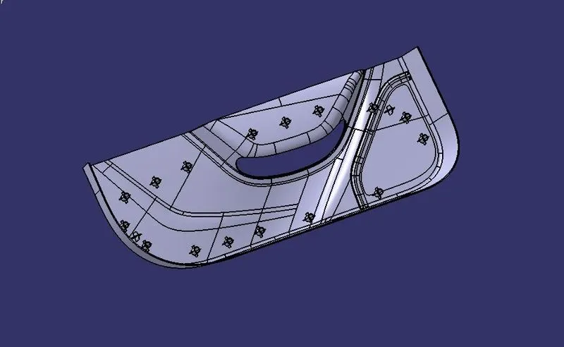
Front View:
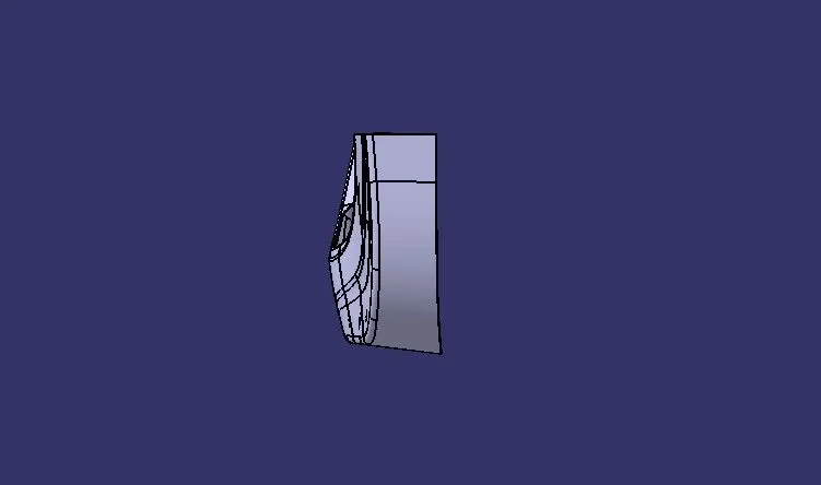
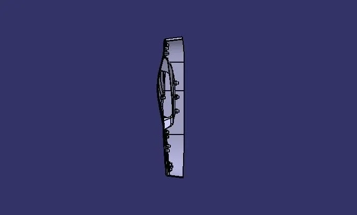
Side View:
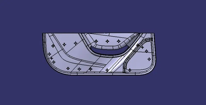
Top View:
Publication:
During this process of designing the Component, The Objects which are used frequently are published for ease of operation. Published Objects are,
- A Surface.
- Tooling Axis
- B Surface
- C Surface
- Closed Surface