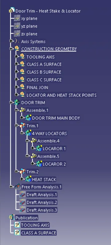
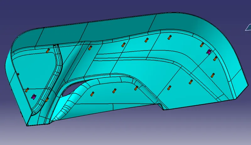
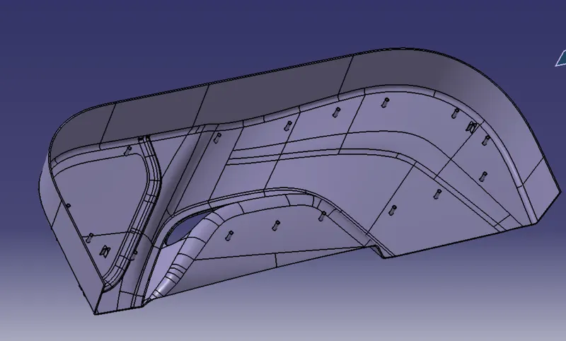
Week 9 - Project 1 - Door Trim Lower with Engineering Features
AIM
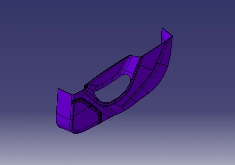
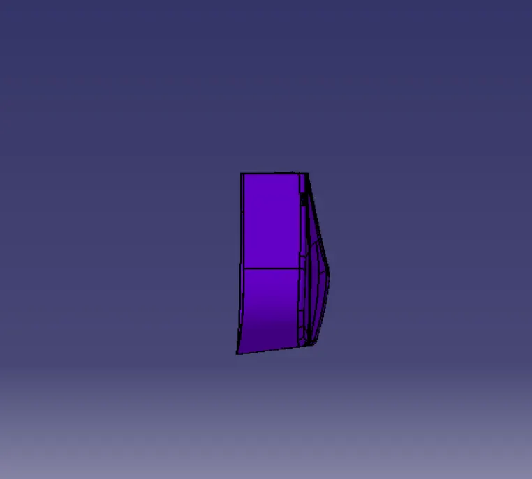
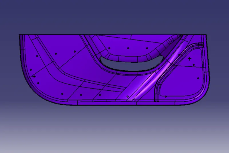
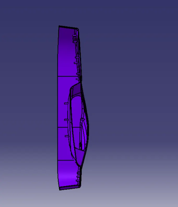
To make a full solid model from the provided lower door trim A surface and create locator and heat stacks.
INTRODUCTION:
CATIA:
It means Computer-Aided Three-Dimensional Interactive Application. It is computer aided designing software. This is software which is used to design 3D models with different workbenches.
CLASS A SURFACE:
It is surface which is made by the designer. It is aesthetic surface and usable outside futures are on this surface.
CLASS B SURFACE:
It is bottom side surface of class A surface. It is made by class A surface. It is formed with thickness distance from class A surface.
CLASS C SURFACE:
It joins the both class A and class B surfaces. This surface is equal to the thickness of the component.
TOOLING AXIS:
- Class A surface or part is used to manually analysis which is best for tooling and create the axis perpendicular to the product. It is called tooling axis. Mould is open and closed by this axis.
LOCATOR:
It is used to fix or lock the model with another part. But it is not fully fixed with main part.one side is in moving. It is in Class B surface.
HEAT STAKS:
It is used to fix the model permanently. Rest of locator fixed side is fixed by it. It also in class B surface.
METHODOLOGY:
MAIN PART:
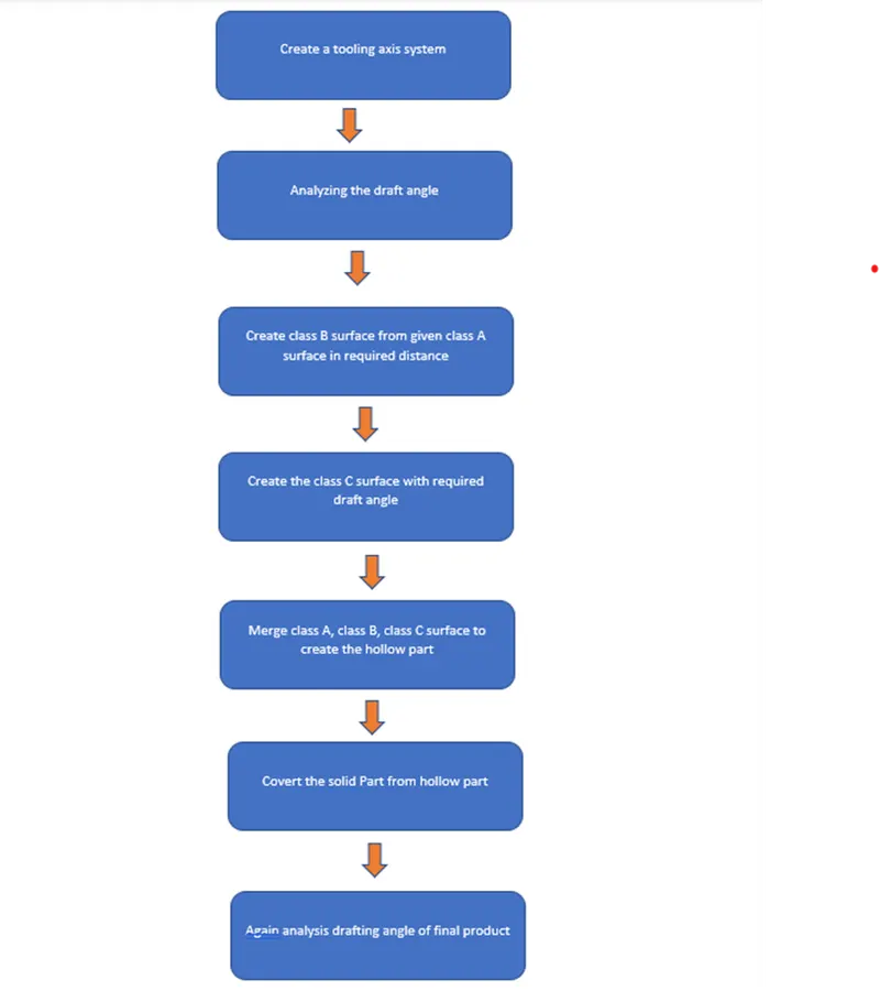
ENGINEERING FEATURE:
TOOLS:
- Extract:
This comment is used to create the required surface again. Which means copy the surface again for next operations.
- Un trim:
This tool is used to un trim the surface which means create the full surface of previous surface from current surface.
- Trim:
This tool is used to cut and eliminate the unwanted surface.
- Extrapolated:
This tool is used to increase the length of surface or area with the help of different option.
- Offset:
It is used to create the same surface again in required distance.
- Edge Fillet:
It is used to create sharp edges to round edges.
- Boundary:
It is used to form the boundary lines on opened surface.
- Sweep:
It is used to create the surface in required length from the profile.
- Join:
It is used to join the separate surfaces and create the single surface.
- Close (Part command)
It is used to create the solid part from closed hollow part.
- Curve smooth:
It is used to change the smooth curve from tangency curve.
- Fill:
Fill some gaps portion with this comment
- Blend:
Two bounty lines used to fill the gaps by this comment.
14.Split:
It is used separate the surface with the help of another surface as cutting tool.
- Pad:
It is used to extrude to create 3D part from 2D sketch.
- Thicken:
This comment is used to give thickness to the created surface.
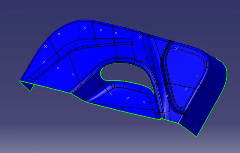
SURFACE A CLASS:
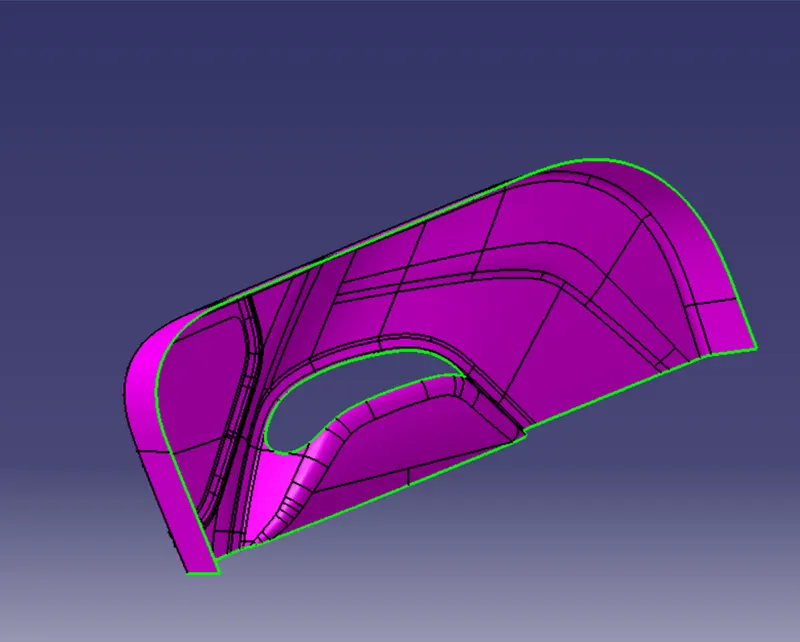
TOOLING AXIS CREATION:
- First create the class A surface and manually analysis and fix the direction of tooling.
- In this part two hole on the surface. So, we can directly take its perpendicular as the tooling axis because its most suitable for tooling axis. Carefully watch and take this axis with the help of all types of views.
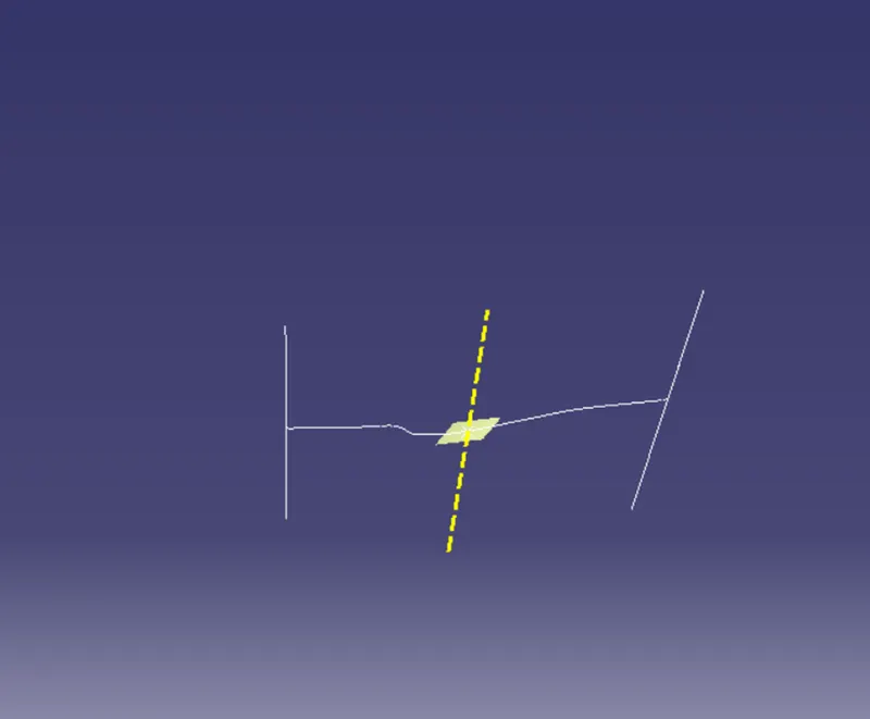
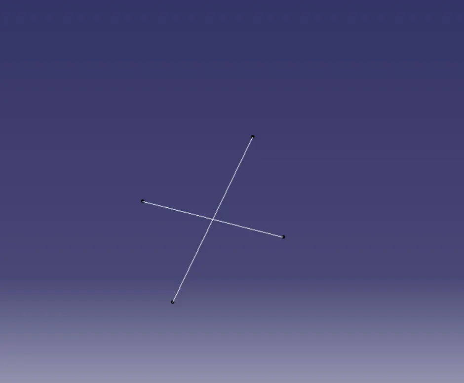
- First created the point on the surface and create new axis system.
- Then this intersect line is used to create the new lines on both wall lines. Then the both lines are used to create a bisecting line in tooling direction or It is zero degree drafting part, so we directly draw line through the line to form tooling axis.
- Change some appearance to this line like thickness, colour, dot lines. Finally, it is called tooling axis. It is published for frequent uses.
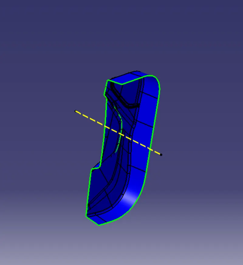
- Dog house is created by side core. So, we created separate tooling axis for dog house. Same method is used to create a tooling axis parapedicular to the main axis.
DRAFTING ANALYSIS:
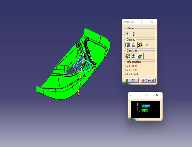
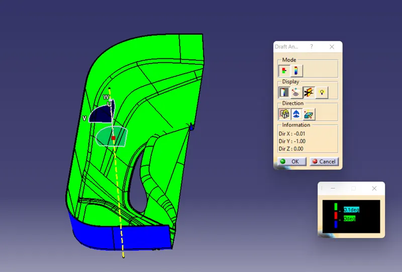
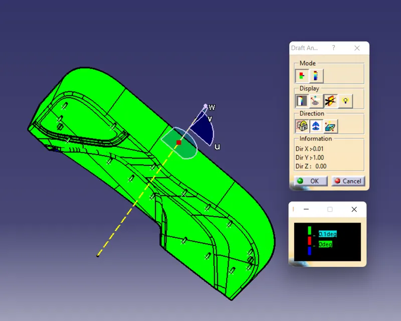
- Go to insert < analysis< feature draft analysis.
- Compass is fixed on the tooling axis.
- Then we click on the surface it showing different colour. This colour is used to analysis the drafting value of surface with the help of analysis table.
- It will show draft angle of class A surface.
SURFACE B CLASS CREATION:
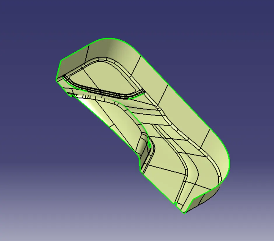
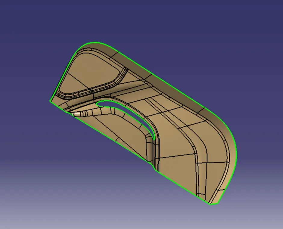
Following procedures are used to create surface B class.
- We directly offset the given bumper surface at 3mm distance inside with the help of offset comment fore b surface
- Some discontinuous surface filled with some comment like blend, fill, Mss etc.
- If we need any bounty expand with the help of extrapolated comment.
- Trim unwanted surface
- Finally, we got surface B class.
SURFACE C CLASS CREATION:
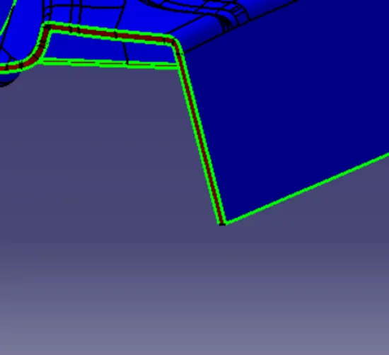
- Extract tool is used to create the boundary lines separately on side edges of class A surface
- Reference surface option sweep comment is used to extrude the created separate extract boundary lines at 90 degrees.
- Finally merge all sweep surface to get class C surface.
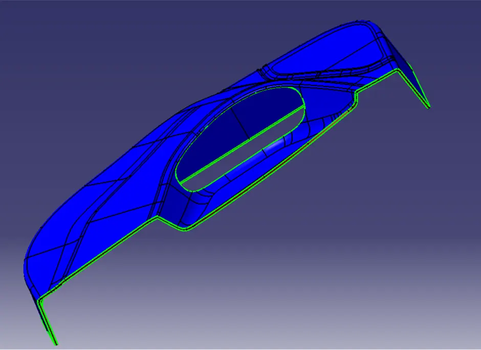
FINAL PART:
- Join command is used to join the surface A class and the surface A, C class
- Trim commend is used to trim class AC and B. They join themselves.
- Finally, we got hollow product.
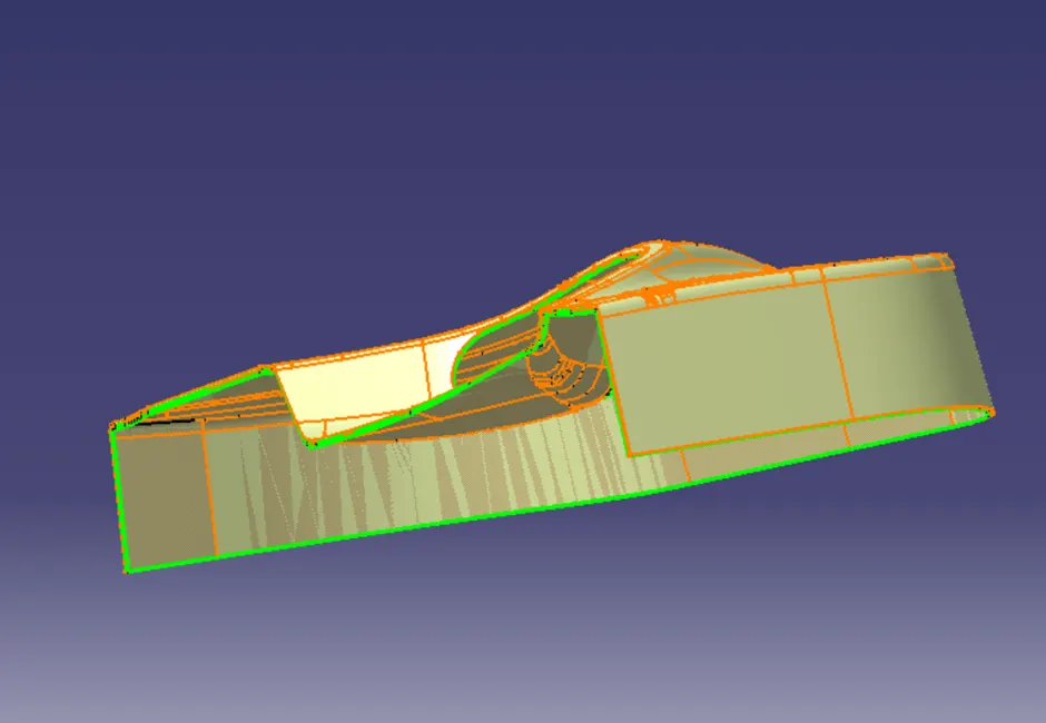
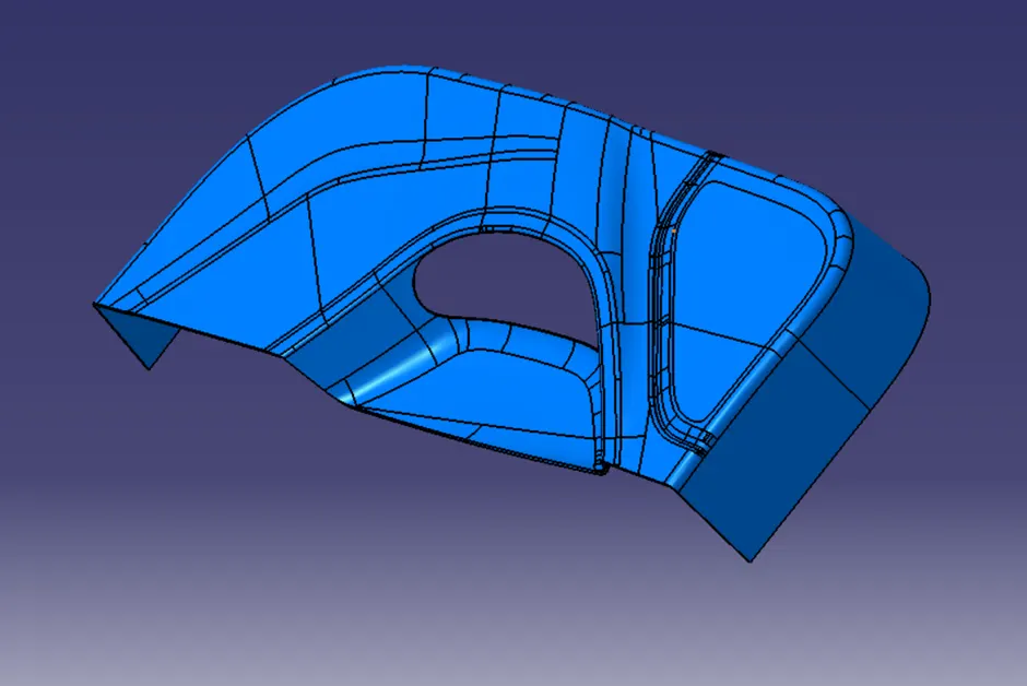
- In part bench close commend is used to get the solid model
- We give different colours to appearance and easily analysis different parts.
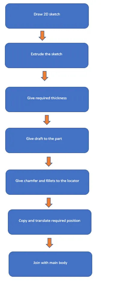
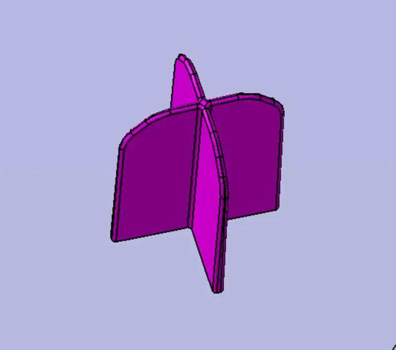
LOCATOR:
- First, draw 2d sketch for locator in required dimension.
- Extrude the sketch by pad comment
- Give draft to the part
- Then chamfer and fillets to the part.
- Translate tool is used to translate the copied parts in required position.
- Union trim is used merge with the main body.
HEAT STACKS:
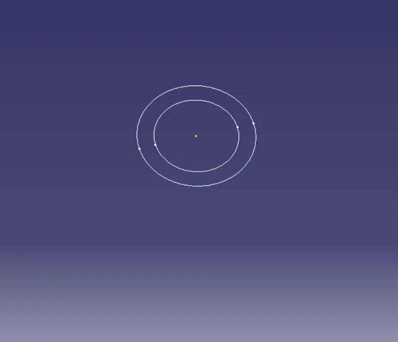
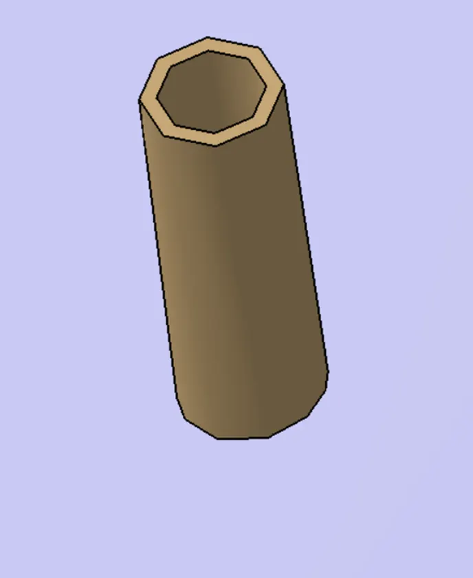
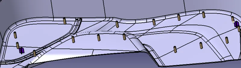
- Heat steaks are as well as bosses.
- Draw 2D sketch.
- Extrude the sketch by pad comment.
- Give draft to the part. Copied and pasted the required number of parts.
- Translate tool is used to translate the copied parts in required position. Positions are given oi the question.
- Finally, heat stacks are joined with main body by union trim comment.
DRAFTING ANYLYSIS:
If we want, Again, Same drafting analysis procedure is used to analysis the drafting angle of lower door trim. When we do draft analysis easily analysis the drafting mistakes and correct it. Draft is very important for moulding.
CONCLUSION:
Different commends are used to create the surface A class, B class, C class. Then join and convert the solid. Finally, B surface and solid part of lower door trim are created from provided class A surface and locators and heat stacks are successfully created by creating standered guide lines and drafting angle is analysed by CATIA software.