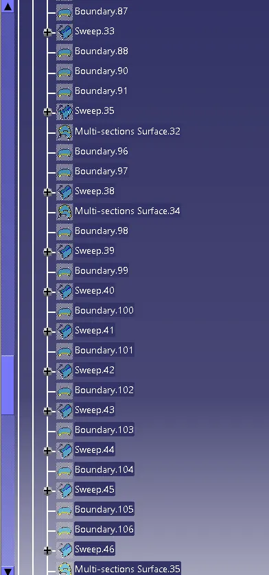
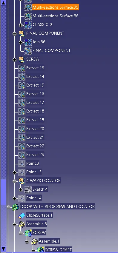
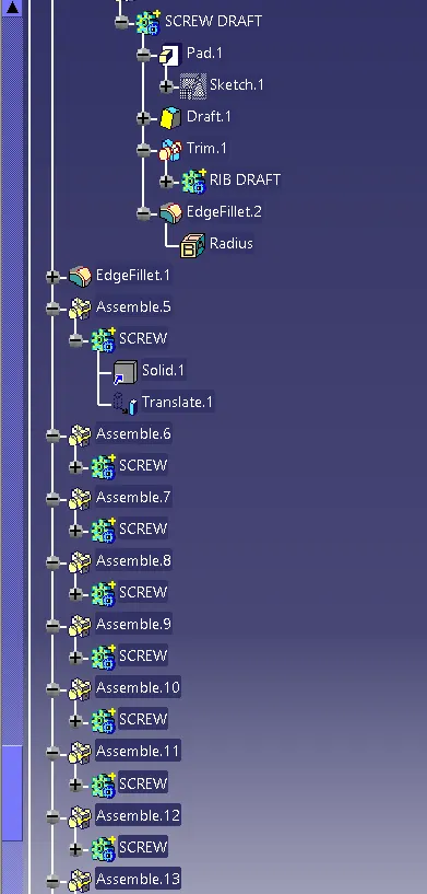
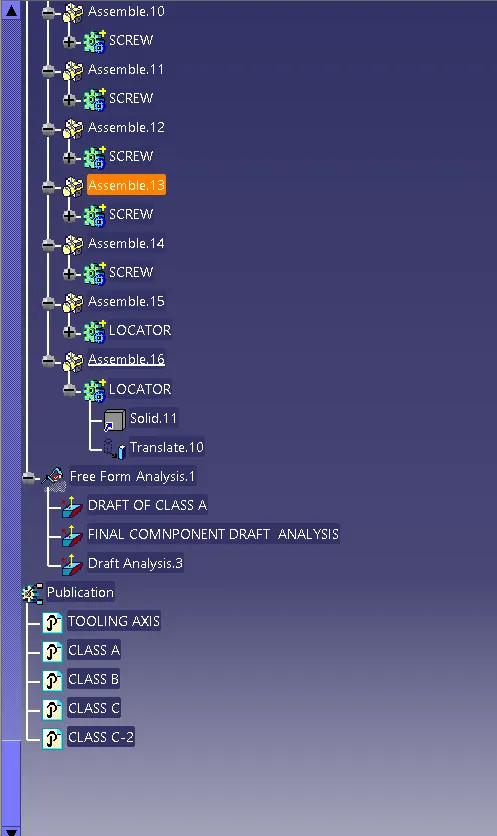
Week 9 - Project 1 - Door Trim Lower with Engineering Features
AIM:
To Create the Door Trim Lower Plastic component through the given Class-A surface. To begin with, the tooling axis for the given Class-A Surface should be created meeting the requirements of the draft angle and at the end perform the Draft analysis on the model.
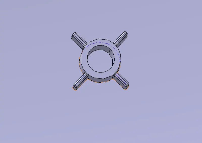
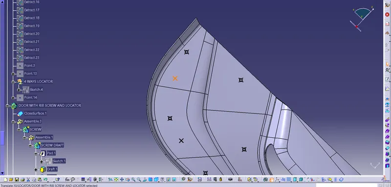
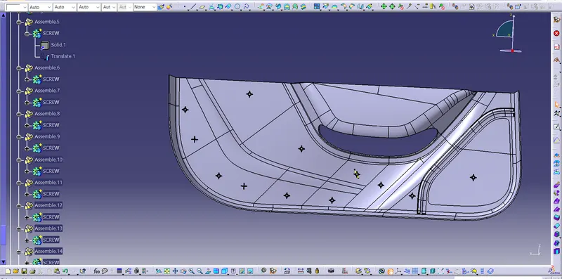
Create the Heat Stakes and the locators considering the design rules mentioned in the video for the door applique.
OBJECTIVE:
To create the Base Bracket Plastic from the given Class A.
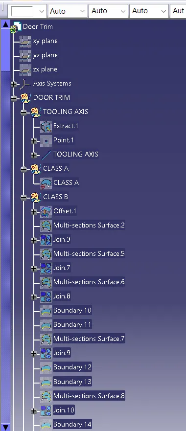
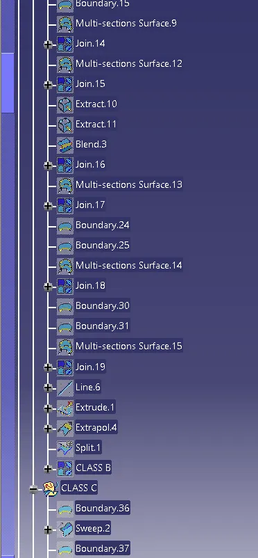
To ensure the all the sketch and tools in the Geometry set.
Give the proper name of the Geomatry set.
Create the Class B ad Class C.
The objective of the project is to design the car bumper and to do a draft analysis for it by creating the required tooling direction with the help of Bisecting method.
Create the Locator ans Heat stakes.
INTRODUCTION:
With draft analysis, you can verify draft angles, examine angle changes within a face, as well as locate parting lines, injection, and ejection surfaces in parts.
Drafts are defined on molded parts to make them easier to remove from molds. There are two ways of determining the objects to draft: either by explicitly selecting the object or by selecting the neutral element, which makes the application detect the appropriate faces to use.
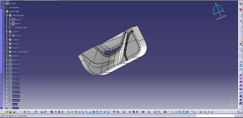
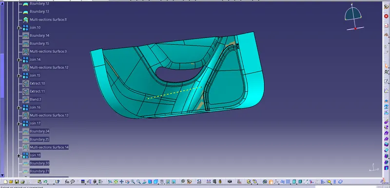
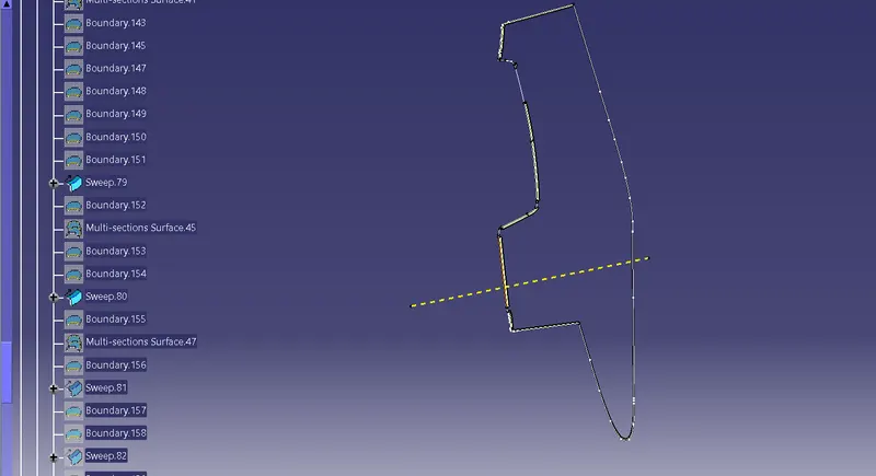
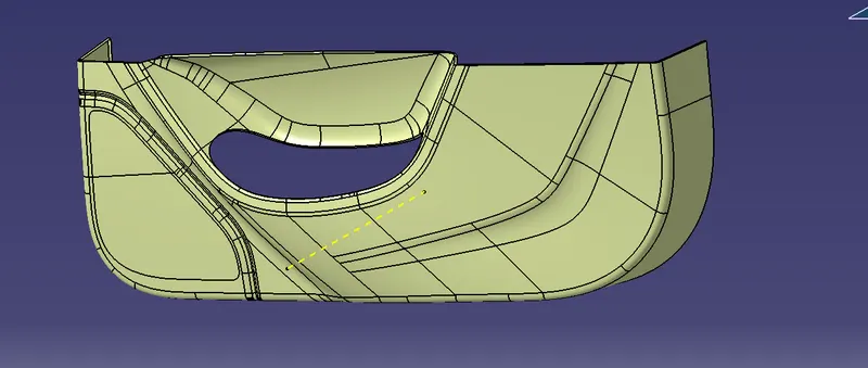
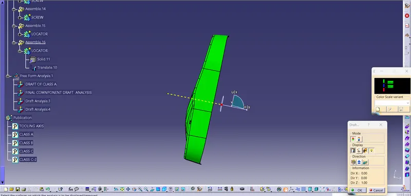
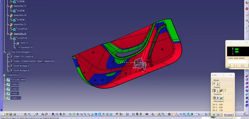
Draft Analysis :
- The part created has to be changed to material mode in display frame.
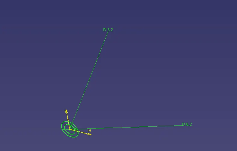
- Compass is enabled and align it along with the tooling direction.
- Lock command is then applied to fix compass along with tooling axis.
- Color codes are classified and Draft angle is applied.
- Running point analysis is used to display permissible draft angle.
Draft analysis - Final component :