Week 8 - Challenge 1 - Base Bracket Design
CHALLENGE 1 - BASE BRACKET DESIGN
AIM
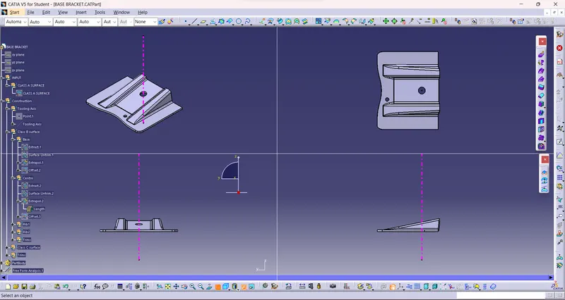
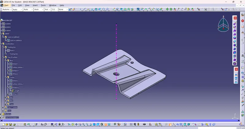
To create the Base Bracket Plastic component through the given Class-A surface. To begin with, the tooling axis for the given Class-A Surface should be created meeting the requirements of the draft angle and at the end perform the Draft analysis on the model.
1. INTRODUCTION
CLASS-A Surface
Class-A surface means visible surface. It gives the aesthetic of the component which is created by the styling team and gives to the part design engineer to create the part with all engineering aspects.
CLASS-B Surface
Class-B surface means thickness of a part it is not visible and is inside part. In other words, Class-B surface is a surface below a certain thickness from the class-A surface. This is the surface that contains engineering aspects of a model.
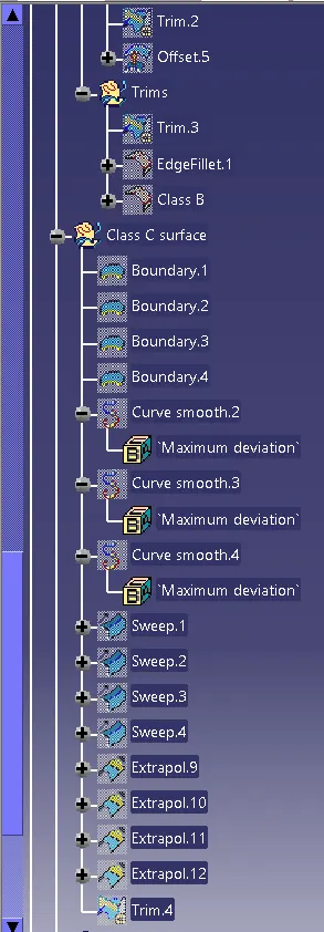
CLASS-C Surface
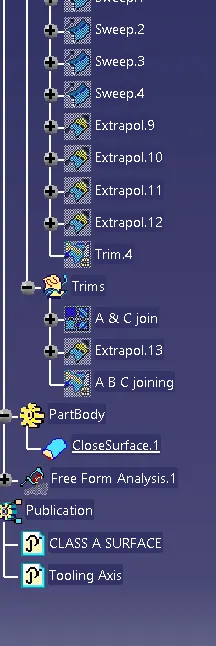
Surface that joins class-A and class-B surfaces is class-C surface. Class C is often specified for interior surfaces not readily visible, surfaces that will be covered by another part when assembled
DRAFT
When developing parts for plastic injection molding, applying draft (or a taper) to the faces of the part is critical to improving the moldability of your part. Without it, parts run the risk of poor cosmetic finishes, and may bend, break, or warp due to molding stresses caused by the plastic cooling. Equally important, an absence of draft may prevent parts from ejecting from the mold, damaging not only the parts, but possibly the mold itself—a costly and time-consuming detour.
THE DRAFT ANALYSIS AND THE TOOLING AXIS CREATION.
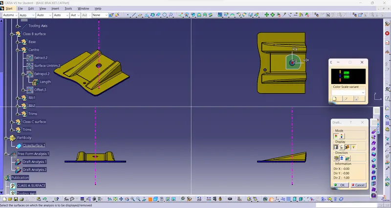
The Draft Analysis allows the user to easily analyse a part for proper draft angle. A Draft Angle describes the amount of taper for molded or cast parts perpendicular to the parting line.
Every part should clear the draft analysis test to ensure the easy manufacturability of the component.
Procedures to follow when performing the Draft analysis of the given Class-A surface are as follows
1 FOR CREATING THE TOOLING AXIS
- STEP 1: Check the connectivity of the Class A Surface
- We have been given the Class-A surface and he first thing to do is to make sure that the given surface has no gap in between them. We can check it visually and also with help of Join or boundary commands.
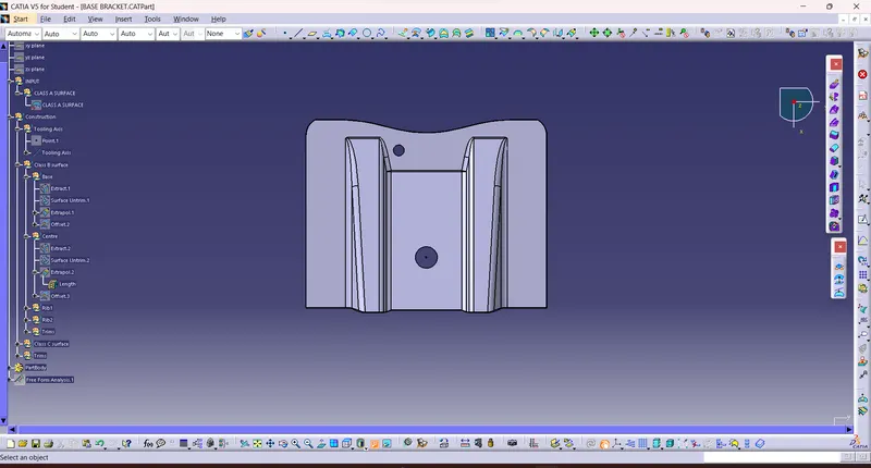
- The given surface has only three boundaries which are one outer boundary and two inner circle boundaries. So, there is no other gaps found.
- STEP 2: Find the tooling axis of the component.
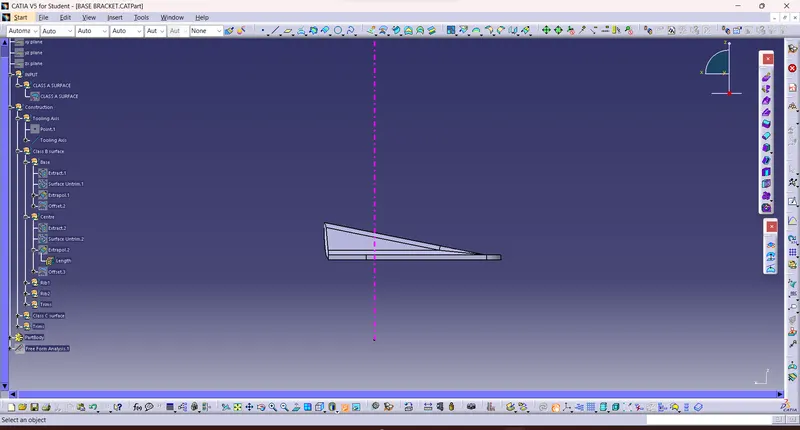
The tooling axis represents the opening and closing of mold.
A plastic product designer should consider the best tooling direction to cutdown the cost of the component very less.
We can find out the best tooling direction by cross checking all the three axis
- Here along X axis, it is possible since it would not clear the holes and which make the manufacturing expensive.
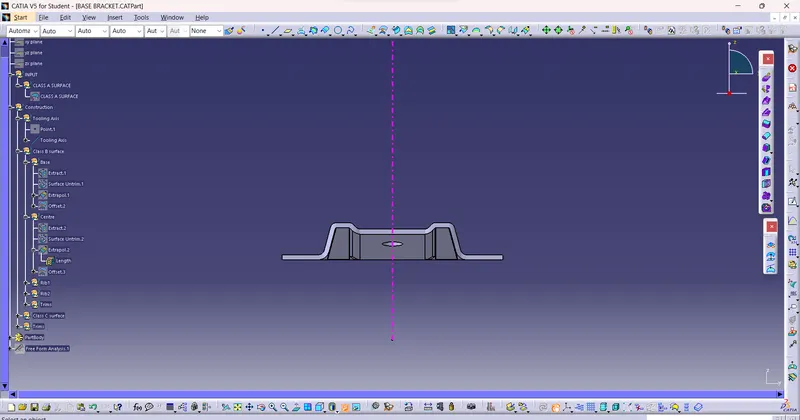
- Here Z axis is the best possible direction for tooling. It clears both holes. Hence no need to implement side cores and which leads to less cost for the molding.
-
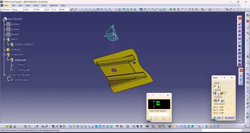
Creating the tooling axis along z direction
- We have a hole on the surface, so create boundary of the hole and create midpoint.
- Create a dummy tooling axis by creating a line on the midpoint of the circle
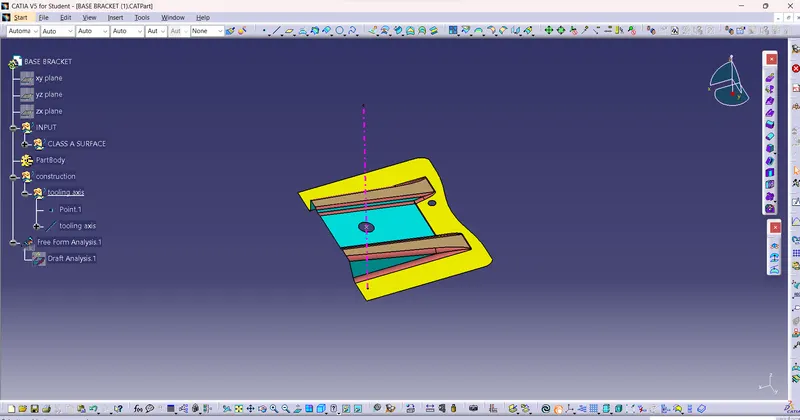
Find the tooling axis of the component.
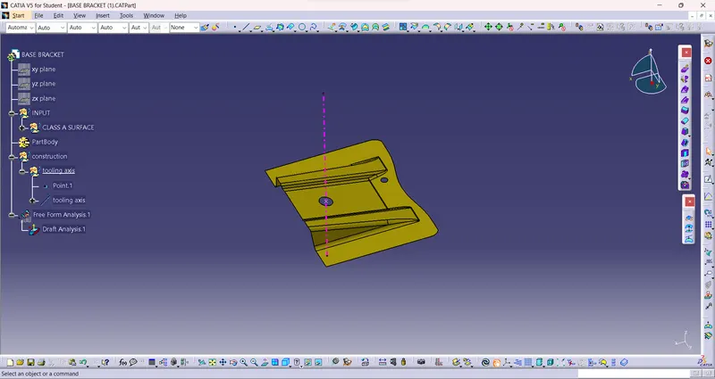
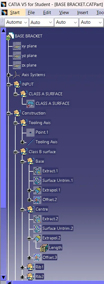
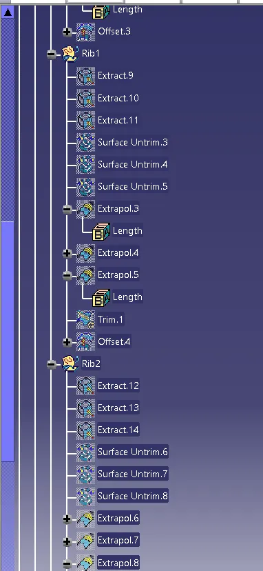
FLAT SURFACES:-
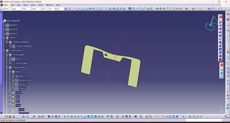
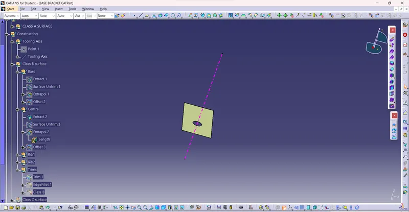
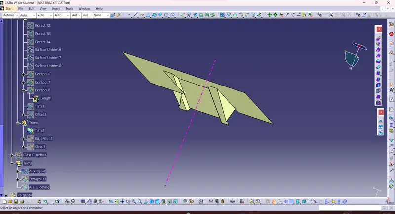
- Extract the flat surfaces
- Un-trim the surfaces.
- Extrapolate it.
- Offset it by 2.5mm
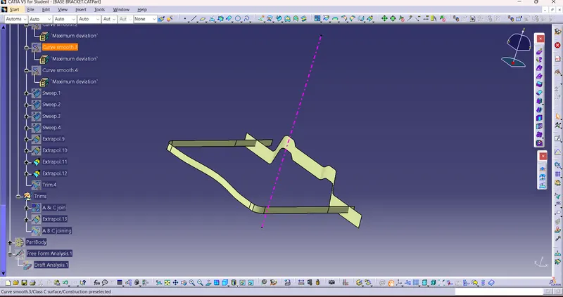
SLANT THICKNESS:-
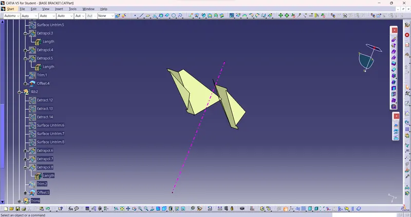
- Extract the slant surface.
- Un-trim the surface.
- Extrapolate it.
- Offset it by 2.5mm
SOLID MODEL OF A BASE BRACT: