Week 8 - Challenge 3 - Coin Holder Design
COIN HOLDER DESIGN - CHALLENGE 3
AIM
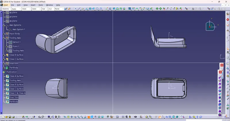
Create the Coin Holder Plastic component through the given Class-A surface. To begin with, the tooling axis for the given Class-A Surface should be created meeting the draft angle requirements and performing the draft analysis on the model at the end.
1. INTRODUCTION
A coin holder is a part that acts as a pocket for carrying coins and other small things like pen drives, keys, etc. Mostly is placed in a very easily accessible point where a driver can grab things in the con holder without any difficulties.
CLASS-A Surface
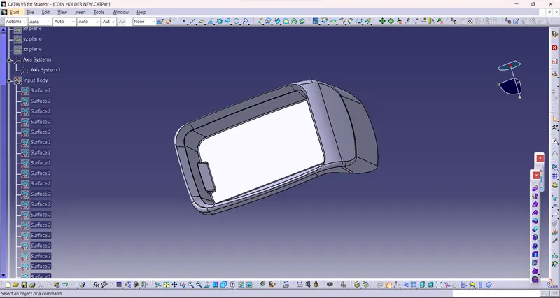
Class-A surface means visible surface. It gives the aesthetic of the component which is created by the styling team and gives to the part design engineer to create the part with all engineering aspects.
CLASS-B Surface
Class-B surface means the thickness of a part it is not visible and is inside part. In other words, the Class-B surface is a surface below a certain thickness from the class-A surface. This is the surface that contains engineering aspects of a model.
CLASS-C Surface
The surface that joins class-A and class-B surfaces are class-C surfaces. Class C is often specified for interior surfaces not readily visible, surfaces that will be covered by another part when assembled
2. OBJECTIVE
- To design coin holders as per automotive industry Standard.
- Create a tooling axis for the given CLASS-A surface.
- Create B Class and C Class
- Create a final surface model and covert it into the solid body using the close surface command in the part design workbench
- Perform draft analysis for both Class-A surface and Final part body.
2. OBJECTIVE
- To design coin holders as per automotive industry Standard.
- Create a tooling axis for the given CLASS-A surface.
- Create B Class and C Class
- Create a final surface model and covert it into the solid body using the close surface command in the part design workbench
- Perform draft analysis for both Class-A surface and Final part body.
.
3.2 Procedure for creating the tooling axis
The tooling axis represents the opening and closing of the mold core and cavity during the manufacturing of the components. A plastic product designer should consider the best tooling direction to cut down the cost of the component very less.
Method opted for creating tooling axis for the Coin Holder
- Check the best tooling direction for the given surface.
- We can find out the best tooling direction by cross-checking all three axes.
- Since it has a bin with walls, extract the base surface and create a midpoint on it.
DRAFT ANALYSIS:
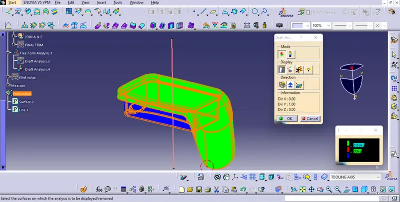
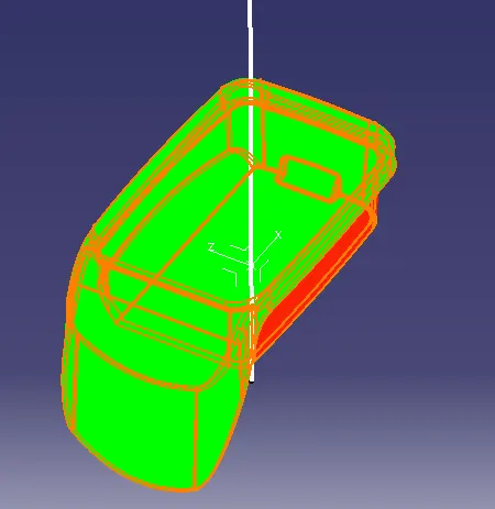
- The Drafting analysis was performed on the class-A surface by using the Feature Draft Analysis command.
- Using this command, the compass was set on the main tooling axis and the Draft angle was changed to 3 degrees.
CREATING CLASS-B SURFACE:
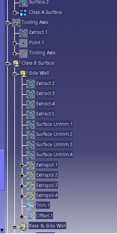
- SIDE WALLS:
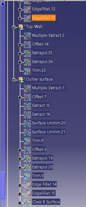
- To create a side wall by extract the class A side faces
- To untrim the extracted side walls
- To extrapolate them for make sure to pass through all together for merge
- To trim the unwanted faces from walls by trim
- To offset the walls up to 2.5 mm
- BASE:
- To create a base by extract the base from class A
- To untrim and extrapolate the base for final trim to create a B-surface
TOP WALLS:
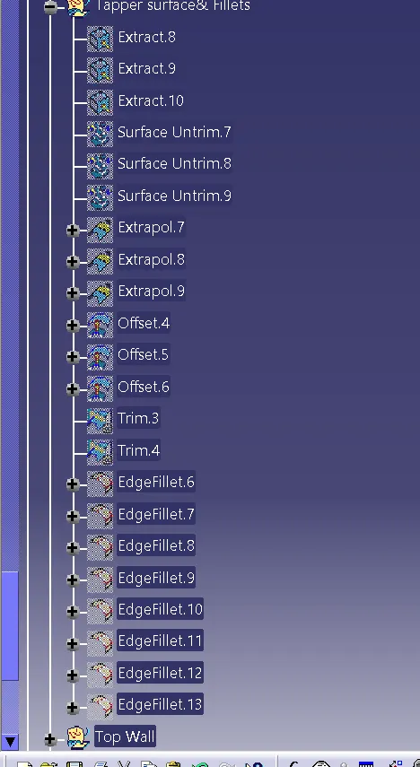
- To create a top wall by Mutiple extract the class A side faces
- To extrapolate them for up to requirement
- To offset the walls up to 2.5 mm
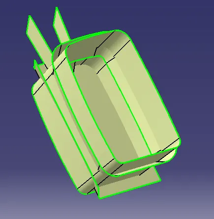
BEFORE FINAL TRIM OF CLASS B SURFACE:
AFTER INITIAL TRIM:
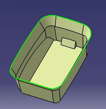
OUTER FLANGES:
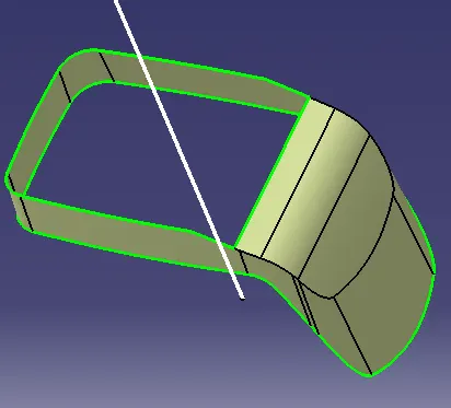
FINAL TRIM:
B-SURFACE:
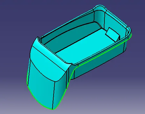
B-SURFACE
CREATING C- SURFACE:
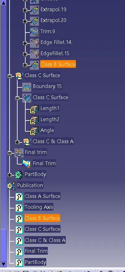
- To use multiple extract tool on the class A surface
- The extract boundaries can be sweep at 90 degrees to the reference boundaries up to required length
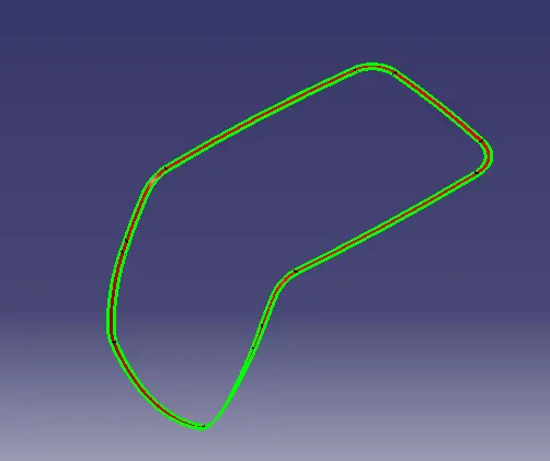
C-SURFACE