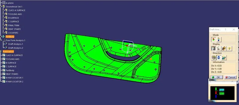
Week 9 - Project 1 - Door Trim Lower with Engineering Features
AIM
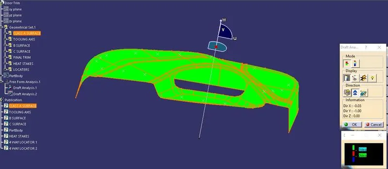
This Report aim is to perform draft analysis for the given surface by defining a tooling direction appropriate to the shape of the surface and also to create the class-B,class-C surfaces and final closed body with the help of given Class A surface of Door trim lower and to create heat stakes and 4 way loactors based on design rules.
THEORY
Class A surface:
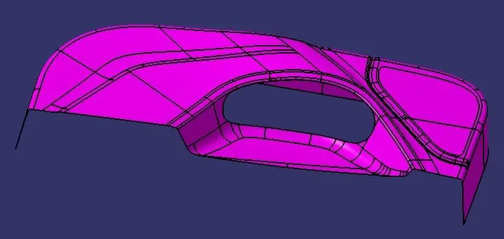
This is the styling surface which provides the aesthetic features of a component. A designer starts the design of component from a class A surface.
Given class A surface
Class B surface:
Class B surface is obtained by offsetting the class A surface by the component thickness value. This B surface contains all the engineering features of the component. So it is also called as Engineering Surface.
Class C surface:
Class C surface is created along the tooling direction of the component and it connects the class A and class B surfaces.
Tooling Axis:
Tooling axis is the direction in which the part is released from the mould.
PROCEDURE
1. Check for discontinuity:
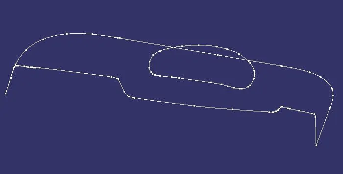
The first step any design engineer must ensure is the continuity of the surface received. In Catia this can be verified by two operations: Join, Boundary. In some cases, this can also be approved visually. Appropriate steps are to be taken if the surface has any discontinuities.
2.Defining the tooling direction
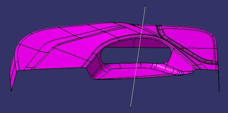
Ideal tooling direction has to be the direction in which most of the features can be easily cleared. In this case the initial tooling direction can be assumed in the direction perpendicular to the flat surfaces and the surfaces which might be difficult to clear in this direction are identified and the initial tooling direction has to be modified accordingly. But in this case the flat surfaces and the critical surfaces are perpendicular to each other. So, the initial tooling direction can be taken as the final tooling direction.
3.Creation of class-B surfaces:
B surface is created by offsetting the class A surface by 2.5mm and if there are any surfacesnot offsetted then they will be created by using multisection surface or sweep command.
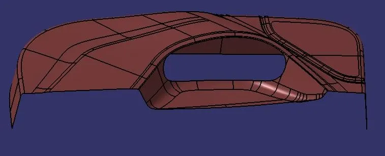
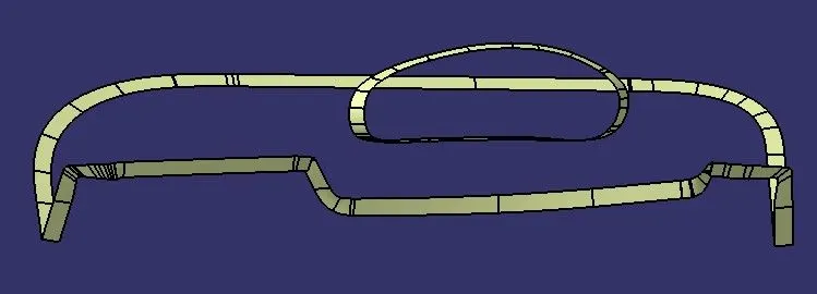
4. Creation of Class-C surface:
C surface is created by using boundary of A surface. with the help of sweep command surface is generated perpendicular to the edges of A surface.
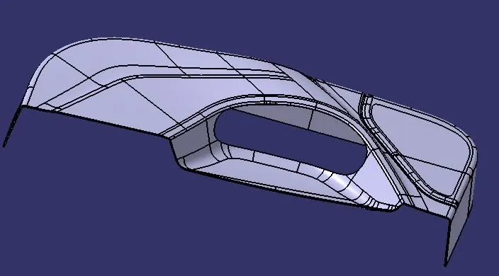
closed Body
Heat Stakes:
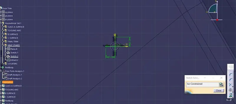
In heat staking, we use local heating and cooling to raise the temperature of plastic components and allow plastic reforming to be carried out.Then fillet is applied to the faces of the rib. As per the design rule, the fillet can be 0.25 mm.These heat stakes will enter the mating component and using a heat staking machine these heat stakes are melted and cooled. When cooled this will get hardened and the two components will stick together. Thus all degrees of freedom are arrested.
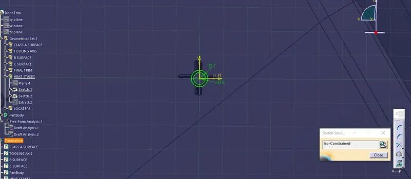
4 WAY LOCATORS:
The locators restrict all the other degrees of freedom except the translation along the direction of tooling axis Le along y-axis. For restricting that degree of freedom we will be using the heat stakes.
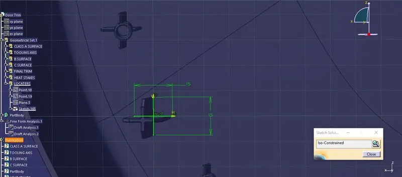
Then, the ribs are created by following the rib design ruleThe draft is applied to the sides of the ribs. As per the design rule, the ideal draft angle is 0.5 degs.
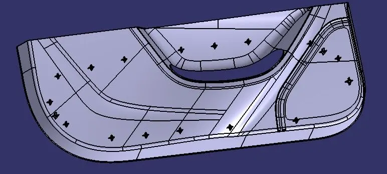
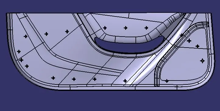
Final closed body with loactors and heat stakes
Draft analysis:
Draft analysis is an operation that is performed to know the draft angles of the surfaces concerning the tooling direction. The minimum feasible draft angle for this design is taken as 3 degrees. Generally for plastic components, a minimum draft angle that can be achieved is 0.5 degrees.
Class A surface
Final component