Week 9 - Project 1 - Door Applique Design with Engineering Features
AIM:
To Create the Base Bracket Plastic component through the given Class-A surface by using Catia V5.
OBJECTIVE:
- Create a tooling axis following the OEM standard
- Making the Surface into Solid Feature
- Create the Heat Stakes and the locators considering the design rules.
- Performing the draft analysis to the component
INTRODUCTION:
Heat staking is a pulsed – heat process to join two or more parts out of which one at least is made of plastic . The plastic is to deform the plastic material using the heat and foam at a set process time. The bond is made by partially de forming the plastic part in order to fix the other. Heat stakes makes it easily to bond metal to plastic is commonly used in high volume and low cost application such as Automotive, IT and consumer appliances.
HEAT STAKE RIVETING APPLICATIONS
Reliable joining process, especially for airbag areas
- Door panels
- Instrument panels
- Decorative covers
- Centre consoles
- Trunk trim panels
- Airbags
Design Rules for Heat staking and locators Creation:
- Degree of freedom controlled by 3-2-1 location principle
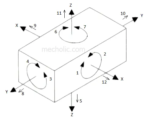
In this method, 9 degrees of freedom is controlled.
Pins A, B, C on the base plane (a plane parallel to the plane which contains X and Y axis) restrict the rotation of component about X axis and Y axis. It also limit the downward movement of component along z axis. Ie. 1,2,3,4 and 5 degrees of freedom is restricted.
Pins D, E is in plane parallel to the plane containing X and Z axes. It prevents the rotation of component about Z axis (6, 7 degree of freedom) and the movement of the body in along Y axis towards one direction (8 degree of freedom).
- Basic Rules for Location
- Choosing Locating Surfaces
The last pin F is in a plane parallel to plane contains Y and Z axes. It restricts the movement component along X axis in one direction.
Three remaining degree of freedom 10, 11, 12 is unrestricted. It facilitates the loading of the component in the fixture. This three degree of freedom may restrict after loading of component by using clamping devices.
METHODOLGY:
- Creating the Tooling Axis
The tooling direction is used to find the direction in which the part is removed from the core and cavity. The draft angle should be positive to the tooling axis to manufacture the component easily. The step by step procedure of creating the tooling axis is given below.
Step: 1
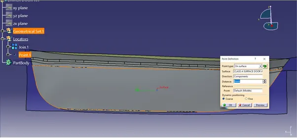
Creating the point on surfaces respectively also extract the surface of the component.
Step: 2
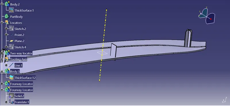
Now creating the line perpendicular to the point through y direction of the surface as shown below.
- Creating the Solid Features of Door Applique and Attachment surface:
Step: 1
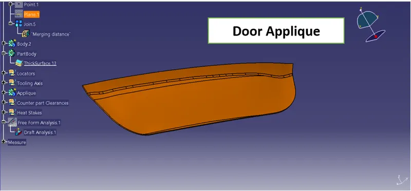
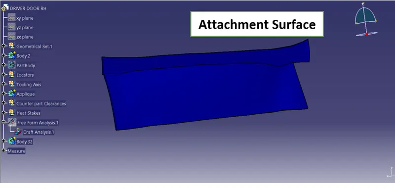
Creating the solid feature by extracting the class A surface, by each surfaces separately, thickened about 2 mm using insert body option in part design as shown below.
Step: 2
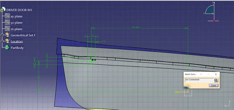
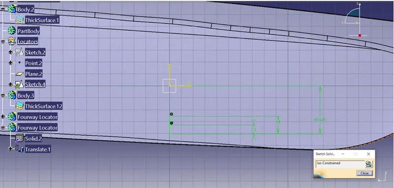
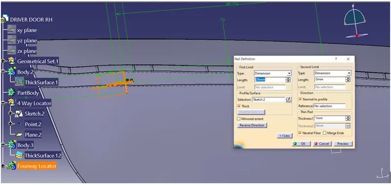
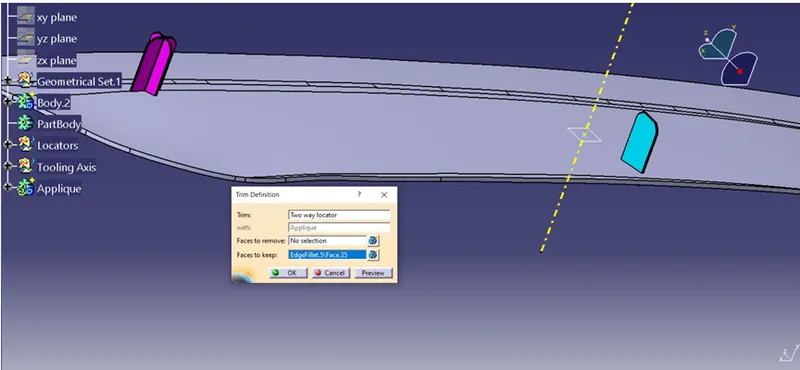
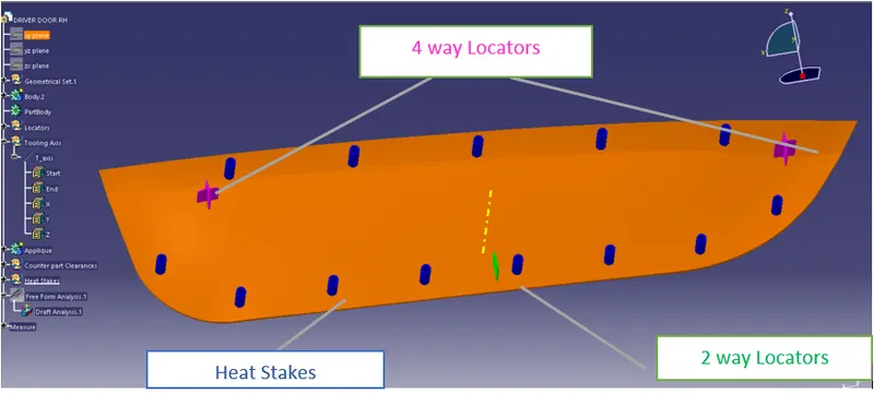
Creating the sketch of 4 way and 2 way locater and its is extruded by thickening the component for 1mm respectively has shown below.
Step: 3
Once we extrude the locator’s it has been drafted for angle 0.5 making edges chamfered for 3mm – 45 deg and filleted the edges for radius 0.3 mm as shown below.
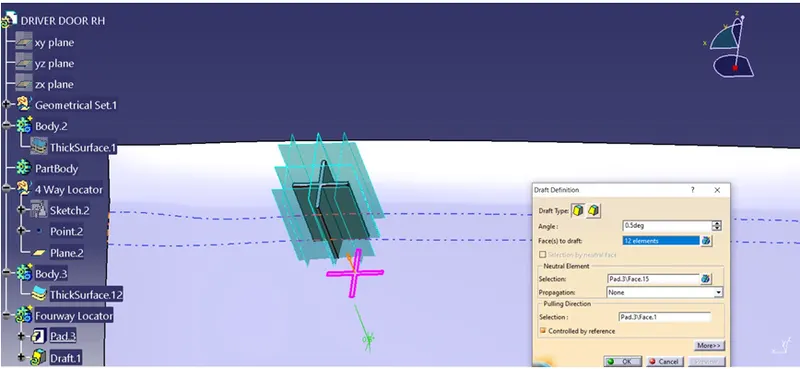
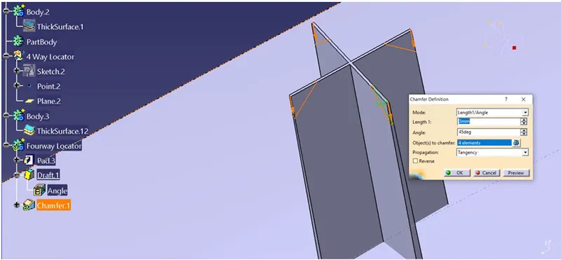
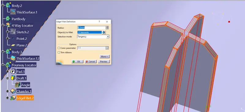
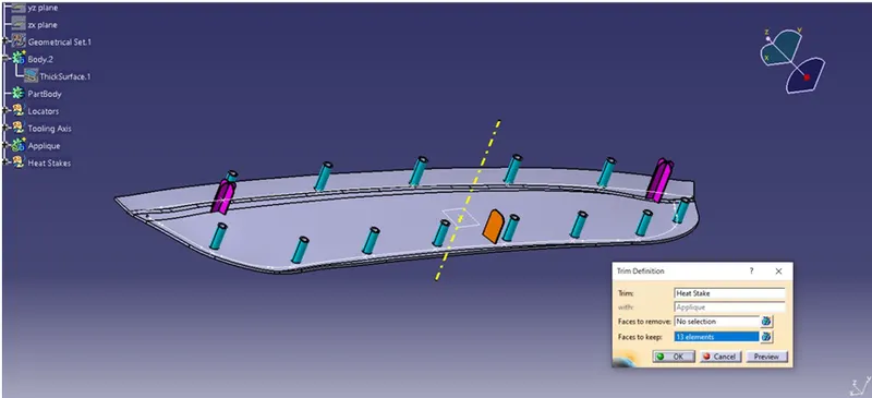
By the same way created the heat stake and 2 way loacator by following those procedure.
Step: 4
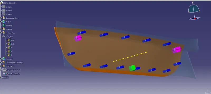
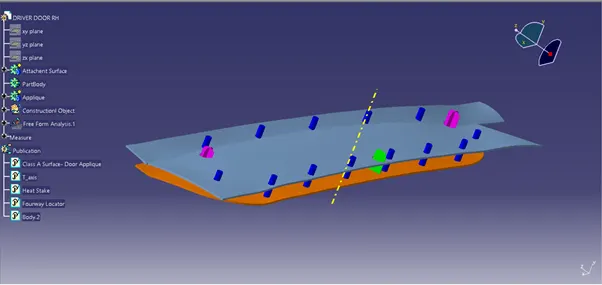
Once the every thing created in the doorapplique, now it is ready to surface attachment. First the locators and Heat stake are assembled with door applique, as shown below.
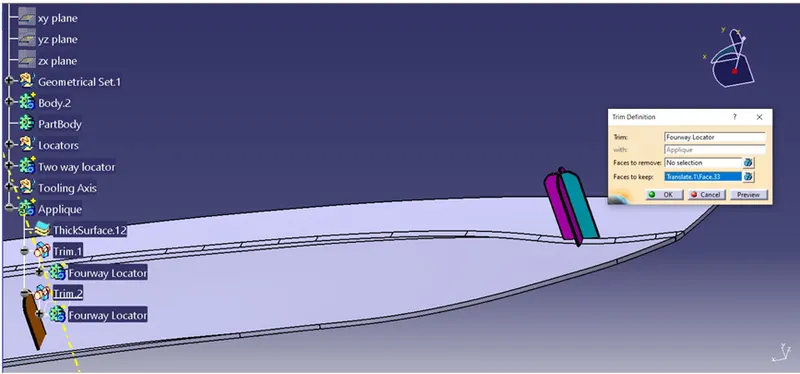
Step: 5
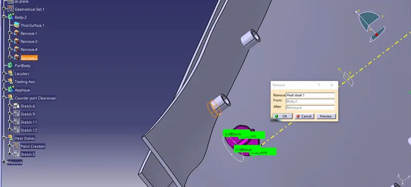
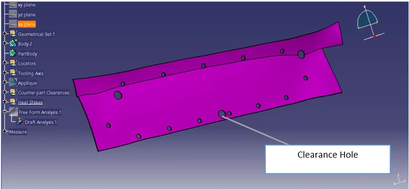
Final attachent is made by creating the hole in attachment surface for the draft angle 0.5 deg with clearance value as shown below.
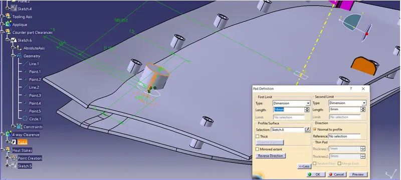
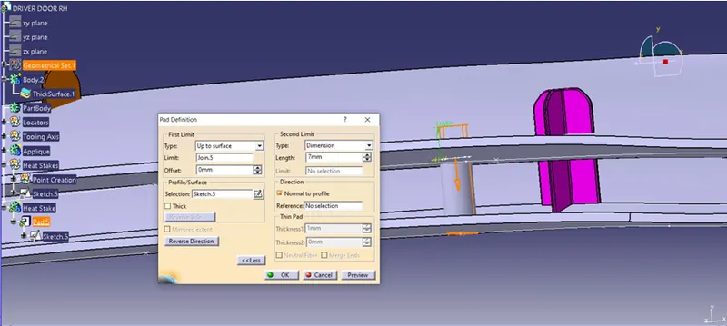
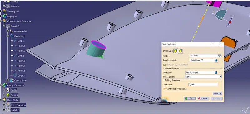
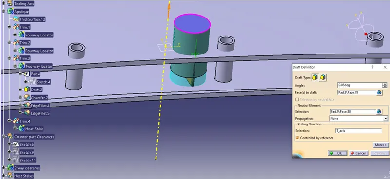
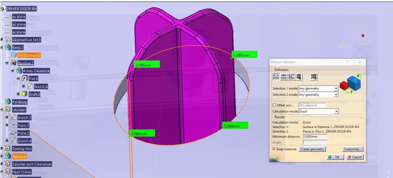
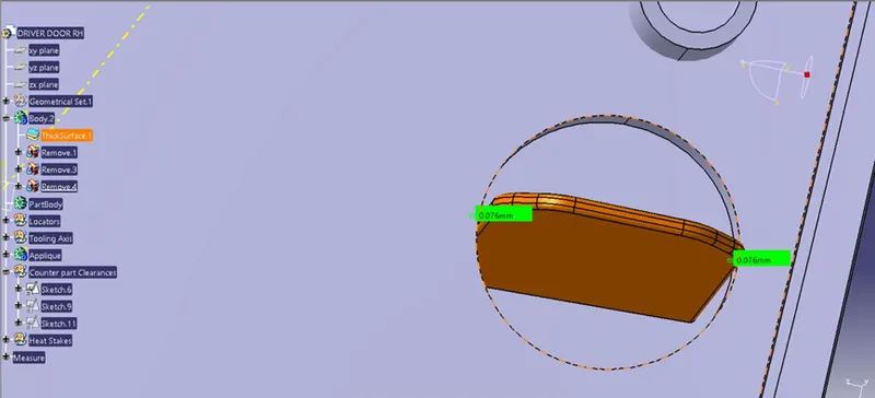
Once the drafting done, it is removed the from attachment surface and checked the clearance gap between locators and cutout as shown below.
Step: 6
Finally we achieved the mating the door applique in the surface attachment by using the 4 and 2 way loactors and heat stakes, its displayed for the reference.
- Performing Draft Analysis:
The Draft Analysis command enables you to detect if the part you drafted will be easily removed. This type of analysis is performed based on colour ranges identifying zones on the analysed component where the deviation from the draft direction at any point, corresponds to specified values. This rule of thumb applies to parts with mold depths of up to 2 inches. At this size, draft as low as 1½ degrees will allow for an easy, non-damaging release from the mold when the expected shrinkage of the thermoplastic material occurs.
It’s also important to remember that draft angles are just one component of an effectively designed injection molded piece. Design for manufacture is one of the easiest ways to improve the quality and efficiency of your injection molding process, and it never hurts to stay up to speed on all injection molding best practices.
- Draft Analysis for Door Applique:
Step: 1
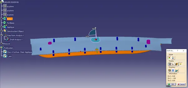
First we have to set the compass on the main tooling axis to get the direction of core and part moves along as shown below.
Step: 2
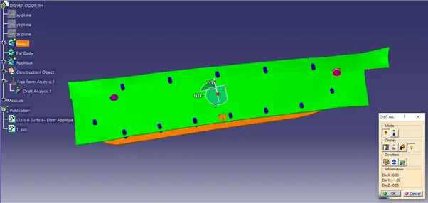
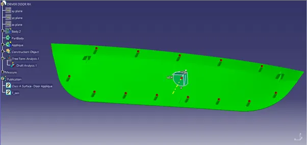
Once compass is locked in the axis, directly click on the surface it will appear quality of draft surface whether, it is pass or failed. Here the draft angle is given as 0.5 degree. Hence we achieved green colour on top surface. Hence it accepts the draft angle for the surface, so we build good quality component.
Step: 3
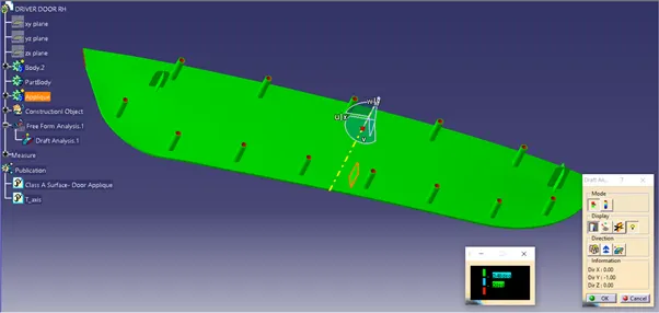
Now we check colour variant scale to ensure the maximum and minimum area draft angle is achieved by displaying by green, red and blue colour respectively. If the surface appears red in colour while analysing it is not accepted.
Step: 4
We can check the angle of draft given to surface by using draft tool analysis just point the over the surface where we have check angle of given draft to the component as shown below.
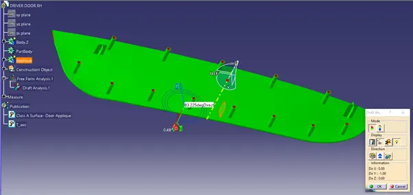
Screenshot views of coin holder with draft analysis:
Front View:
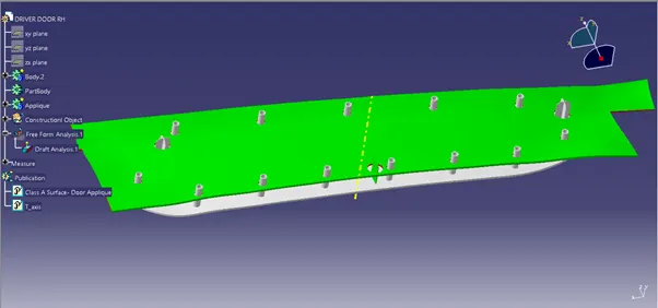
Top View:
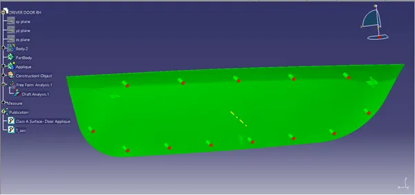
Isometric View:
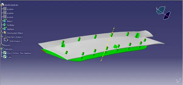
Publication:
Conclusion:
Creation of the Heat stake and Locators has been successful done by guidance of design rule. It has been converted from surface into solid body. The tooling axis has been created according the OEM standard. Drafting Analysis has been performed and results has been updated in step by step methodology. Hence the Door Appilque has finally locked with attachment surface with the help of Locators and Heat Stake with attach by mating component by melting.