Week 9 - Project 1 - Door Applique Design with Engineering Features
Aim: Creating the Door Applique and Door Attachment component through the given Class-A surface, and add Locators and heat stakes. To perform Draft analysis on the final component.
Description:
Tooling Axis Creation:
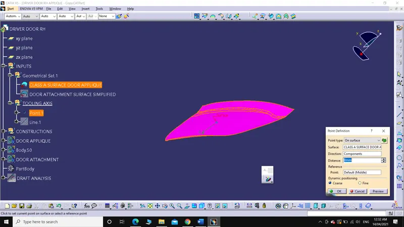
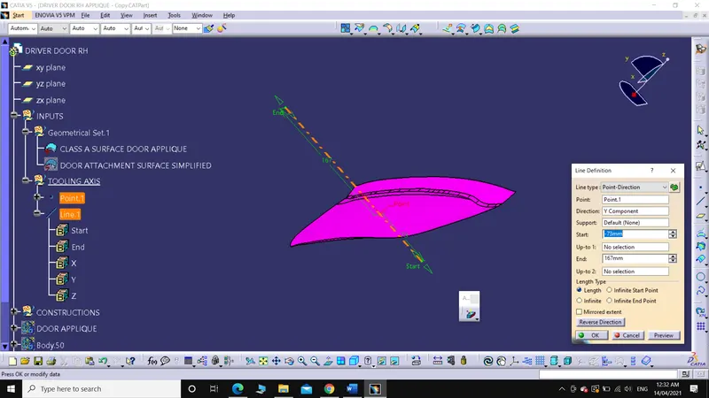
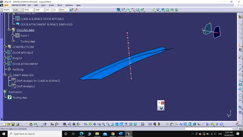
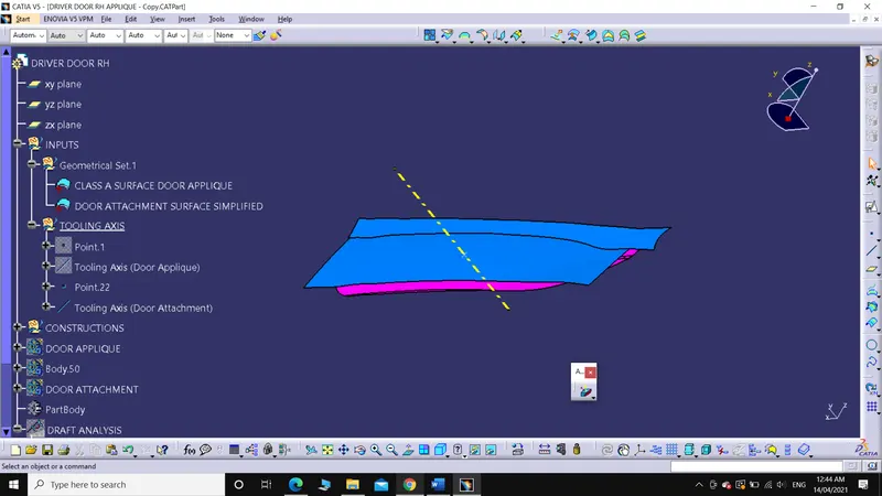
Since both Door Applique and Door Attachment are not having more complex shape, So they can be ejected consider the same tooling axis.
a. Door Applique:
Create a point on the Class A-Surface and draw a line perpendicular to surface (because this surface does not have any complex shape for which we need to use other method for creating tooling axis).
b. Door Attachment Surface:
Steps involved in creation of Class B-SURFACE:
1. Extract the surfaces (other than the filleted surfaces), untrim and extrapolate the surface.

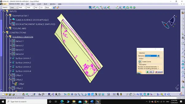
Offset all the untrimmed surfaces to a distance of 2.5mm (Thickness).
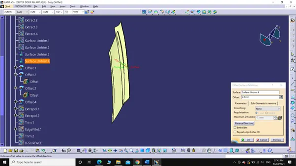
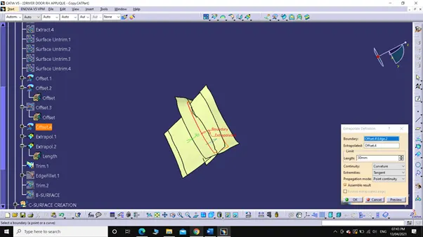
2. Trim the intersecting surfaces in order to get the required shape.
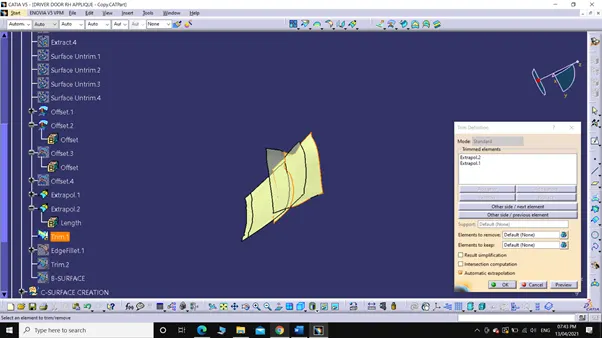
Fillet to be applied on the sharp edge.
Fillet radius for the surface = Fillet radius of the surface on Class A-Surface – Thickness of the component.
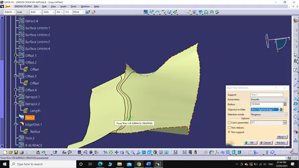
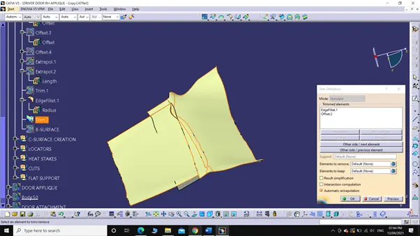
Finally, by trimming the unwanted surfaces we get Class B-Surface.
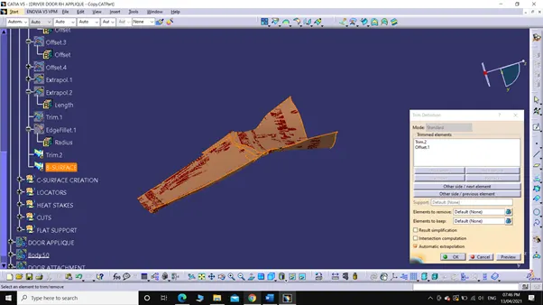
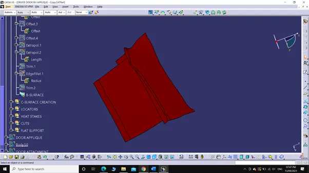
CLASS B-SURFACE.
Steps involved in creation of Class C-Surface:
1. Extract the outer boundary (of Class A-Surface), change it to smooth curve (to avoid creation of patches).
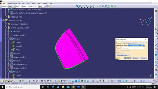
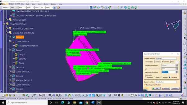
This is to be follwed until every edge of the Class A-Surface is not extracted.
Point continuity could have been used, but due to the irregular shape of the edges the SWEEP operation won’t execute the output.
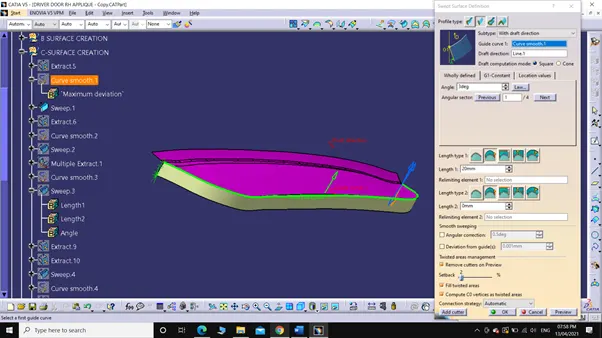
2. Using "sweep with reference surface" a surface at 30 angles has been created as shown in below pictures.
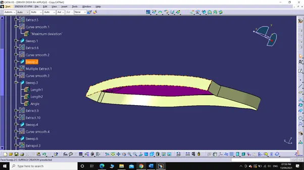
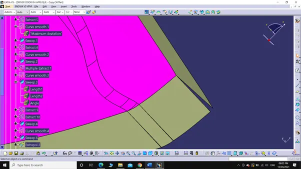
As you can see in above snap that after every edge is swept there are gaps between the surface, to have proper and closed surface I have extrapolate and trimmed the extra surfaces.
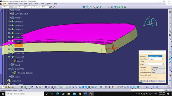
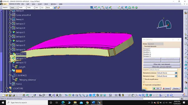
3. Join Class A-Surface with the swept surface and Class C-Surface is created.
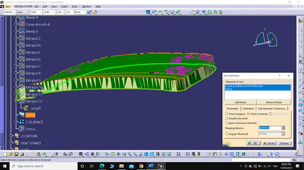
CLASS C-SURFACE.
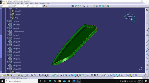
Steps involved in creation of Solid component:
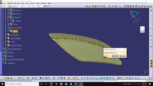
1. Changing the window from "Generative shape design" to "Part design" and choose "Close Surface" from "Surface based features" toolbar.
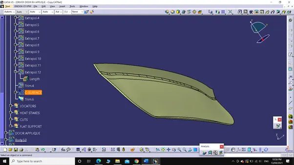
2. Selecting Class C-Surface as "Object to Close" and solid part is created.
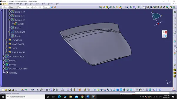
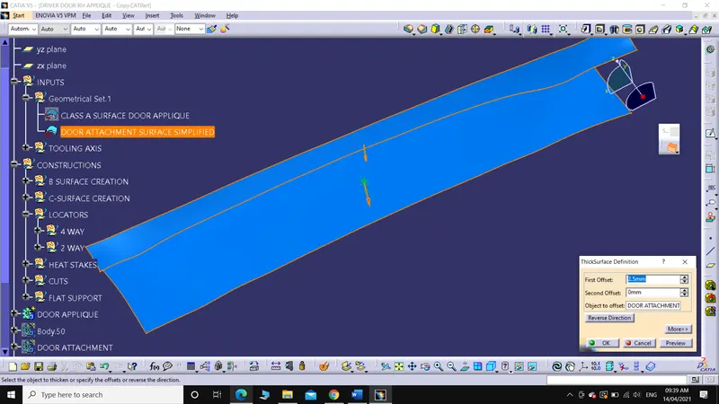
Door Attachment is converted to solid by applying the thicken option, because it is metal component.
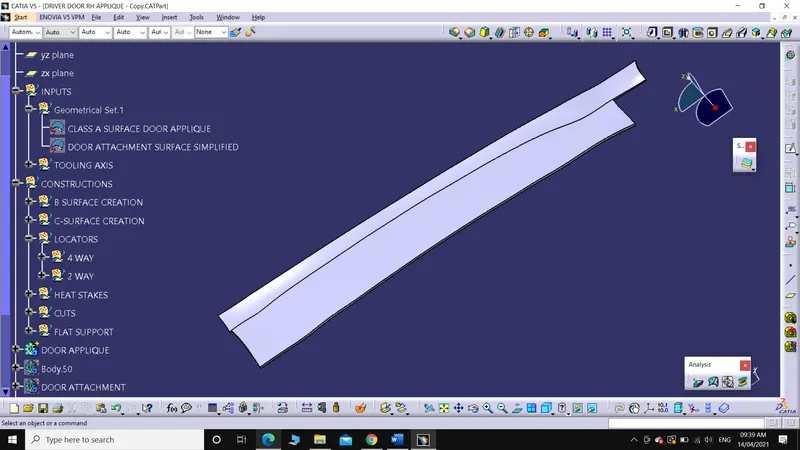
Locators Creation:
In this project two 4-way and one 2-way locators are used for arresting the freedom of degree.
For 4-way and 2-way locators:
1. Slect a plane and define the Positioning sketch.
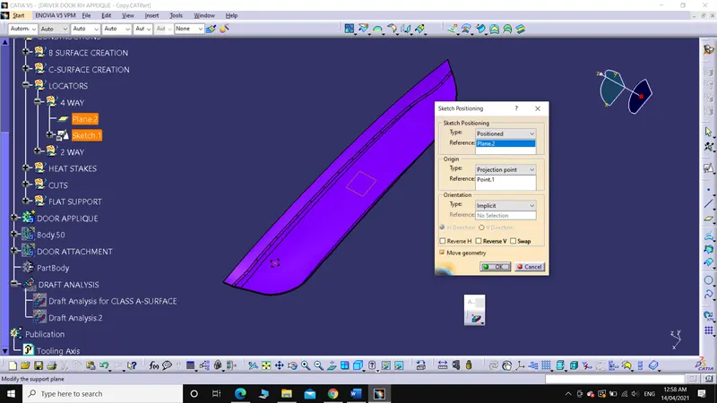
2. Draw the profile for 4-way and 2-way locators.
For creating profiles of locators the guidelines of RIBS are utilized.
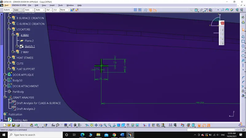
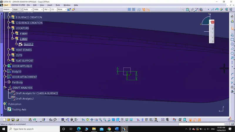
3. Pad the profiles and give draft wherever required.
Chamfer of 2 X 45 degrees is given on top corners.
Fillet of radius 0.25mm to every sharp edge is given.
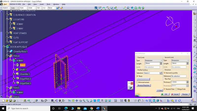
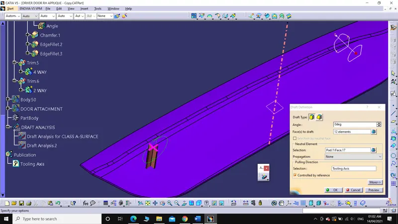
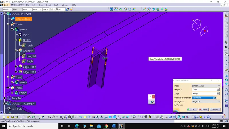
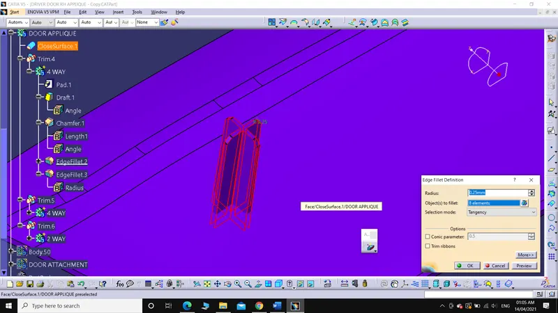
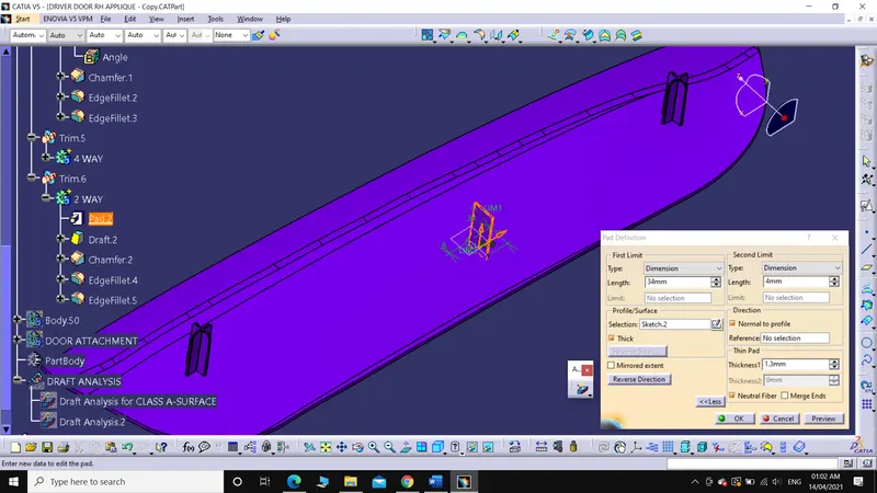
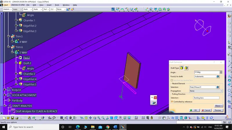
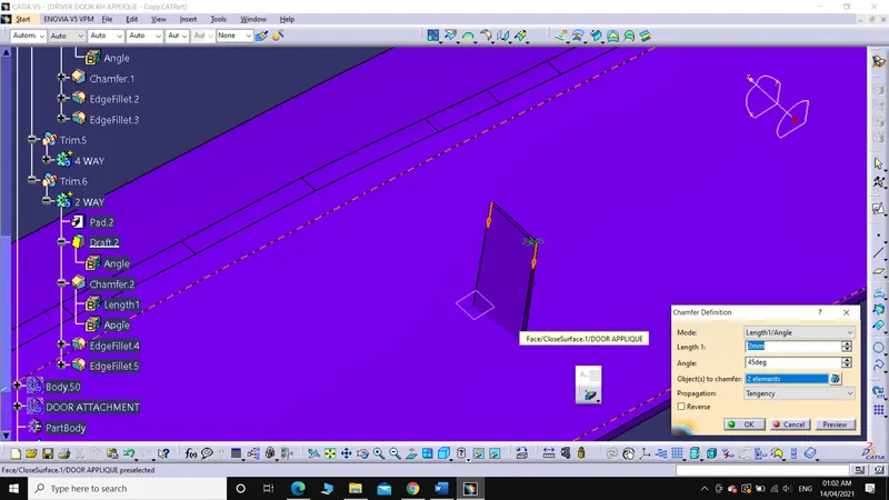
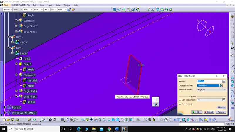
Another 4-way fillet is created using the 'Paste special' option, and is then translated.
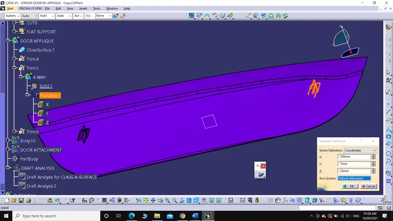
DOOR APPLIQUE WITH LOCATORS:
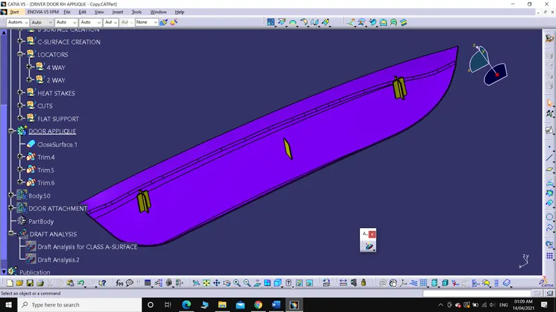
Heat Stakes Creation:
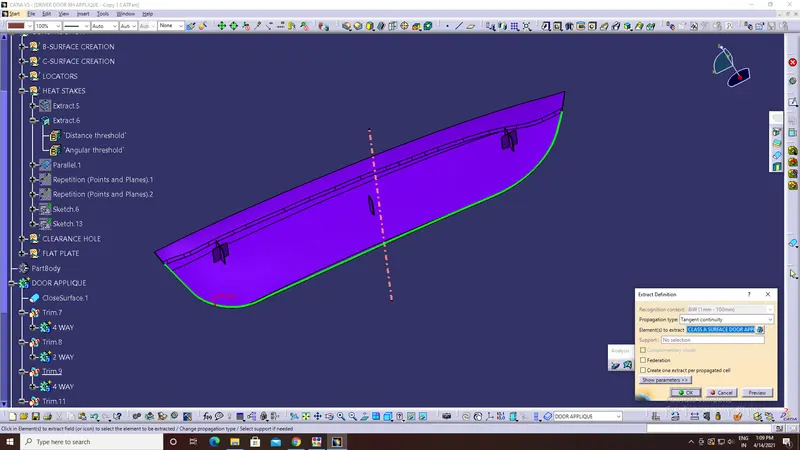
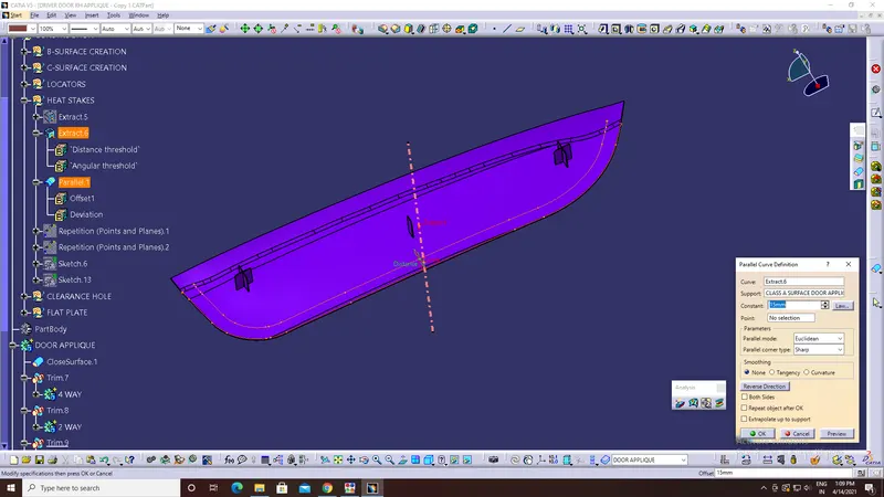
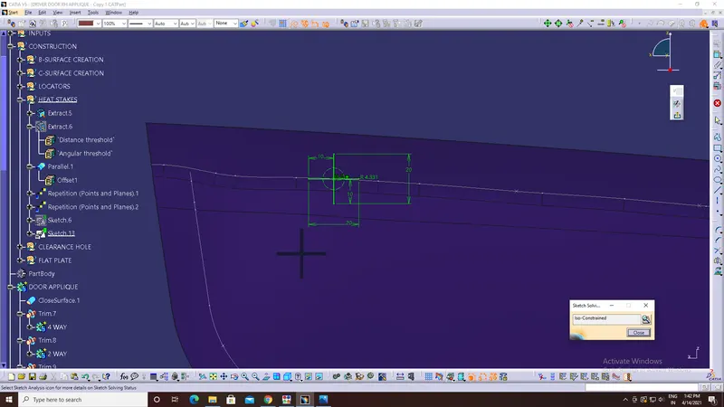
1. Extract the edge and offset it to certain distance and create points (as per requirement) with minimum of 50mm spacing between each points.
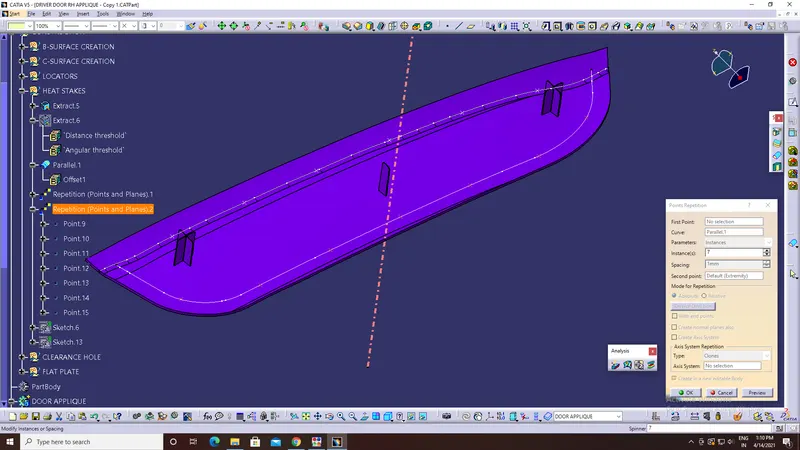
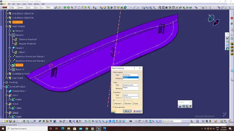
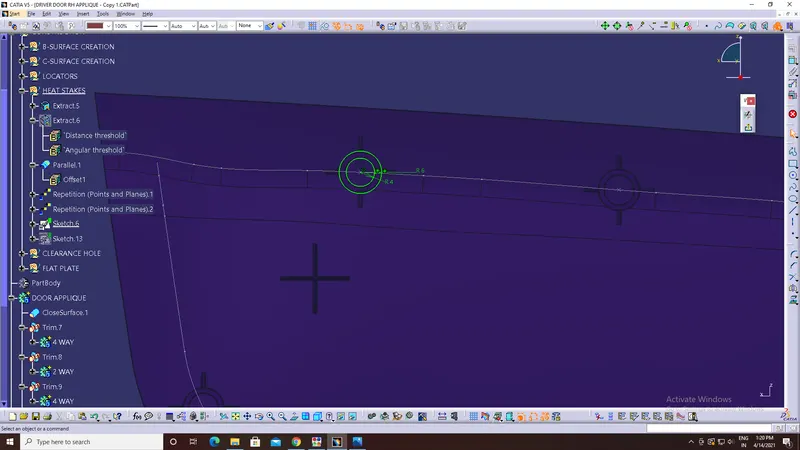
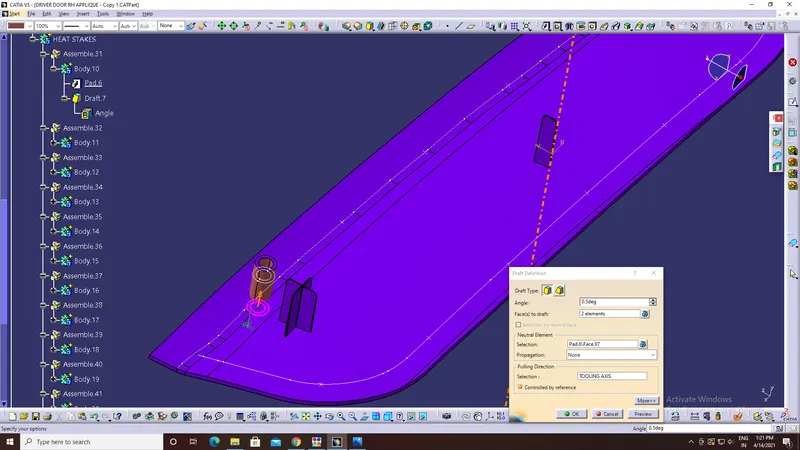
2. Define a positiong sketch and draw the profile for the Heat stake (thickness = 1.25mm) on any one point. Then' pad the profile and give the draft (draft angle = 3 degrees).
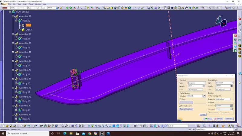
3. Using 'Paste special' option create clones (which are linked with the parent profile) as per requirement. Then, translate each one onto the points created.
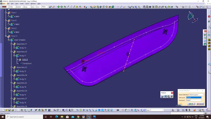
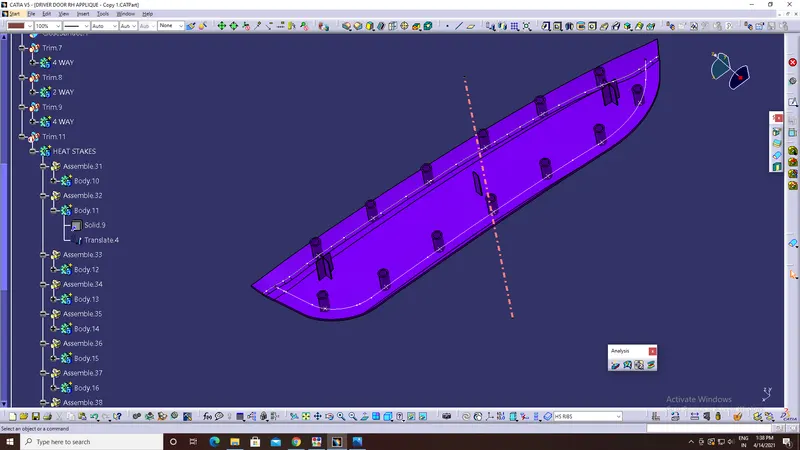
To provide strength to the Heat stakes Ribs are created around the heat stakes.
While creating these ribs, the guidelines of ribs are followed.
Profile of rib is created and is padded to certain length and using 'Union trim' the portion intersecting the Heat stakes are trimmed.
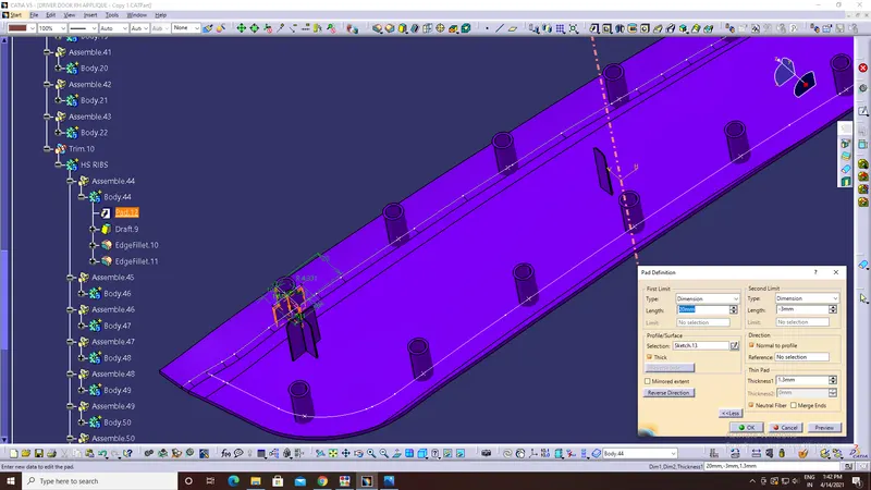
Draft of 0.5 degrees & Edge fillet of radius 0.25mm is given to the above created ribs.
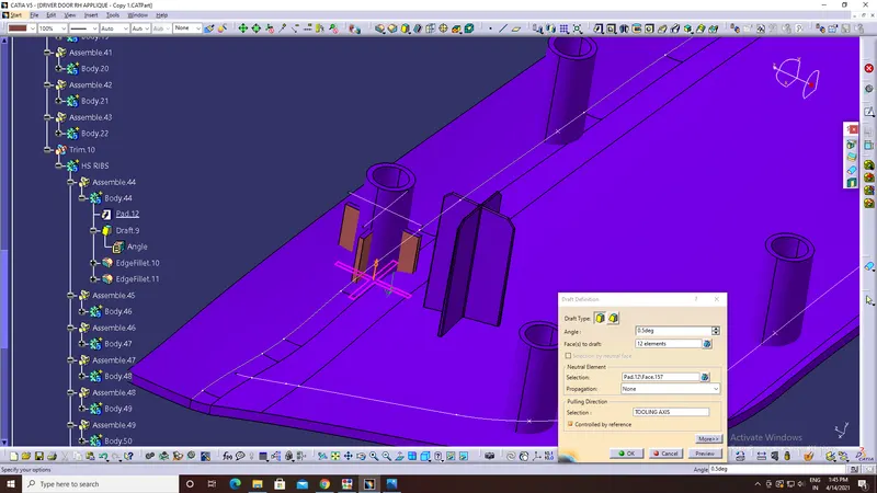
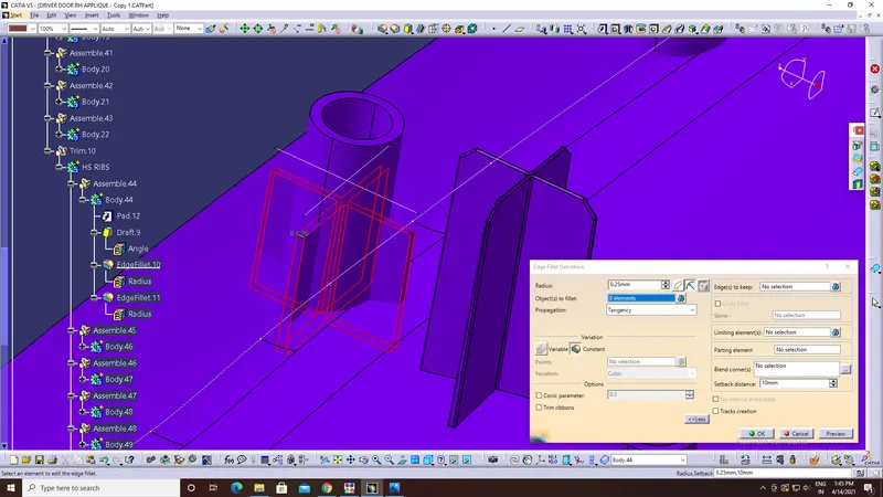
Using 'Paste special' option create clones (which are linked with the parent profile) as per requirement. Then, translate each one onto the points created. Then, using 'Assemble' Boolean operation assemble to the door applique.
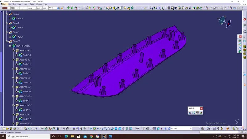
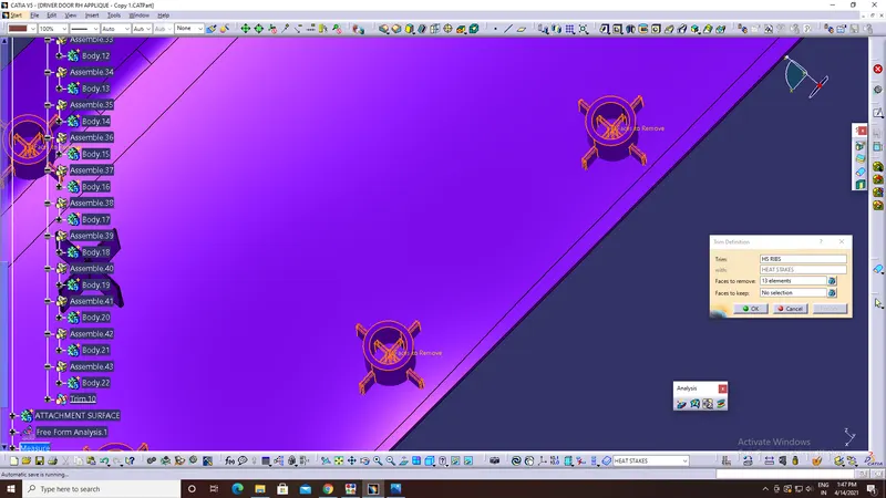
Finally, Union trim it to Door Applique component.
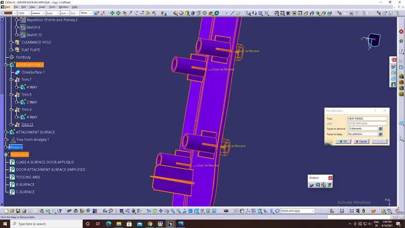
Cleareance holes for Locators and Heat stakes on the Door Attachment component:
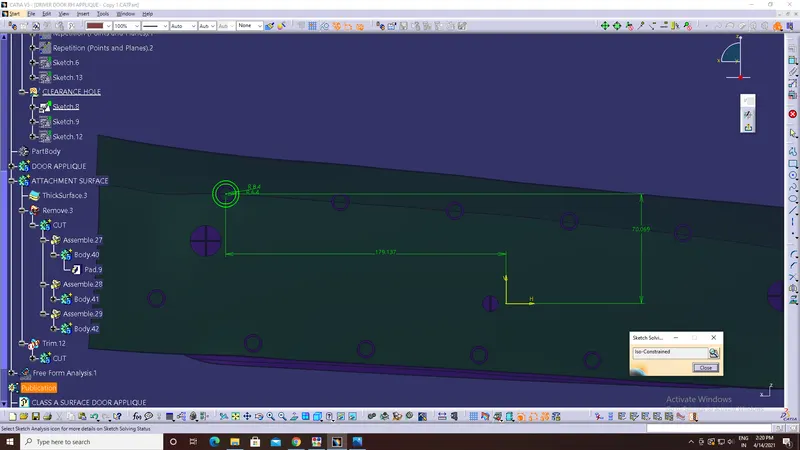
1. Position sketch is defined and a profile with cleareance about 0.01mm is drawn around all the locators.
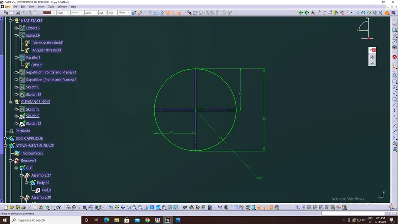
2. Pad the profile and remove from Door attachment using 'Remove' Boolean operation.
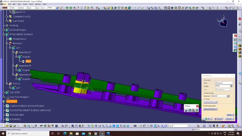
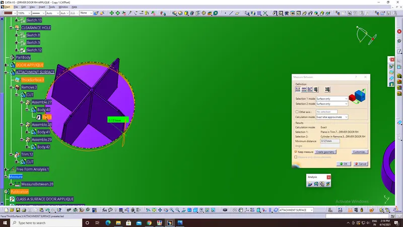
3. Create profile with cleareance about 0.05mm around Parent Heat stake and follow same steps.
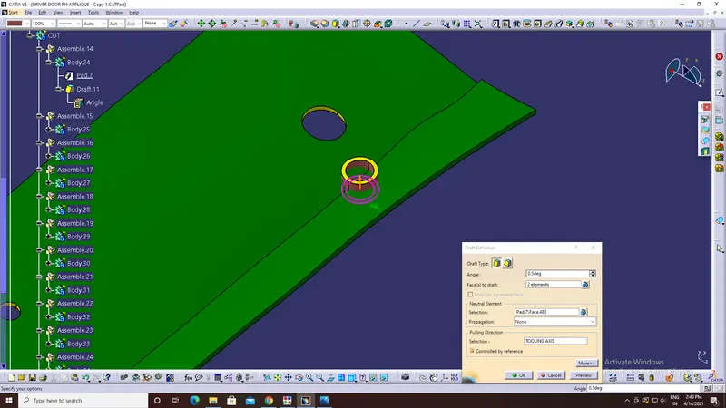
For Heat staking machine to set properly on the Heat stakes a flat surface is required, So that the staking is uniform on the surface. For that reason I have created a profile and padded it about 2mm above the Door attachment surface.
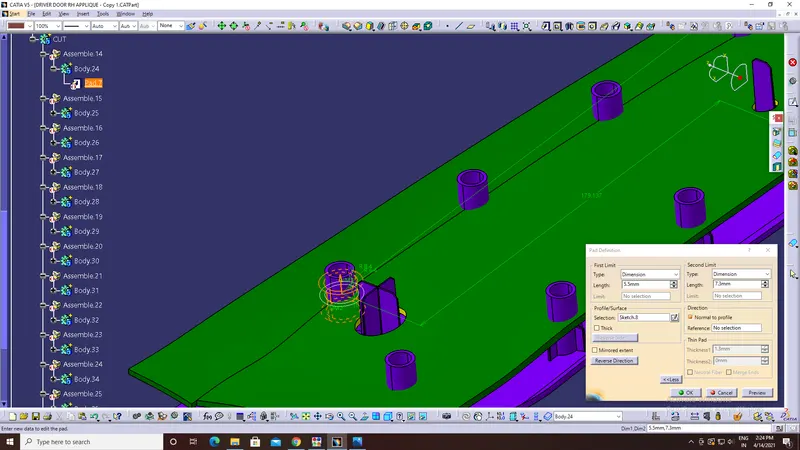
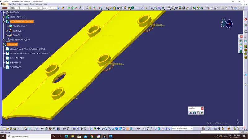
Draft of 0.5 degrees is provided.
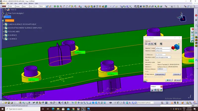
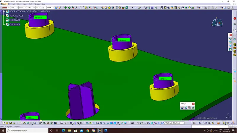
Note: The Heat stake top surface should be at a height of minimum 5mm above the falt surface created.
Steps involved in Draft analysis on:
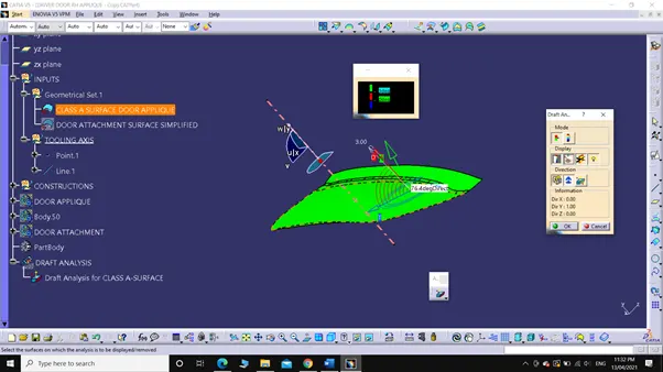
a. Class A-Surface of Door Applique:
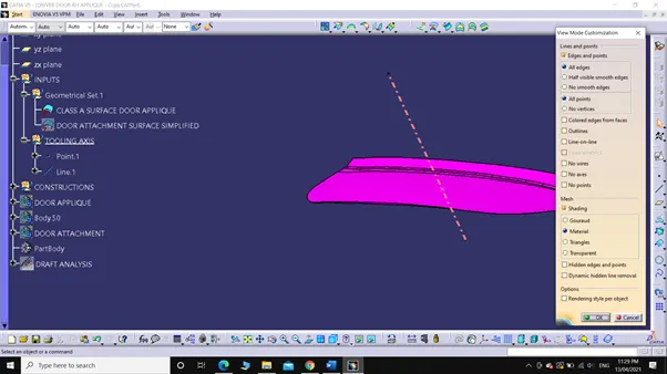
1. Select 'Customize view parameters' from the 'View mode' and choose 'Materials'.
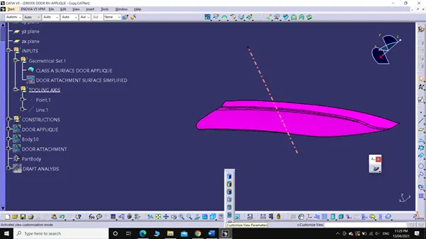
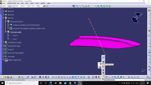
2. Select 'Feature Draft Analysis' from the 'Analysis toolbar'.
3. Now, holding the red-dot, which is on the compass (present on Top-right corner of the window) align with the Tooling axis and lock it.
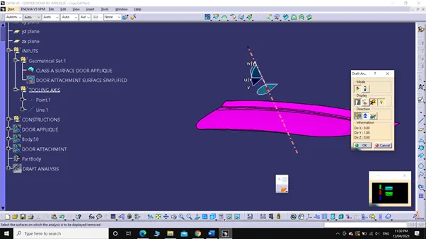
4. Set the Minimum draft angle (3 degree for plastic components) in 'Draft Analysis' dialog box (Which has different colour bars). Choose Class A-Surface of Door Applique as element in 'Draft Analysis' dialog box or Just click on the surface.
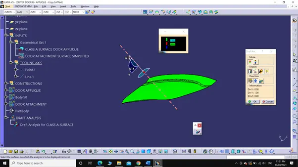
5. After selecting if the colour changes to,
Green, then the draft of the Part has minimum draft angle of 3 degree.
Red, then the draft angle of the part lies between 0-3 degree.
Blue, then the draft angle of the part is less than 0 degree.
6. By choosing 'Analyse under running point' from 'Analysis toolbar' we can check the draft angle at any point on the surface just by moving the pin.
b. Class A-Surface of Door Attachment:
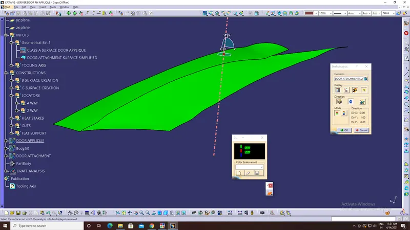
Same steps should be followed as done for Door Applique, but only the tooling axis and the surface changes.
c. Solid component of Door Applique:
Same steps should be followed as done for Door Applique, but elements to select changes and draft angle of 0.5 is considered.
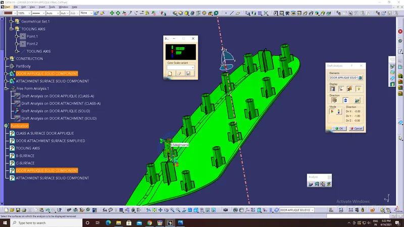
Green, then the draft of the Part has minimum draft angle of 0.5 degree.
Red, then the draft angle of the part lies between 0-0.5 degree.
Blue, then the draft angle of the part is less than 0 degree.
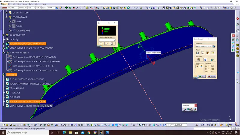
d. Solid component of Door Attachment:
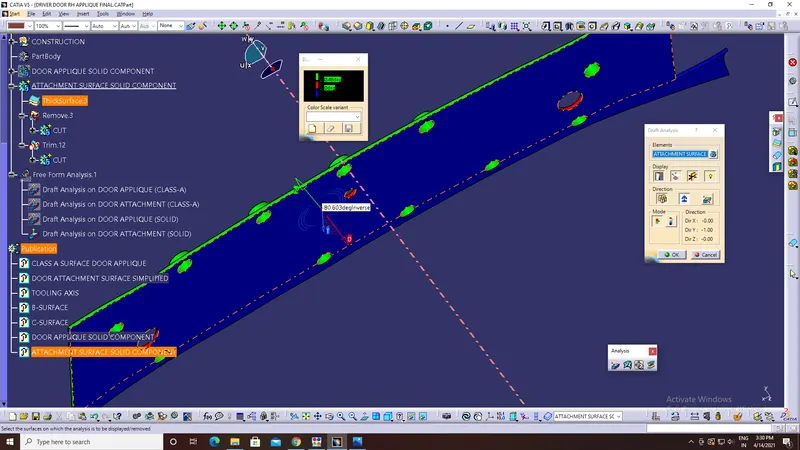
Same steps should be followed as done for Door Applique, but elements to select changes and draft angle of 0.5 is considered.
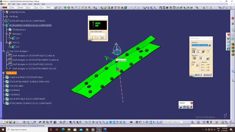
Green, then the draft of the Part has minimum draft angle of 0.5 degree.
Red, then the draft angle of the part lies between 0-0.5 degree.
Blue, then the draft angle of the part is less than 0 degree.
Screenshot of components in different orientation:
a. Door Applique:
1.Isometric View:
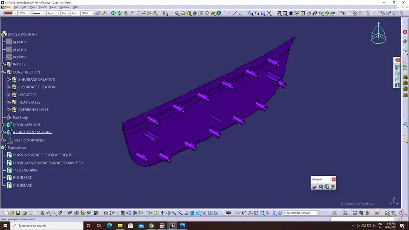
2. Front View:
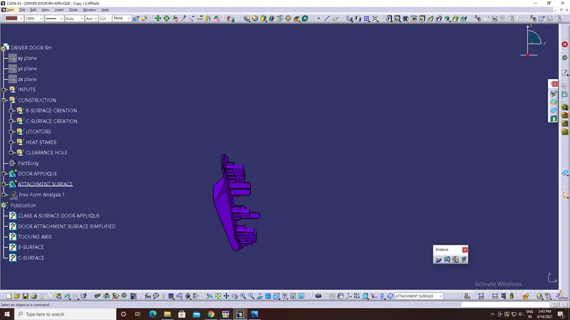
3. Right View:
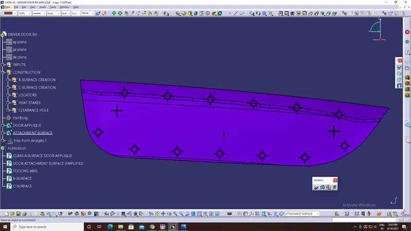
4. Left View:
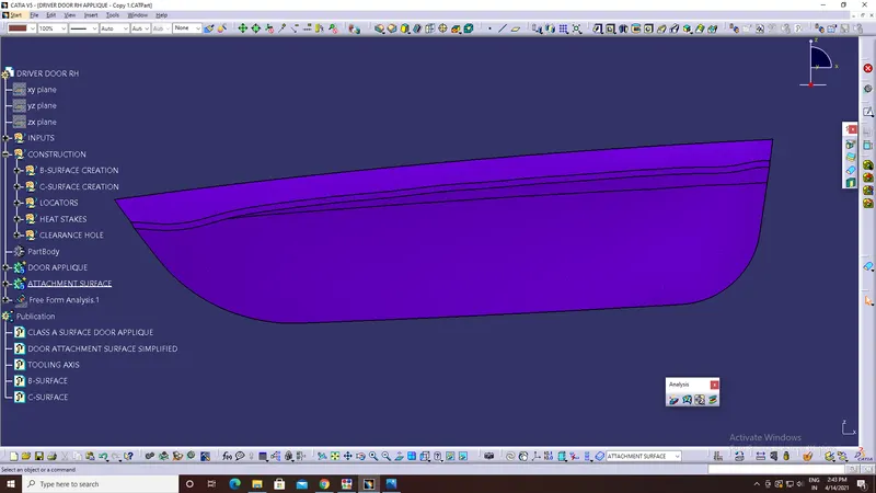
5. Top View:
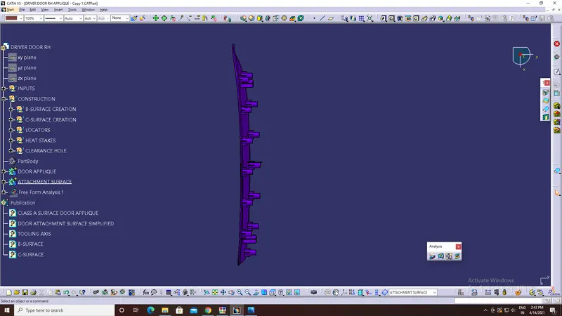
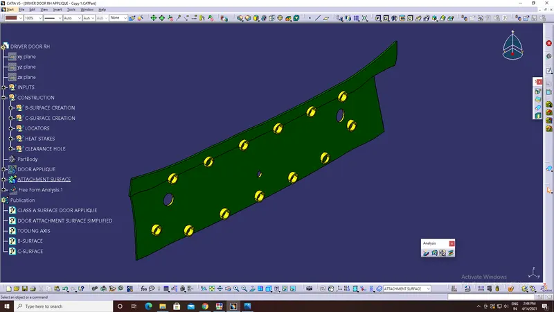
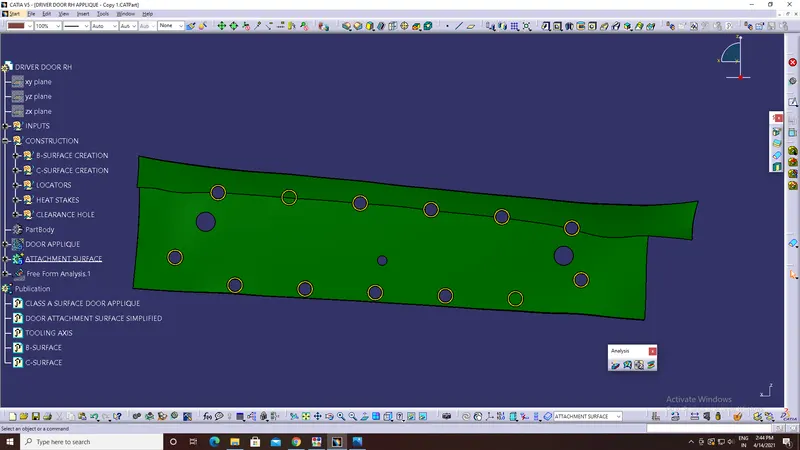
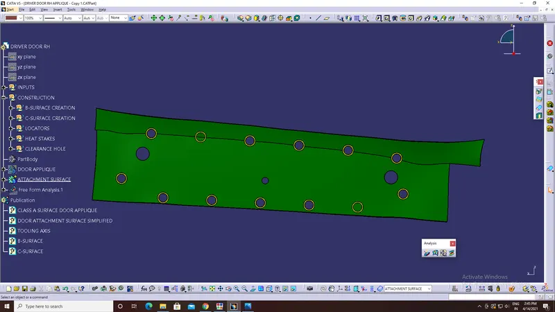
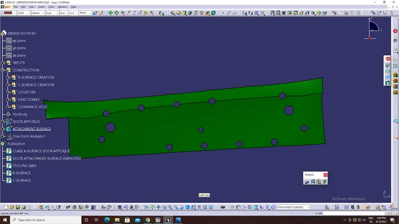
b. Door Attachment:
1. Isometric View:
2. Front View:
3. Right View:
4. Left View:
5. Top View:
Conclusion:
Solid Door Applique and Door Attachment with locators, ribs, clearance holes are created.
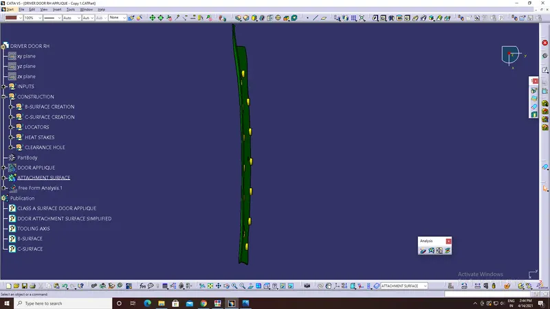
Draft analysis on the Final component and Class A-Surface is performed and it satisfies the draft condition.