Week 9 - Project 1 - Door Applique Design with Engineering Features
PROJECT 1-DOOR APPLIQUE DESIGN WITH ENGENEERING FEATURES
AIM :
To create the Heat Stakes and the locators considering the design rules and perform the draft analysis for the locators and heat stakes.
DRAFT ANALYSIS :
- No parts can be ejected from the tool if it is having a straight 90 degree profile from its base surface. A small draft angle is provided to each and every area of the component in order to get an easy removal of the component from the tool.
- Draft analysis technique is used to analyze whether our part model created in cad is manufacturable based on the draft condition applied. Here the part should get easily removed from the panel dies (in case of Sheet metal part) or Mold (in case of plastic).
- Here we are providing a direction in which components should eject inorder to get an easy removal of components from the tool. In other words it also lets us know whether the model is having a draft angle and how much is the draft angle from the tool direction.
TOOLING AXIS :
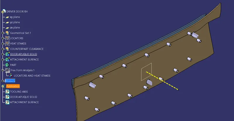
The tool axis is the parameter which decides whether the tool enters into mould or not as as it denotes the draft clearance angle where a moulded part is easily removed from the mould.
PROCEDURE FOR CREATING TOOL AXIS :
- Firstly we will be given with a class A surface which is looked as a asthetic and a smooth finish which is created with a Alias software workbench which is also known as a free imagination surface.
- For that class A surface we need to check a boundaries first to check any unattached faces is present in that surface.
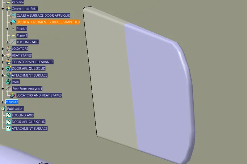
- The below is the image of a class A surface which is given as a input.
- So next we need to take a dummy tool axis to get a real tool axis.
- Next we take inclined lines to the surfaces we assume that draft is required.
- Then we intersect the both the lines and the bisecting line will be the tooling axis.
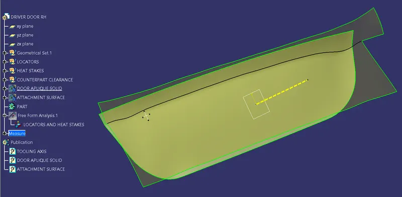
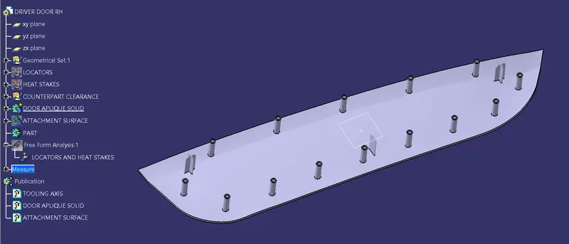
Here in this door applique the tooling axis is taken normal to the attachment feature.
DESIGN OF LOCATORS :
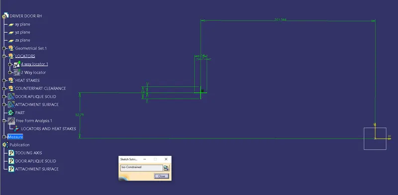
Geometric sketch :
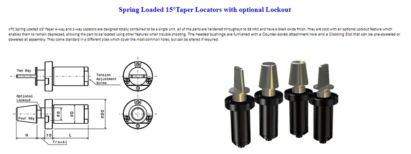
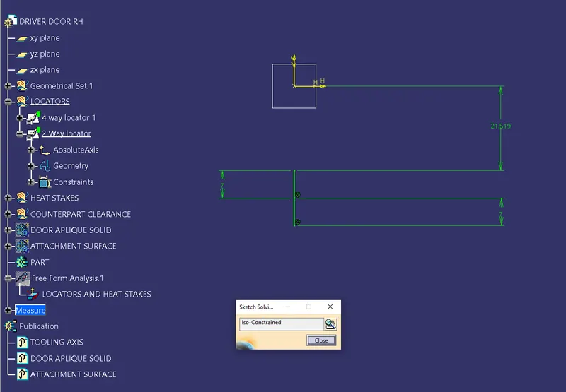
Four way locator :
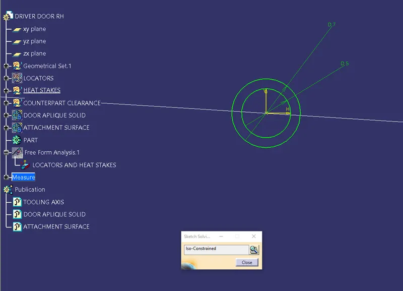
4-way mean you prevent movement at 2 axis (+X, -X, +Y and -Y) on the plane. Generally you have cylindrical pin on the fixture and circular hole at workpiece part.
Two way locator :
2-way mean you prevent movement only at 1 axis on the plane. And generally you have cylindrical pin on the fixture and slot hole at workpiece part.
We use generally one 4-way and one 2-way at the same time. We need freedom of movement. Because the distance between pins at the fixture or the holes at the workpiece might not fully accurate.
Heat stakes :
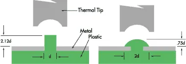
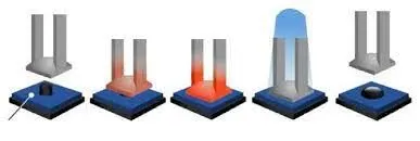
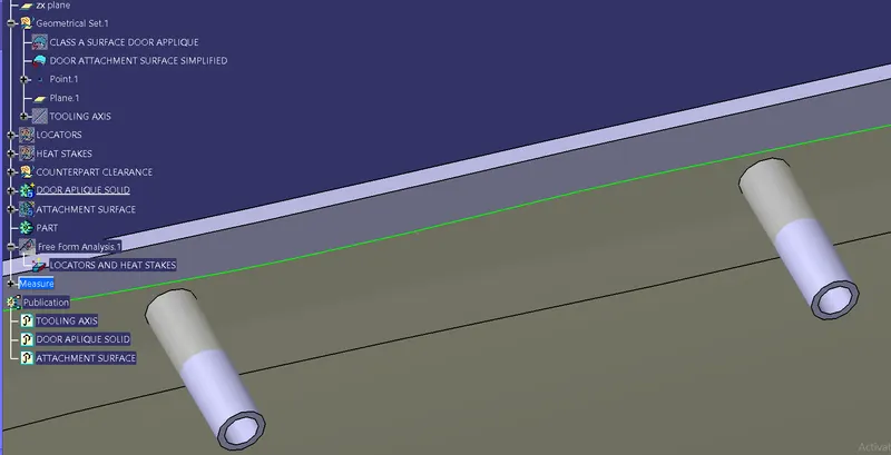
Heat Staking is a pulsed-heat process to join two or more parts out of which one at least is made of plastic. The process is to deform the plastic material using heat and force at a set process time. The bond is made by partially de-forming the plastic part in order to fix the other.
Heat Staking makes it easy to bond metal to plastic and is commonly used in high volume/low cost applications such as automotive, IT and consumer appliances.
Shaping Plastic Using Heat and Pressure :
The plastic is deformed by heating it to a temperature above the glass transition temperature. Super-heated air or a thermode is used for this. Pressure is then applied to create the stake. After the stake has been formed, the plastic should be cooled down again below the glass transition temperature. Cooling is performed under constant pressure to ensure good fixation of the parts. Compressed air can be applied for cooling when a thermode is used.
Heat is used to facilitate the creation of the stake. Heat control is critical, especially for glass-filled plastics which often have a process window of less than 10 degrees Celsius. When the temperature is too high, the glass fibers come out of the plastic which leads to a rough surface and adhesion to the thermode. If the temperature is too low, the plastic will crack due to cold deformation.
DOOR APPLIQUE :
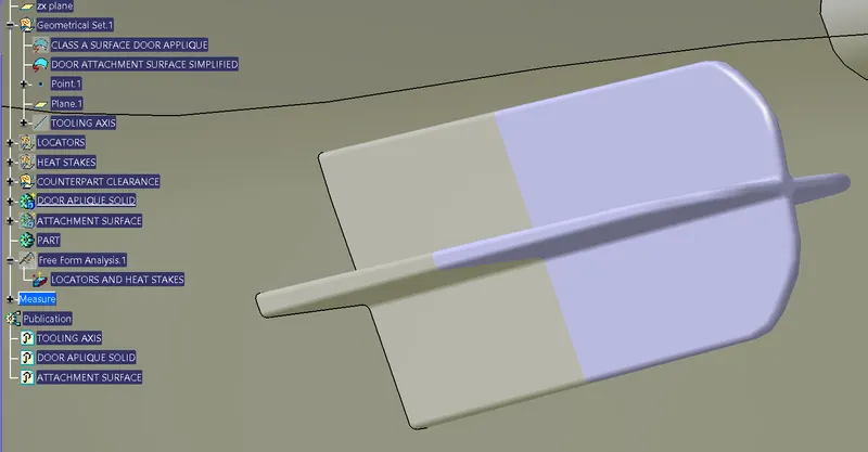
DOOR APPLIQUE WITH ATTACHMENT FEATURE :
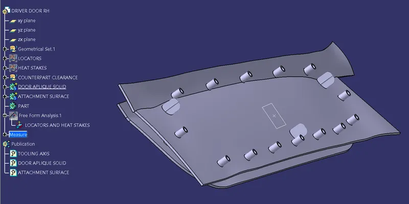
The clearances for the locaters with counterpart should be 0.1mm and for the heat stakes should be 0.5mm.
The draft for the locators and the heat stakes should be 0.5 degrees.
DRAFT ANALYSIS PROCEDURE :
Change the view mode to Customize View Parameters and select Material option from the view mode.
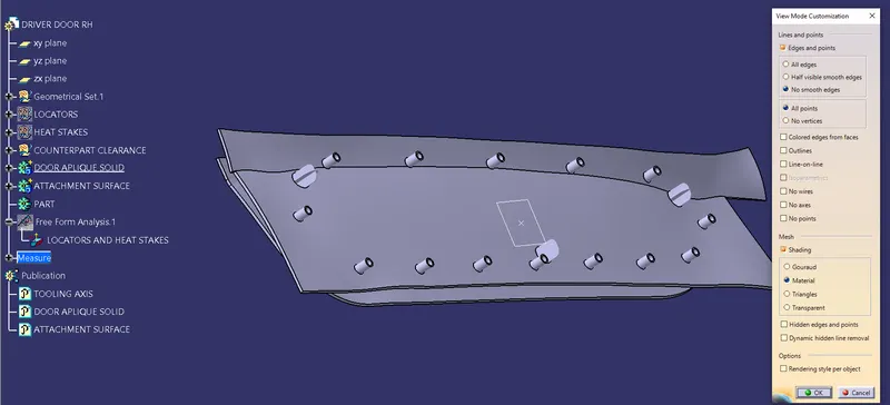
Insert > Analysis > Draft Analysis
- Draft Analysis dialog box with colour scale (with quick analysis mode) appears on the screen. So the first mode option is the quick analysis mode and second is full analysis mode. Here the quick analysis mode is used.
- Change the value of green according to the draft angle provided to the part.
- To get a clear picture, either we need to adjust the compass by holding the marked region of compass and dragging it towards the opposite direction or by selecting the inverses draft direction option inside the direction
of Draft Analysis. - After getting green colour on the component, try to adjust the compass using the knob, and adjust the direction of the compass to get green on the entire top panel region.
- Try zoom in and check if each and every region of the panel is showing green, if in some region, red or blue is showing instead of green.
- If any errors is present try to adjust the compass direction to optimise the errors.
- If any error is unable to change we need to use the side cores for that positions.
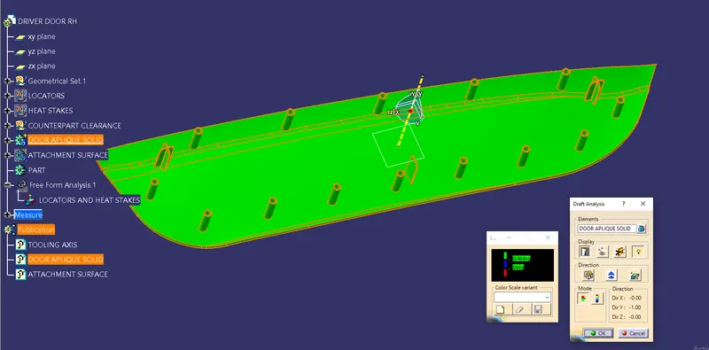
Here blue colour shows 0.48 degrees which is given as entry draft angle for the locators and heat stakes.
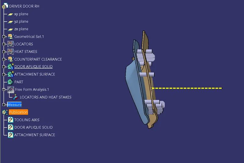
FRONT VIEW :
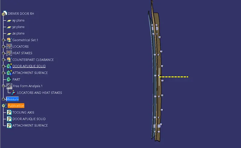
TOP VIEW :
ISOMETRIC VIEWS :
GOOGLE DRIVE LINK :
WEEK 9 PROJECT 1-DRIVER DOOR APPLIQUE AND ENGENEERING FEATURES