Week 9 - Project 1 - Door Applique Design with Engineering Features
DESIGN AND DRAFT ANALYSIS OF DOOR APPLIQUE
AIM
To perform design and draft analysis of door applique and also to perform draft analysis on it.
PROCEDURE
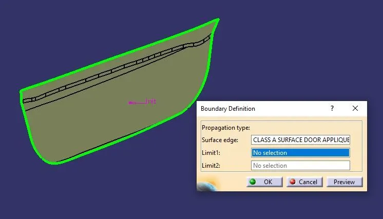
Door applique is one of the plastic part in the door area, it is an ornamental part. To design the door applique we need to check the input class-A for any discontinuities or any improper patches using the boundary command.
Tooling axis creation
Once after checking the class-A surface we have to create the class-A surface for the proper draft is available in the class-A or not.
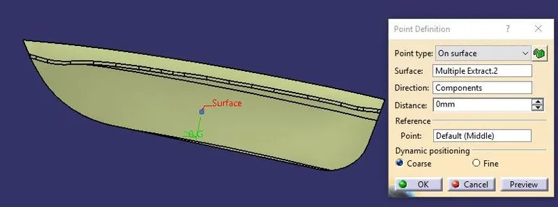
For checking draft angle in A-surface we have to create the tooling axis, to create the tooling axis we need to extract the surface from the A-surface or simply we can put a point on the geometrical zero of the class-A surface given.
Then we have to create the line on that point,by using the line command,the line should be perpendicular to class-A surface.
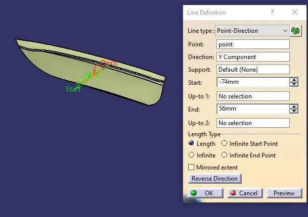
After creating that line, we have to check the draft analysis by using that line as tooling direction, if that line clears all the surface in that tooling direction then we can publish that line as tooling direction.
To perform the draft analysis, we have to put the material mode on the view mode and we have to select the draft analysis tool on the analysis tab, and we have to place the compass on the tooling axis and click on the surface of the class-A. We have to set the draft angle limit and check all the surfaces are having proper draft angle.
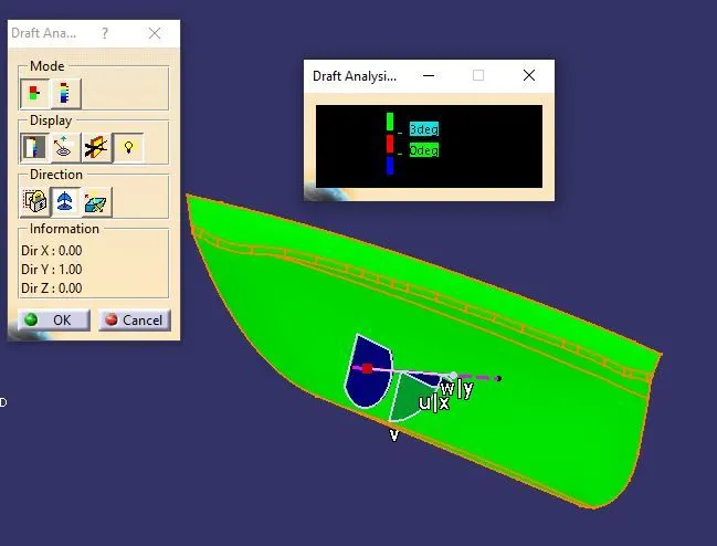
After checking the draft angle, we have to design the B-side surface we have to offset the class-A surface and we have to extrapolate the B-side surface with curvature continuity for small length, and we have to use the boundary command to create the boundary of the class-A surface after creating the boundary we have to create the sweep with the direction of tooling axis, with required draft angle.
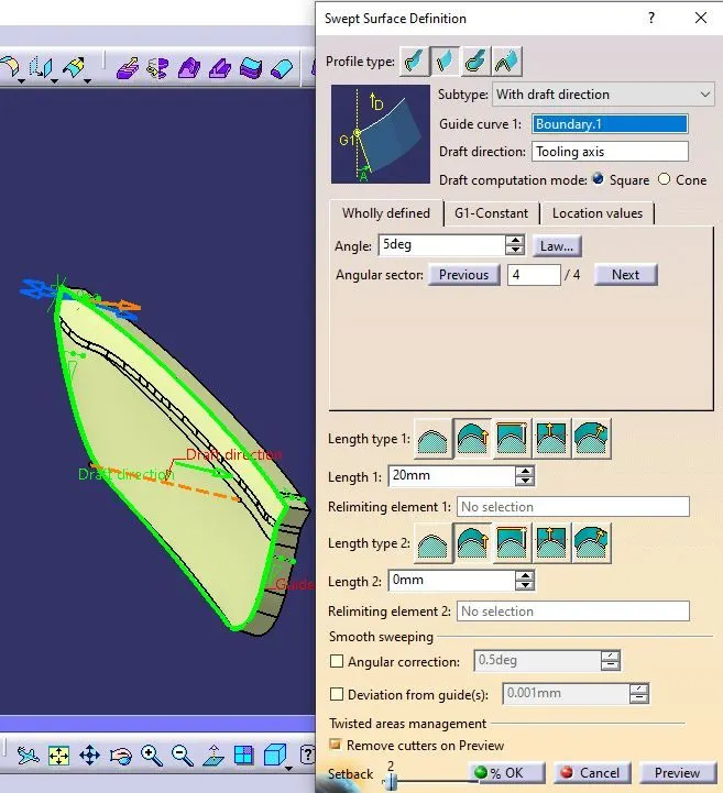
Then join the class-A surface with the sweep created, and finally trim the B-surface with the class-A surface to form the complete surface model of the part, then we have to use the close surface command in the part work bench to create the solid part from the surface model.
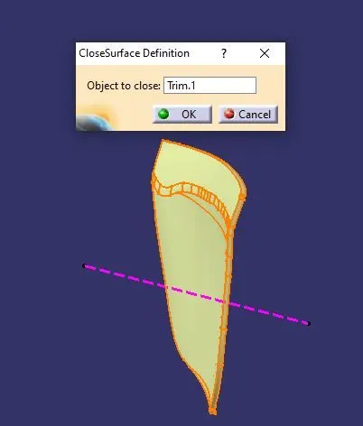
After creating the solid part, now we have to create the B-side features, here we are going to create the four way locator and a two way locator. To create the four way locator and two way locator we have to create a plane on the attachment surface and create the sketches on it.
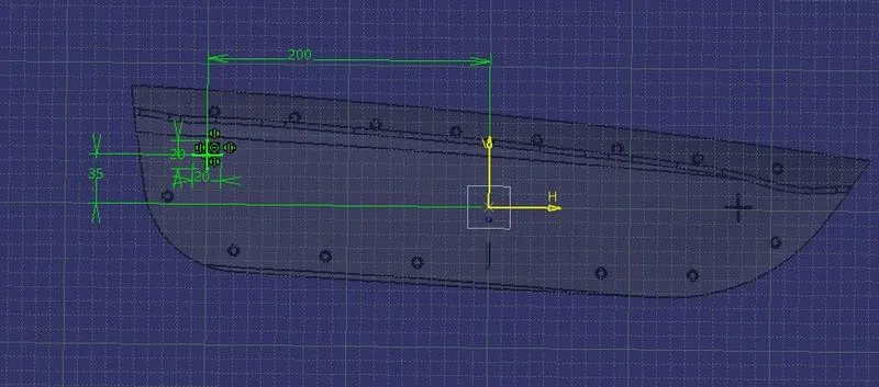
Then extrude that sketches using the thick option in the extrude, and also follow the plastic design rules for the height and the thickness of the locators, and always ensure that all the locators are in same height with respect to the attachment surface.
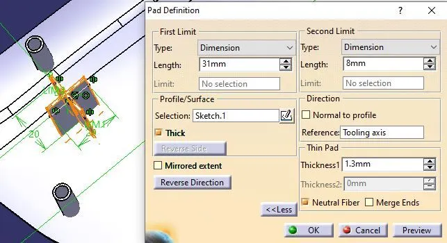
We should give proper draft angle for the attachment surfaces, that draft angle should be 0.5degree as per the plastic design rules, and select the tooling axis as the pulling direction. Then we have to apply the entry chamfer and the radius for every sharp corners as per the plastic design rules.
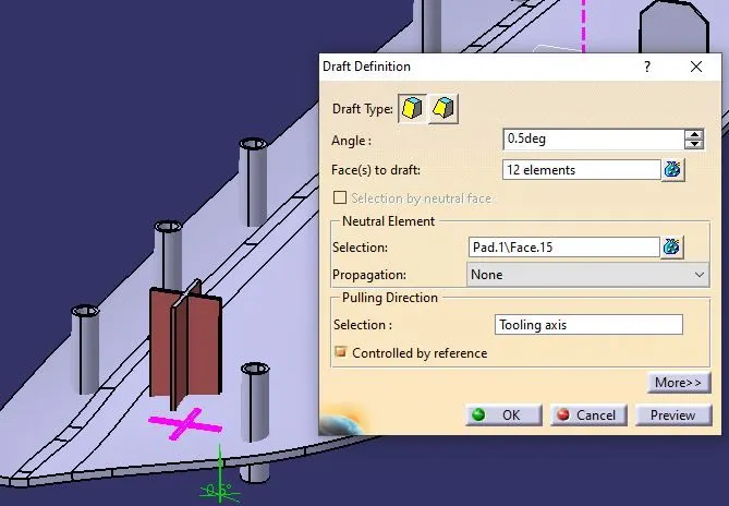
We can copy paste the one locator with paste special option as result with link, and can translate the locator to the area where we want.
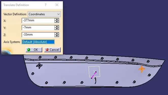
In the above image the translate is done using the coordinate option, and the orange colour highlighted object shows the location after translation.Then we have to use the suitable Boolean operation to attach the locator to the door applique.
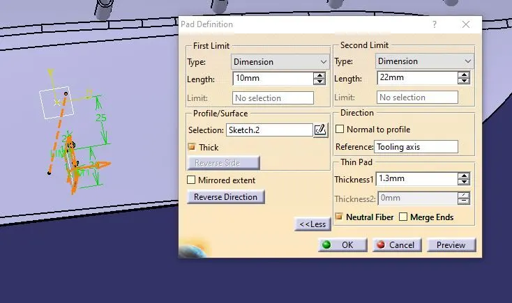
After designing the four way locator we have to design the two way locator. By following the same method the image of the two way locator is also shown below,
Now we have to design the heat stakes, heat stakes are used in the automobile sector to simplify the assembly of two components, heat staking process is similar to the method of riveting, but here the heat and pressure is applied in the plastic component to another metal component or a plastic component.
There are some advantages of using heat stakes, they are
- Using heat stakes will simplify the machinery
- Multiple fastening points
- Allows high density of weld when compared to hot air cold form or ultrasonic welding.
For designing the heat stakes we have to extract the boundaries of the class-A surface and use parallel curve option and create points on it by using the point command.
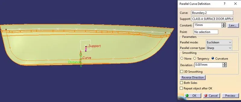
For designing the heat stakes sketch, we have to use the same plane which we used to create the locators and make sure we have proper draft values also, and the pulling direction should be the tooling axis.
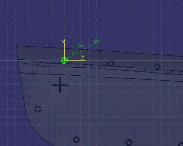
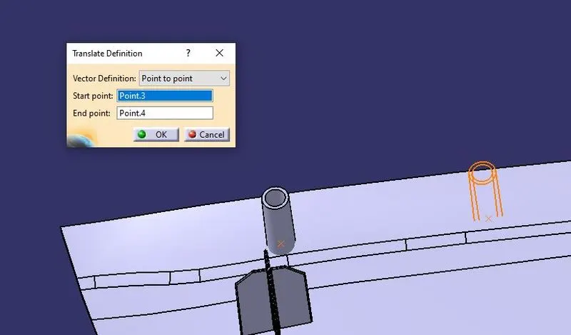
We can copy paste the heat stakes and paste as result with link and here, use the point to point translation of the positioning of the heat stakes and use the points created on the boundary as the reference points for the translations.Always the heat stakes should have lesser height than the height of the locators, for the fixation purposes.
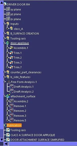
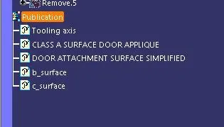
Now create another body and assemble all the heat stakes into it, and perform a union trim operation with the door applique so we can maintain the proper tree structure,publish the A-surface, B-surface, C-surface and also the tooling axis, for ease of access, we can publish them by using the tools dropdown publication option.
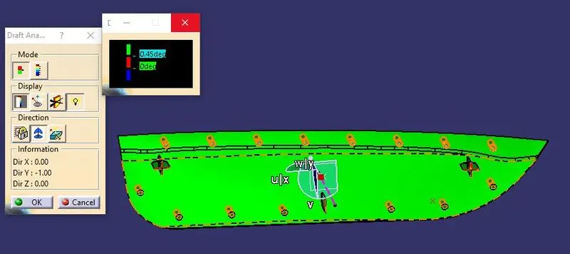
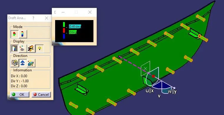
Now we have to perform the draft analysis for the B-side of the door applique, here we have to follow the same steps we have followed for the class-A surface draft analysis, and we have to reduce the value of draft by 0.45 degrees, then we have to find the deviations on the draft angles.
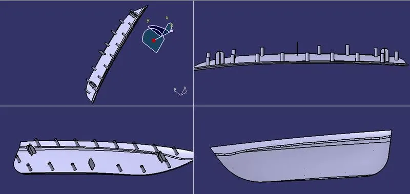
Finished part is shown below,
CONCLUSION
Thus the design of door applique is done and draft analysis is also performed, and the B-side features are also created.