Week 9 - Project 1 - Door Applique Design with Engineering Features
TREE STRUCTURE
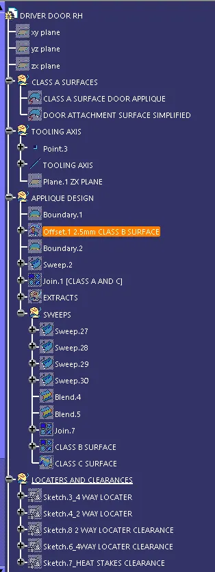
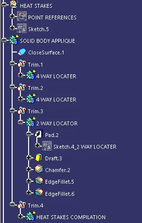
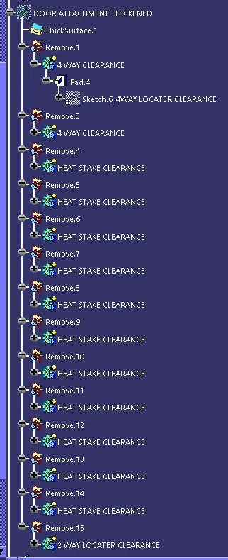
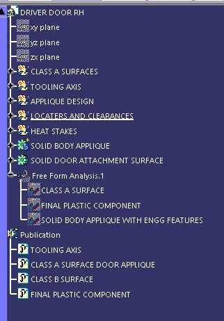
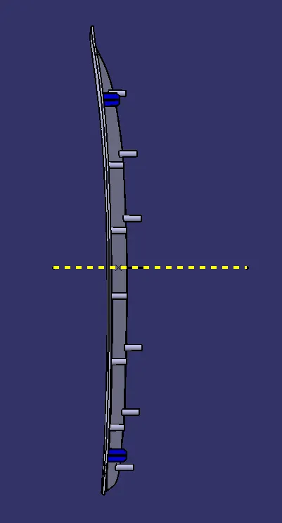
DOOR APPLIQUE WITH ENGINEERING FEATURES
FRONT
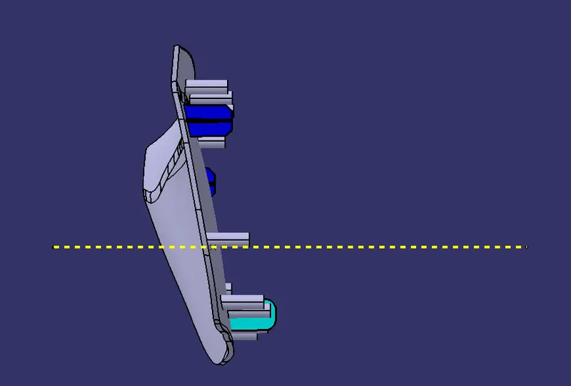
SIDE
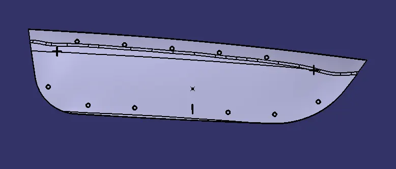
TOP
ISO
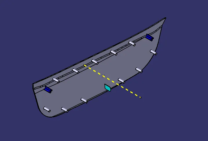
DOOR APPLIQUE WITH DOOR ATTACHMENT FEATURE CUM CLEARANCES IMAGES
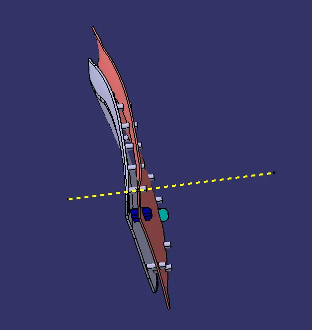
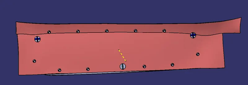
GENERATION OF TOOLING AXIS
TOOLING AXIS: It is an Axis which indicates the direction in which the mould/cavity opens. It can also help in designing the component according to the drafting needs of an Industry.
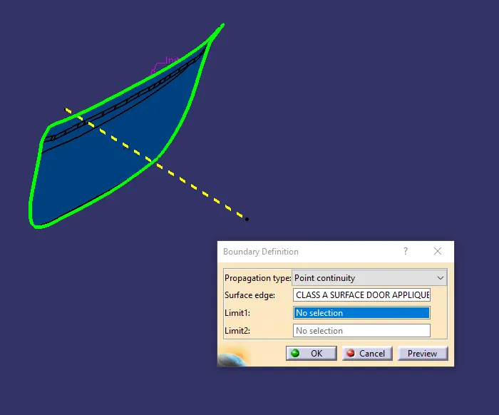
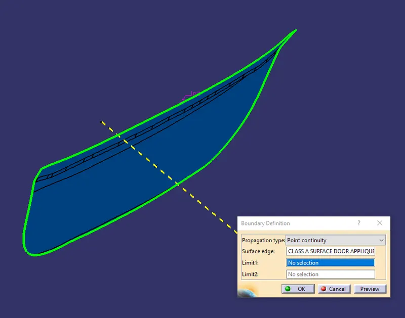
At first the component is checked for any discontinuity in the line using Boundary Tool  .
.
 [1]
[1]
The above image ensures that the component has no discontinuity in its line.
BISECTING METHOD:
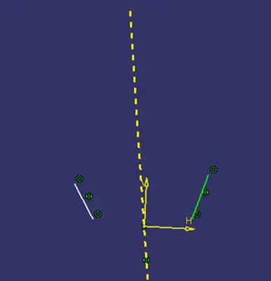
Bisecting Method is used to generate main tooling axis by bisecting or dividing the two dummy tooling axis generated from intersection of planes.
It can be created in both Workbenches. [Part and GSD]
 [2]
[2] 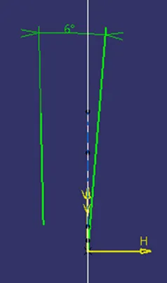 [3]
[3] 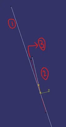 [4]
[4]
[pic 4] - 1 and 2 are Dummy tooling Axis bisected using a Line using Line Definition Tool  which gives us the Main Tooling Axis.
However in Door Applique we make use of Line Definition Tool to generate both Main Tooling Axis Normal to the surface [pic 6] as explained below.
A Point is generated at centre of the component [Class C Surface].
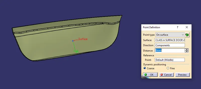 [5]
[5]
A line normal to the surface is generated passing through the point using Line Definition Tool as shown.
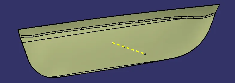 [6]
[6]
GENERATION OF CLASS B AND C SURFACE
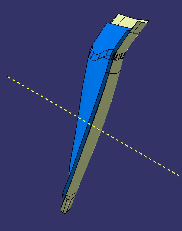 [7]
[7] 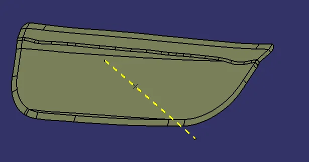 [8]
[8]
Class B Surface is generated by offsetting the Class A surface to the required thickness [2.5mm] in the direction of Door Attachment Surface [given] and extrapolating it to make the trim easier.
Class C Surface is generated by extracting the boundary line of Class A Door Applique using Boundary Tool available in Operation Toolbar [pic 9] and generating the surface using Sweep option with required draft [min 3 deg] along the tooling axis [pic 11].
 [9]
[9]
 [10]
[10] 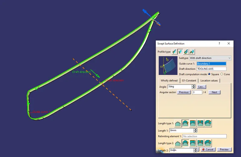 [11]
[11] 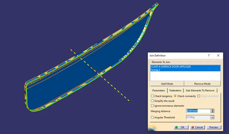 [12]
[12]
[pic 12] - Class A surface and Class C joined using Join Tool 
This resultant Join surface was trimmed with Class B surface to get the Final plastic Component with thickness 2.5 mm.
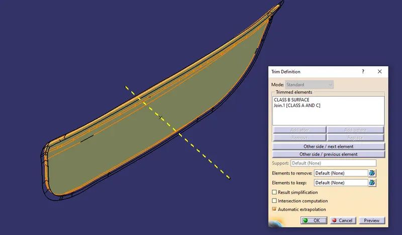 [13]
[13]
Finally a Solid Door Applique is generated using Closed Surface Tool  available in Part Workbench.
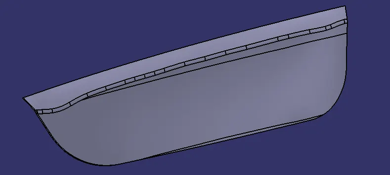 [14]
[14]
GENERATION OF ENGINEERING FEATURES
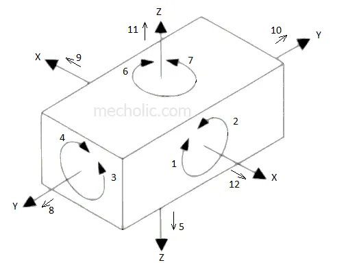
There are 12 Degrees of Freedom [DOF], Namely
Translation Movement along X axis [+/-]
Translation Movement along Y axis [+/-]
Translation Movement along Z axis [+/-]
Rotational Movement along X axis [Anti-clockwise and Clockwise direction]
Rotational Movement along Y axis [Anti-clockwise and Clockwise direction]
Rotational Movement along Z axis [Anti-clockwise and Clockwise direction]
 [15]
[15]
Locaters and Heat Stakes are used to restrict these movement according to the requirement.
2-WAY/4-WAY LOCATERS and HEAT STAKES:
 [14]
[14]  [15]
[15] 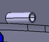 [16]
[16]
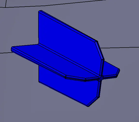
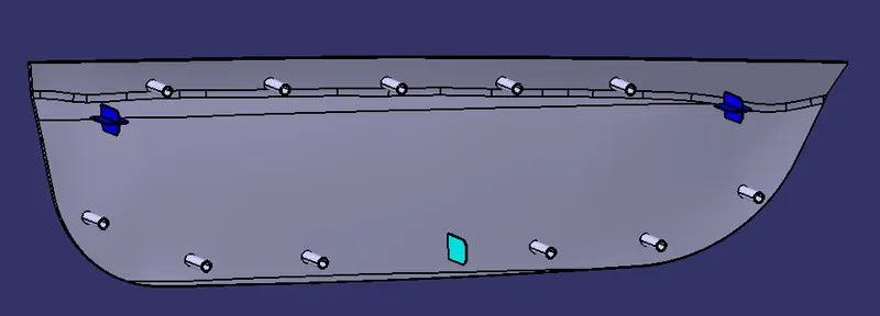
4 Way Locater [pic 14] used to arrest movements in 4 directions or otherwise 2 Axis [+/- X axis AND +/- Y axis].
2 Way Locater [pic 15] is used to arrest movements in 2 directions or otherwise one axis [+/- Y axis OR +/- X axis].
Heat Stakes [pic 16] are used to allow movements only in one direction.
Heat Stakes are also known as thermoplastic staking is the process of joining two dissimilar materials together. In heat staking we use local heating and cooling to raise the temperature of plastic components and allow plastic reforming to be carried out.
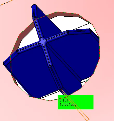
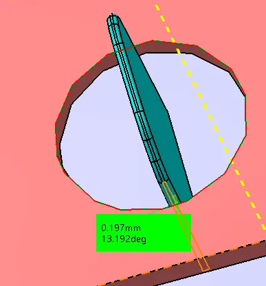
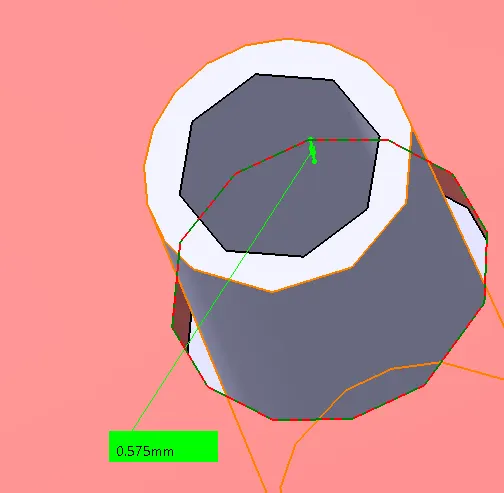
These locaters used to fit in the Door attachment surface with clearance 0.1mm per side for 2 and 4 way locaters [pic 14.1 and 14.2] and 0.5mm per side for Heat stakes [pic 14.3] as shown below.
 [14.1]
  [14.2]
  [14.3]
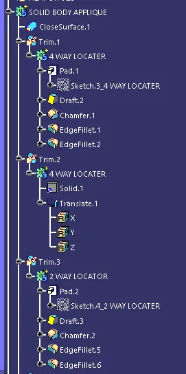
Locaters are created using Pad operation in Part Workbench and Boolean [Union Trim] it with the solid Door Applique [pic 17, 20] and its clearance [pic 14.1 and 14.2] in Door Attachment is created using pad operation and Boolean [Remove] it with the Solid Door attachment part body.
Heat Stakes are created using Pad operation available in Part Workbench and Boolean [Assemble] it with Door Applique Part body [pic 18, 20] and its clearance are created using Pad operation in Part Workbench and Boolean [Remove] it with the thickened door part body. [pic 19, 21].
[pic 19] - shows the boolean of Clearances of both Locaters and Heat Stakes.
 [17]
[17] 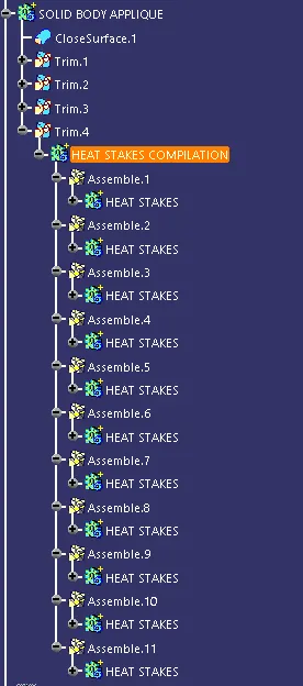 [18]
[18] 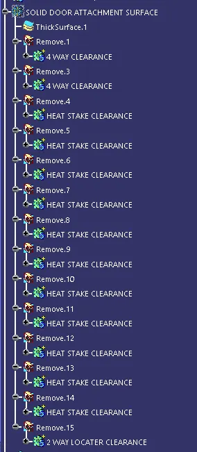 [19]
[19]
Advantages of Heat Stakes:
- Performs in one machine cycle and motion rather than individual motions required for each fastener.
- Not need to change the Base material
- Creates almost no mechanical stress because it operates through a precise control and application of the temperature and pressure to cause the reforming of the plastic that it makes contact with.
- Better compared to Ultrasonic plastic Assembly where it uses ultrasonic vibration to generate heat and assembly process which have been known to effect or damage sensitive electronic components and cause cold solder joints or stress cracks in the printed circuit boards.
- Variety of Shapes are possible via customized design tools.
 [20]
[20] 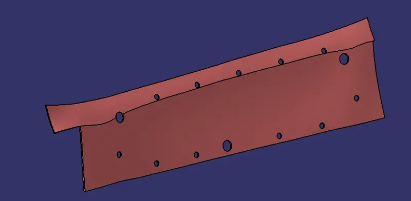 [21] [21.1]
DRAFT ANALYSIS OF CLASS A SURFACE AND FINAL PLASTIC COMPONENT
DRAFT: When the molten plastic is completely ejected into the molded cavity and it is allowed to cool it tends to shrink to the core side of the mould and thus there deveolps a friction between the part [final output] and the mould. To overcome this drafting is required. It is required on all parts in the direction of mold movement in order to allow parts to release or eject from the mold properly
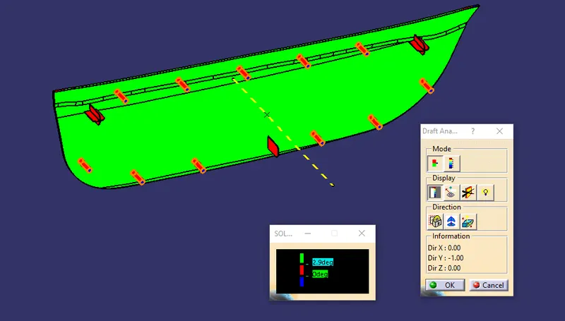
Drafting Analysis is used to generate computational analysis of the component clearing the mould cavity without any damage [by friction] between the final component. It checks whether the Main Tooling Axis is correct or not thereby analysing the draft of the component. It shows whether all faces of the component has the required draft or not using value assigned colour codes [pic 2]. It further helps us to detect corrections in the earlier stage [i.e design] thereby preventing the cost and damage to the component.
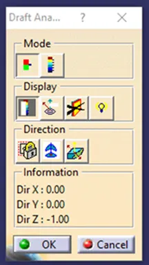
At First, Compass Tool  is used to position the co-ordinate plane into the main tooling axis of the component and locked using Lock Tool
  .
.
This compass tool is available in the drafting Dialogue Box along with Lock and Analysis under Running point Tool  in the display section of the dialogue box.
 [22]
[22]
CLASS A SURFACE
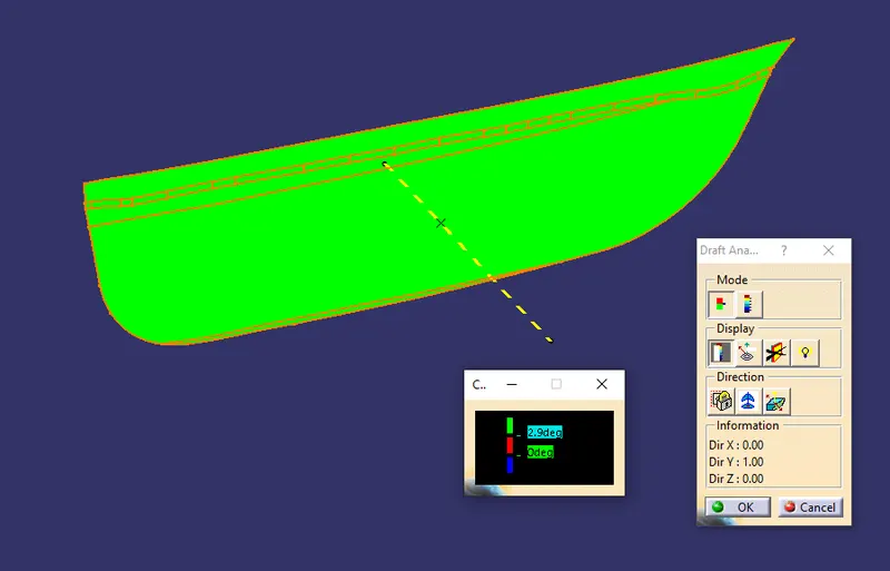 [23]
[23] 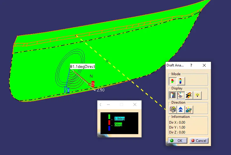 [24]
[24]
[pic 24 ] - shows Running point Tool to check the draft on the face.
OBSERVATION:
The above image indicates that the given Class A surface satisfies the minimum draft requirement of 3 mm and it is shown in Green Colour.
COLOUR CODE IDENTIFICATION
|
RED |
0 < A < 2.9 |
|
GREEN |
0 < A > 2.9 |
|
BLUE |
INVERTED |
FINAL PLASTIC COMPONENT
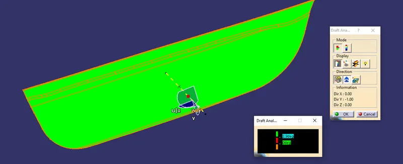 [25]
[25] 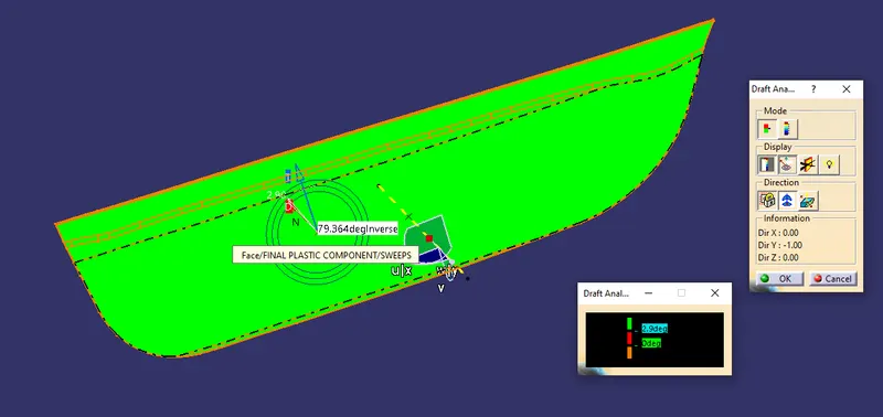 [26]
[26] 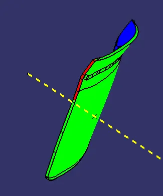 [27]
[27]
[pic 26] - shows Running point Tool to check the draft on the face.
OBSERVATION:
The above image gives same analysis as that of Class A Surface but with slight exception as we can see some red patches around the corner as shown in [pic 27].
The Blue colour indicates that the faces are inverted which inturn indicates that it could clear minimum drafting angle provided that the tooling axis is reversed or inverted or changed.
FINAL COMPONENT WITH ENGINEERING FEATURES
 [28]
[28]
OBSERVATION:
Here the observation is same as that of Class A surface and final plastic component. But here the red patches are observed in engineering features indicates that it did not clear the minimum draft clearance. It is suggested that to change the orientation of the tooling Axis w.r.t engineering features liike changing the angle of the tooling axis to get desired output.
CONCLUSION:
The Current Analysis highlights some improvements with [w.r.t Tooling Axis] where better drafting can be achieved. Hence the component can be moved further to the Manufacturing after incorporating the necessary changes.