Week 9 - Project 1 - Door Applique Design with Engineering Features
ANSWER:
AIM:
Create the Door Applique Plastic component through the given Class-A surface. To begin with, the tooling axis for the given Class-A Surface should be created meeting the requirements of the draft angle and at the end perform the Draft analysis on the model.
Create the Heat Stakes and the locators considering the design rules mentioned in the video for the door applique.
CREATING A TOOLING AXIS :
tooling axis is created by class A surface
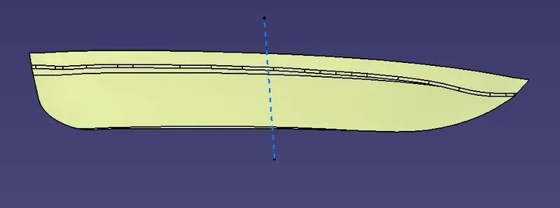
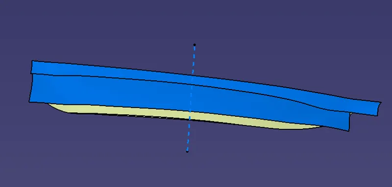
make a solid body by using the class A surface.
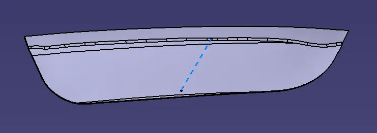
Hence, the solid body is created by class B and C surfaces.
4 Way locators:
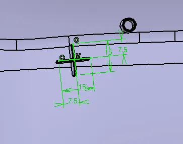
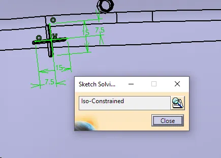
after the location of the 4 Way locator translate the 4 Way locator to another side at a distance. and trim with the solid body
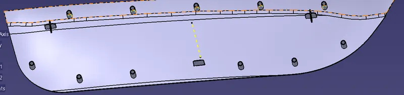
2 Way locator:
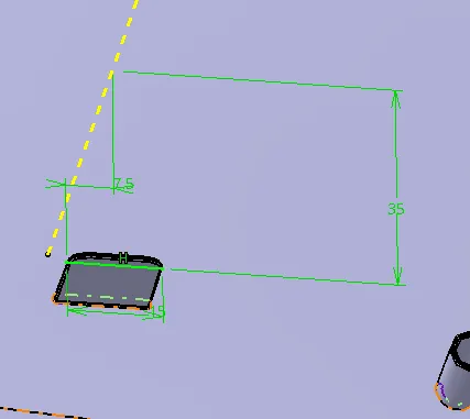
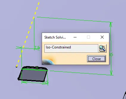
heat stakes:
extract the surface from the body and make a boundary for the body and create a point on the boundary line
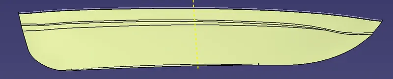
then offset the plane to 2.5 mm
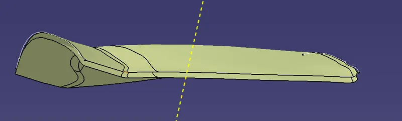
extract the boundary for the offset surface. make a point by extracting and using parallel on curve command use on both sides of the surface.
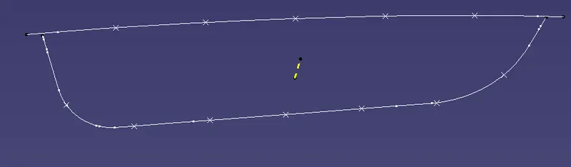
after creating the points draw a sketch on the points
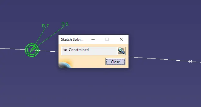
after drawing the sketch pad the sketch for some height translate all the heat stakes through the points on the boundary line
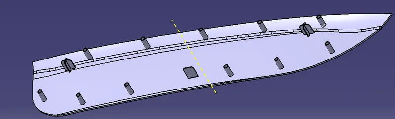
assemble all the heat stake bodies and make one body
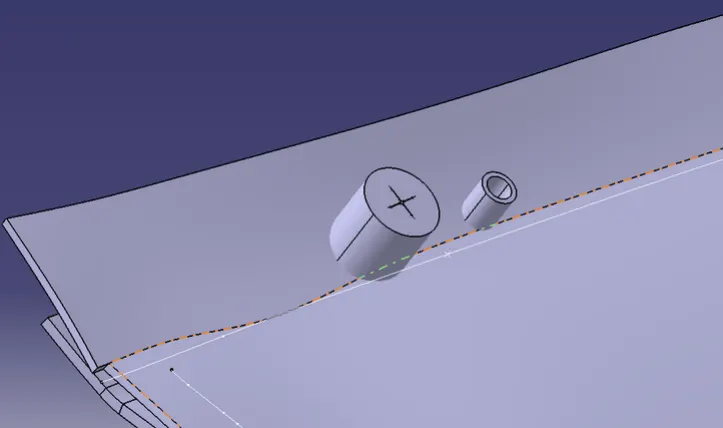
graft to it
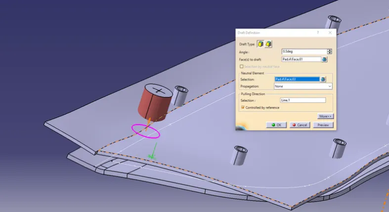
Make that hole for the other two locators also
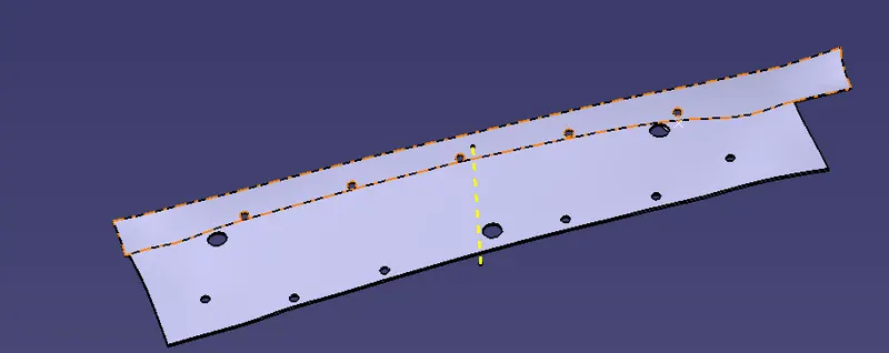
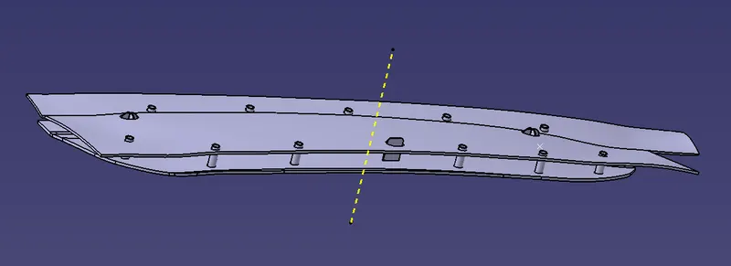
THE HEIGHT OF THE STEAK AND THE LOCATORS ARE BELOW 5 MM FROM THE DOOR REFERENCE, SO THAT THERE WILL BE NO PLASTIC DEFECTS
FINAL BODY:
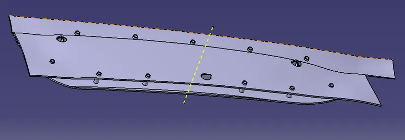
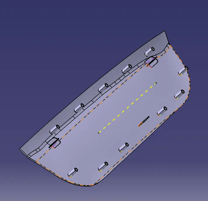
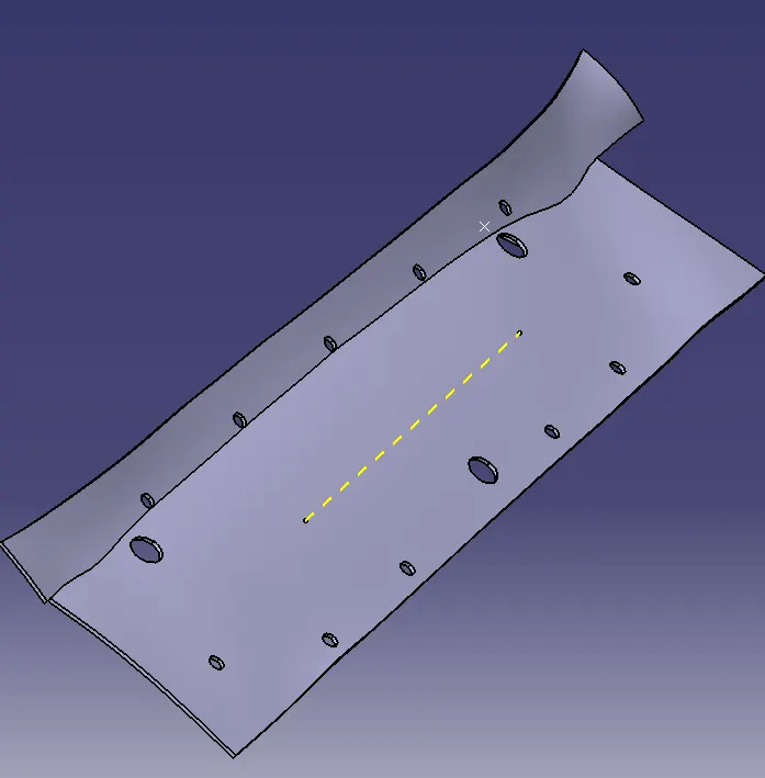
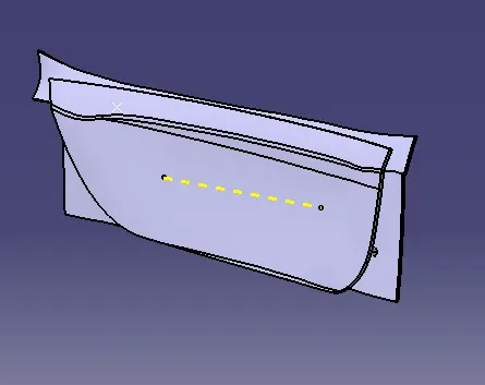
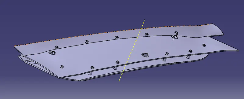
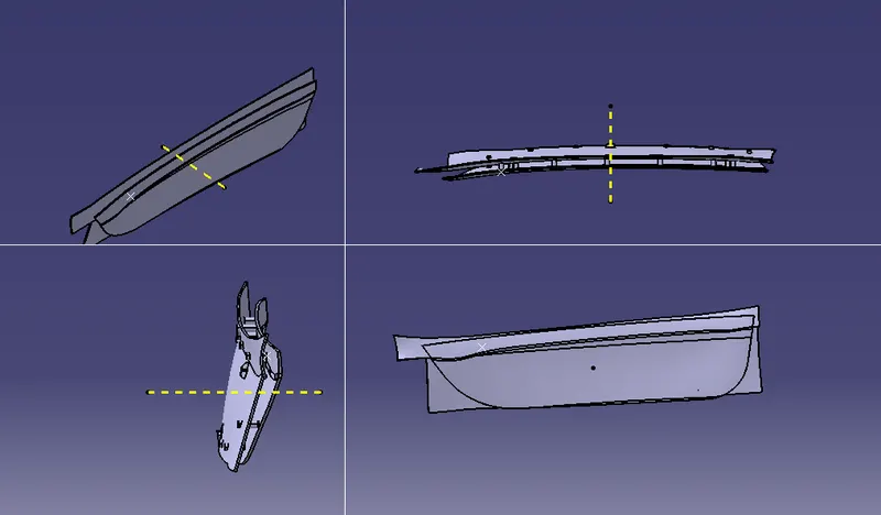
ALL VIEWS:
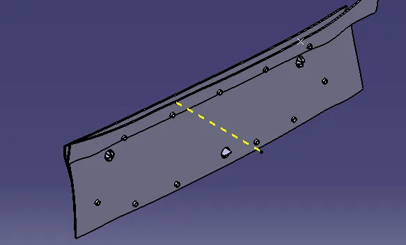
ISOMETRIC VIEW:
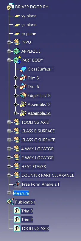
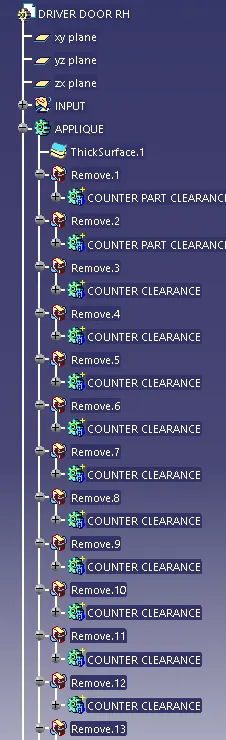
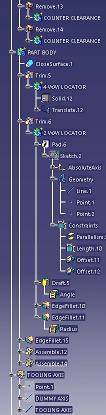
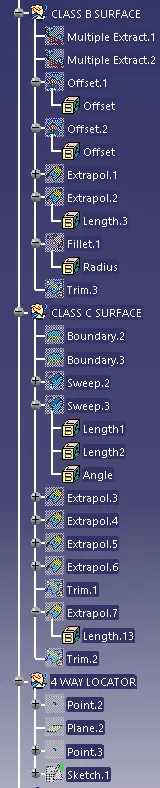
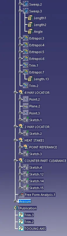
tree structure;
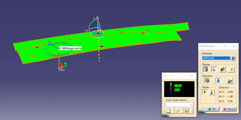
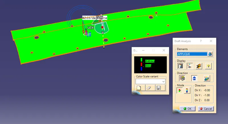
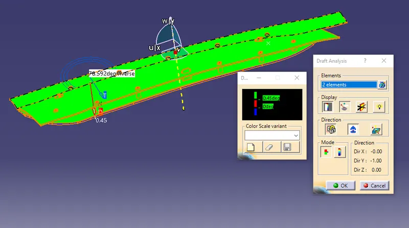
DRAFT ANALYSIS:
draft analysis for applique
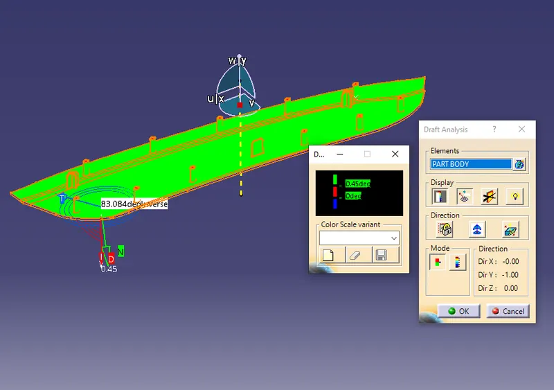
draft analysis for solid body
CONCLUSION:
the Door Applique Plastic component through the given Class-A surface is created, heat stakes and locators are designed as per design rules for the door applique. draft analysis is performed.