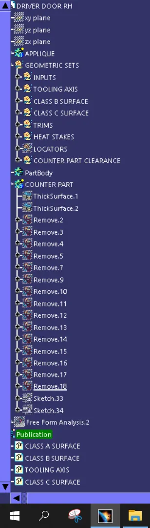
Week 9 - Project 1 - Door Applique Design with Engineering Features
AIM: To create a Solid APPLIQUE from the given Class A Surface as Input and create Engineering features for location and fixation by using Heat staking technique.
OBJECTIVE:The objective is to create APPLIQUE using Class A Surface along with draft analysis and following the OEM Design standards.
CLASS A SURFACE:
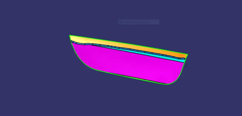
CLASS B SURFACE:
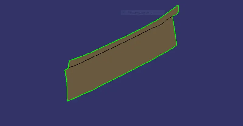
CLASS C SURFACE:
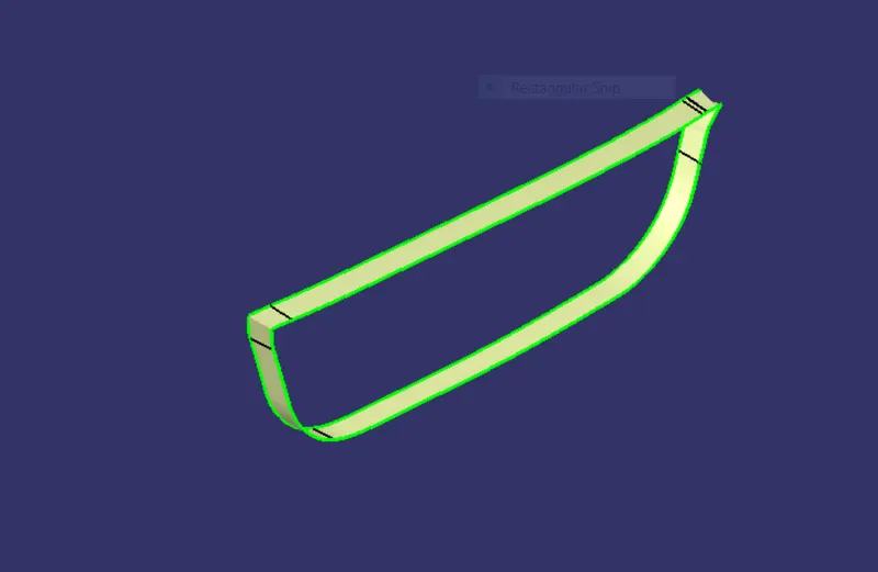
TOOLING AXIS:
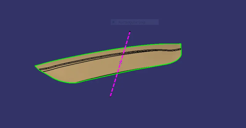
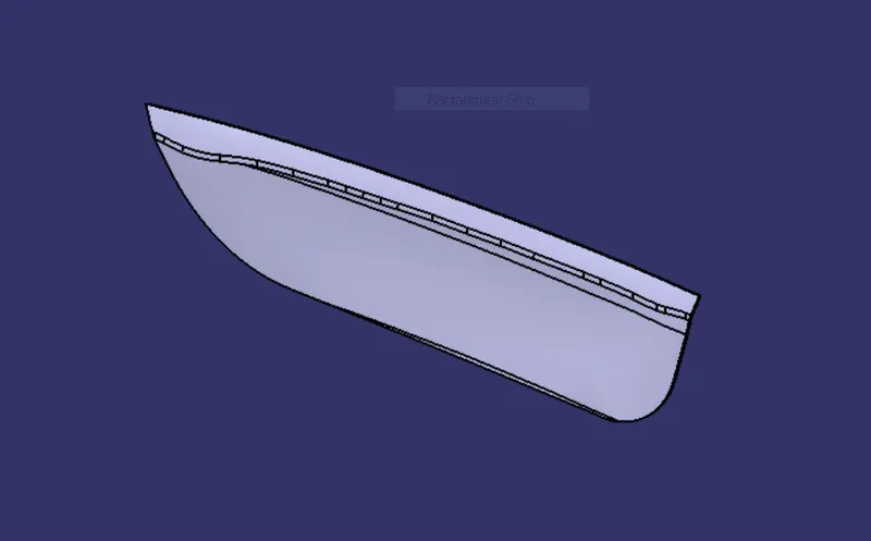
SOLID BODY PART:
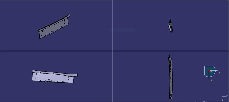
TOOLING AXIS CREATION:
- Class A surface is first analysed for creation of tooling axis which tells about the direction of the mould or core and cavity slides.The tooling axis plays a vital role in the plastic design as there should be clearance between the tooling axis and mould.
- The minimum of 3 degree draft angle is provided on the surfaces which are 90 degrees to avoid the Interference between the mould and Injection moulding machine.
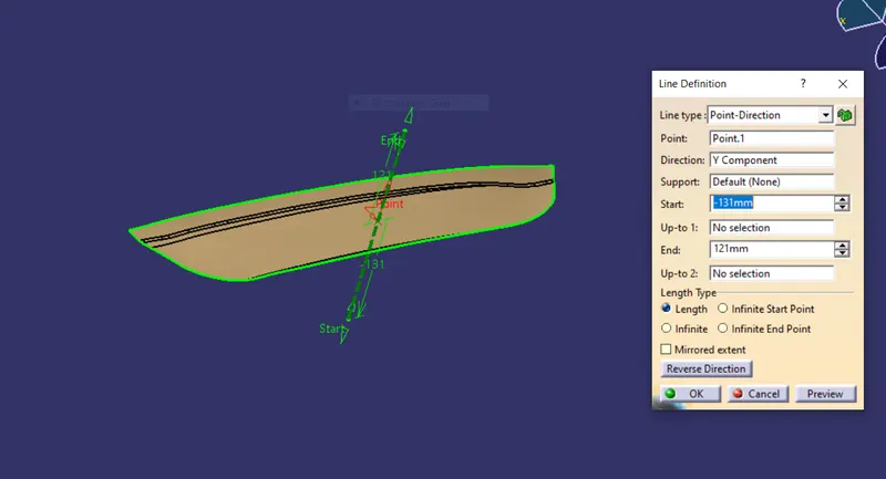
- Here there are NO side faces for the applique , so here we drawn a centre line to the base surface and treated it as the TOOLING AXIS.
- The line is renamed as the TOOLING AXIS and publishes it for ease handling the axis and changing its graphic properties.
DRAFT ANALYSIS:
- Draft angle is nothing but the amount of the taper is provided on the core and cavity for ease ejection of the mould after cooling.
- After Injection moulding the plastic parts shrinks and gets stuck to the core and it will make it difficult to remove the plastic part.
- If no draft or taper is provided on the core and cavity the inner layers of the platic part will undergo wear and tear and there will be NO smooth surface finish.
- The draft angle is provided on both the inner and outer walls of the core and cavity.
- The Nominal draft angle is 3 degrees
- The 5 degree draft can be given by the manufacturing cost will be more.
- The 7 degree draft is given for the textured surface
STEPS FOLLOWED FOR THE DRAFT ANALYSIS:
- The part created has to be changed to the material mode.
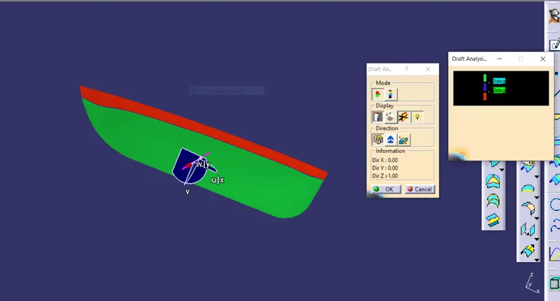
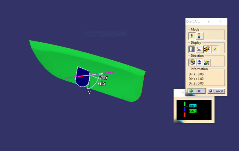
- compass is enabled and aligned to the tooling axis.
- Lock command is used to lock the position of the compass.
- colour codes are classified and draft angle is analysed.
- Running point analysis is used to display draft angle at a specific position.
DRAFT ANALYSIS ON CLASS A SURFACE:
DRAFT ANALYSIS ON SOLID BODY PART:
PLASTIC DEFECTS:
1.Flow Lines
2.Sink
3.Weld Lines
4.Vacuum Voids.
5.Shorts Shot
6.Burn Marks
7.Flash.
- The above are the major defects in the plastic manufacturing in most of the cases it can be avoided in the product design stage itself.The flow lines,sink marks occur due to the varying thickness which can be controlled within the design stage.
- The vacuum voids occur,burn marks occur due to the high temperatures of the molten plastic and low viscosity of molten plastic.
- The Excess molten plastic is escaped from the parting surface and it will be removed with the help of knife or shaped objects. As a product designer we need to take care to make the parting surface should be on the B surface.
RIBS:
Ribs are used as an economical stiffness or strength in the plastic components without increasing the thickness.
Ribs facilitates as :
1.They can be used for locating and arresting purposes.
- Providing alignment for the mating purpose.
3.Acting stops or guiding mechanisms.
DESIGN RULES FOR RIBS:
The major factors to remember while making Ribs are:
1.Thickness
2.spacing
3.Rib Height
4.Radius.
5.Draft Angle.
6.Location
Some standard dimensions for designing Ribs:
1.The Rib Height or depth can be maximum of 5x of component thickness.
2.Draft angle should be 0.5 degree minimum value
3.The radius value for the fillet should be 0.25 mm.
4.We can use two individual ribs in place of one long rib , the spacing between the two ribs should be 2t.
Here ‘t ‘represents the Thickness of the components.
The above standards are used for the ribs features faced inside the surface that customers will see.
3-2-1 PRINCIPLE:
If we need to constrain any object ,the object should be constrained in 12 degrees of freedom or 3 Translational motions along x,y and z and 3 Rotational motions along x,y and z.
Constraining Applique Against Main Door:
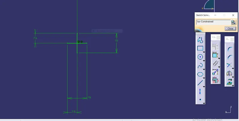
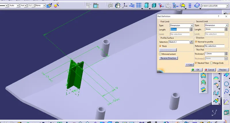
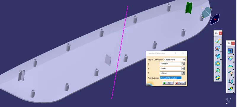
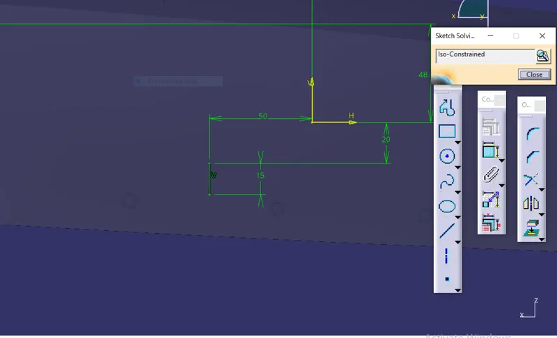
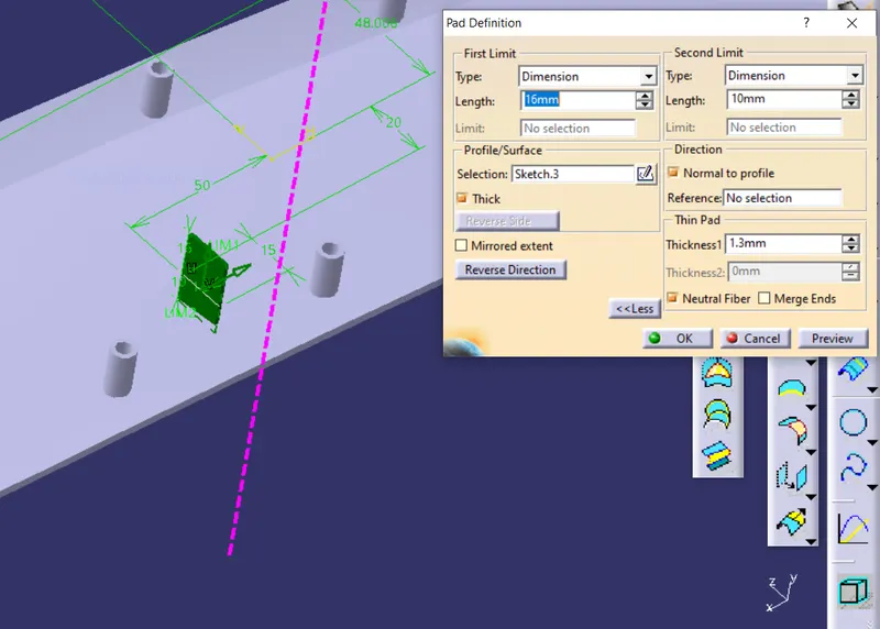
- Here I have created two 4 four way locators and a two way locator for locating the applique to the main door panel.
- By using the above 4 way locator and a two way locator we will constraint the applique in 11 directions and the last degree of freedom will be constrained in the direction of fixation to the main door.
HEAT STAKING:
- Heat staking is a welding technique or assembly technique used for joining the plastic component to a plastic or metal component.
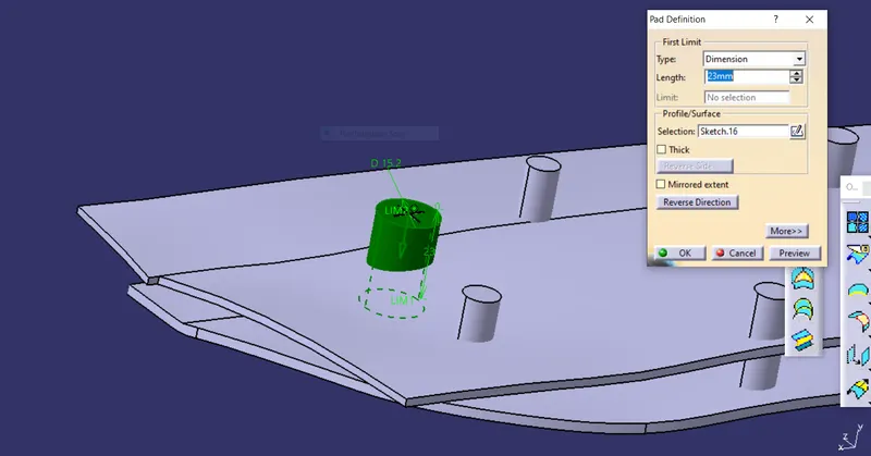
- In this process a boss stud is projected in the child body and a hole is made in the parent body the stud is melted and formed to solidify on the parent body.