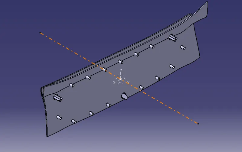
Week 9 - Project 1 - Door Applique Design with Engineering Features
Project 1 - Door Applique Design with Engineering Features:
Objective:
Create the Door Applique Plastic component through the given Class-A surface. To begin with, the tooling axis for the given Class-A Surface should be created meeting the requirements of the draft angle and at the end perform the Draft analysis on the model. Create the Heat Stakes and the locators considering the design rules mentioned in the video for the door applique.
Tool:
Catia v5
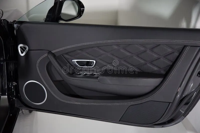
What is door applique?
A car door applique is used in the door panel to provide an aesthetic look to the door panel. There are various engineering features in the plastic part, There are a lot of defects that can occur in plastic part manufacturing and we need to consider the possible defects and design the part.
What is 2 and 4 way locators?
A 2-way locating pin restricts motion along 1 axis (or 2 degrees of Freedom), like a round pin in a slot. Likewise, a 4-way pin restricts 4 degrees of freedom along 2 axes. A round locating pin located concentrically in a hole is a common application of a 4-way pin, and helps to further secure the piece.
Given data:
Class A surface of door applique and door attachment surface
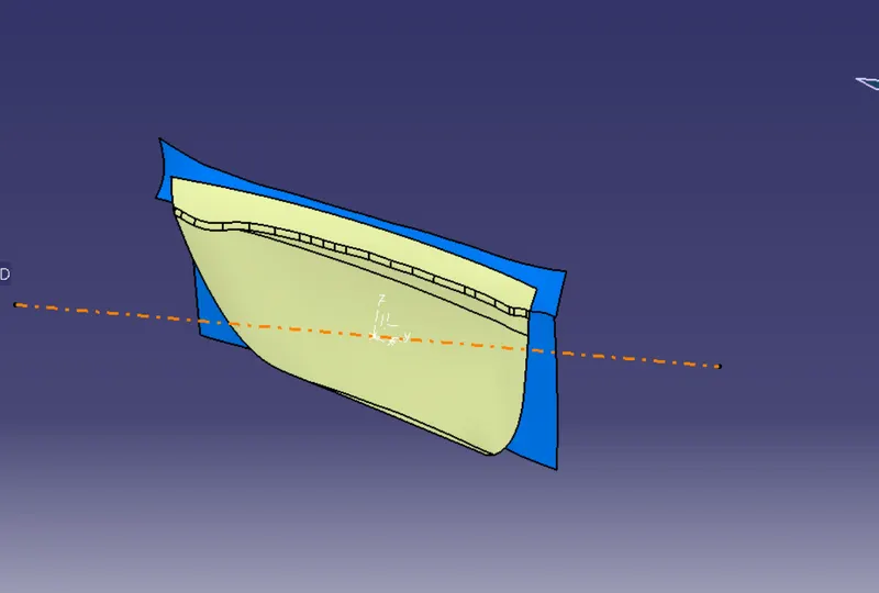
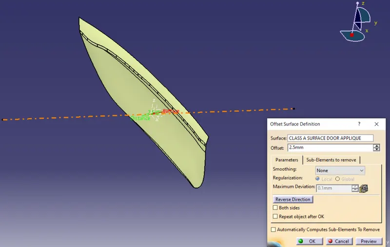
Class B surface for door applique:
I've created class B surface by offseting the class A around 2.5 mm
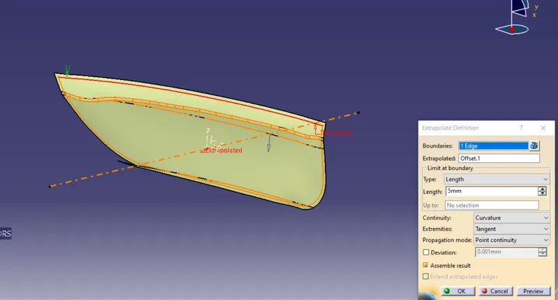
Class C surface creation:
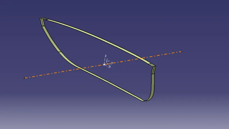
Then i created a sweep
Then i created extrapolate on class A and class B as well
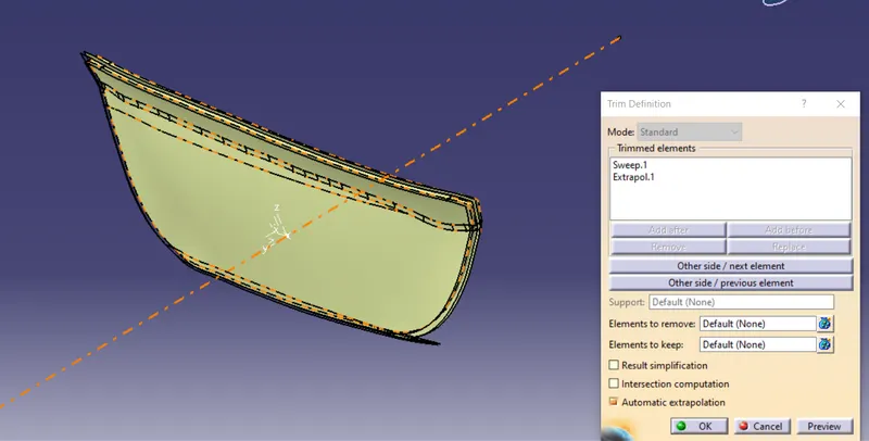
Then trimm them both separately
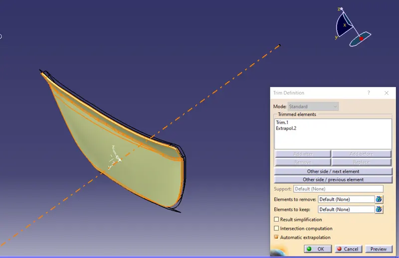
Eventually we've got a closed surface
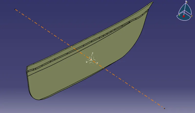
Then i've got a soild component
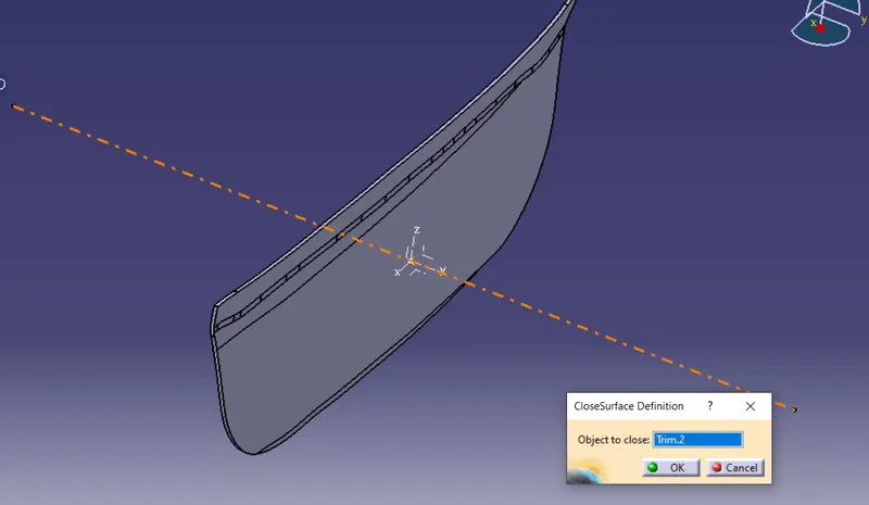
Creation of 4 way locators:
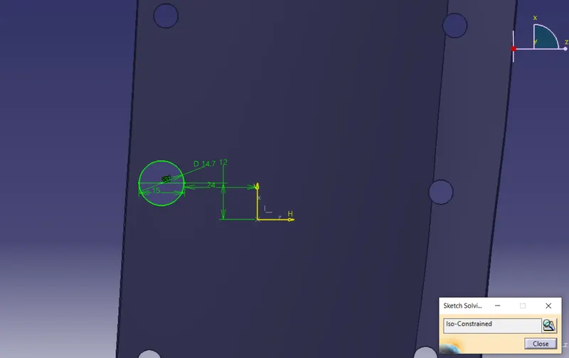
I drew a lines in 15 by 15
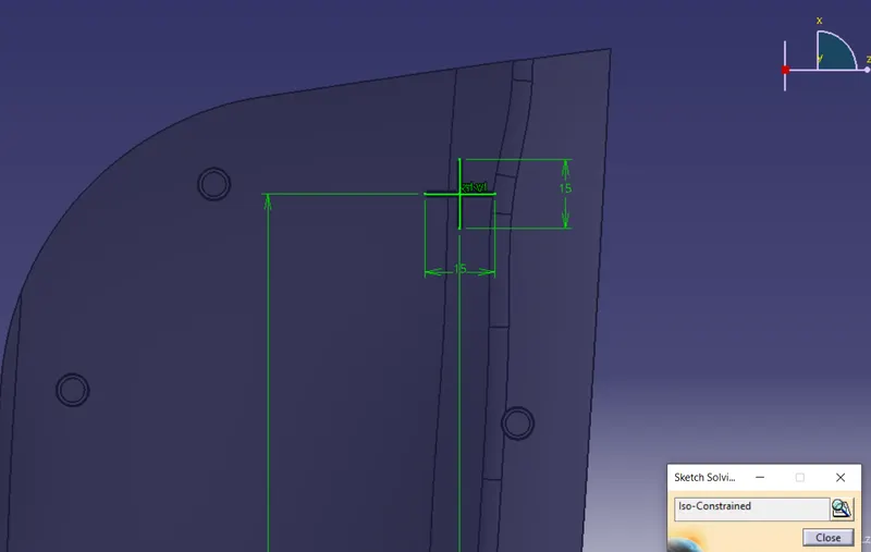
Then pad itself
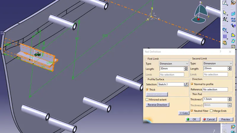
After all that i gave required amount of draft and fillets
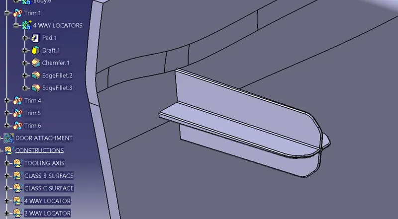
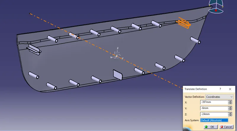
Then the other one i translated
And same way i followed for the two way locator as well
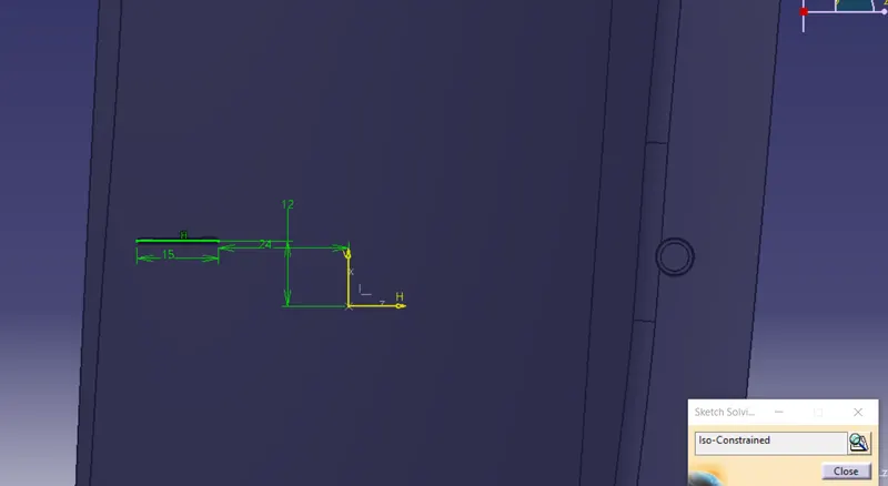
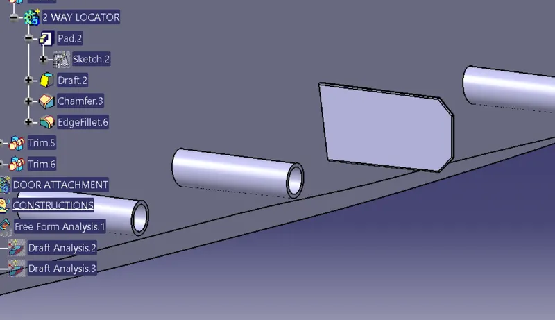
Creation of heatstakes:
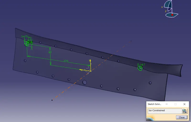
I drew a sketch for heat stakes
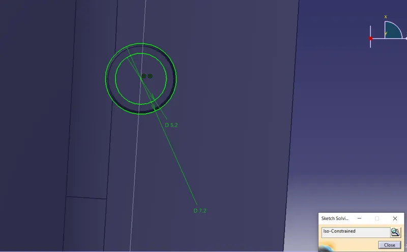
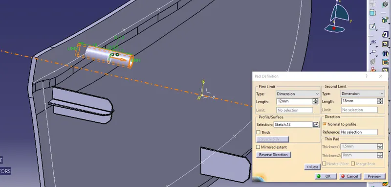
Then i pad it and i made user pattern on repetition points which are created on paralel curve
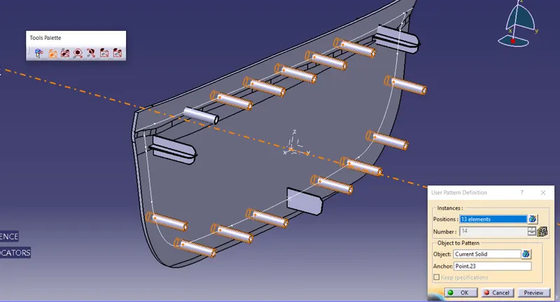
Eventually i did union trim with door applique part
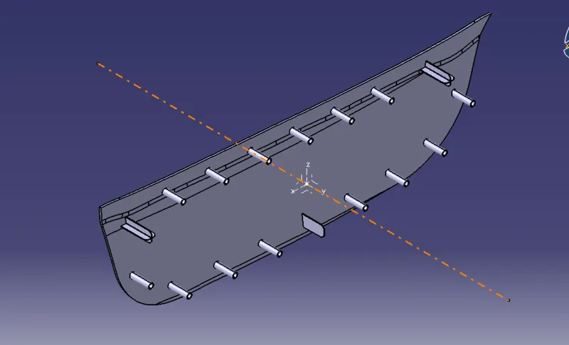
Door attachment surface:
I've given thichness of 2.5 mm to create a solid
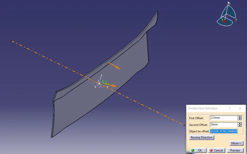
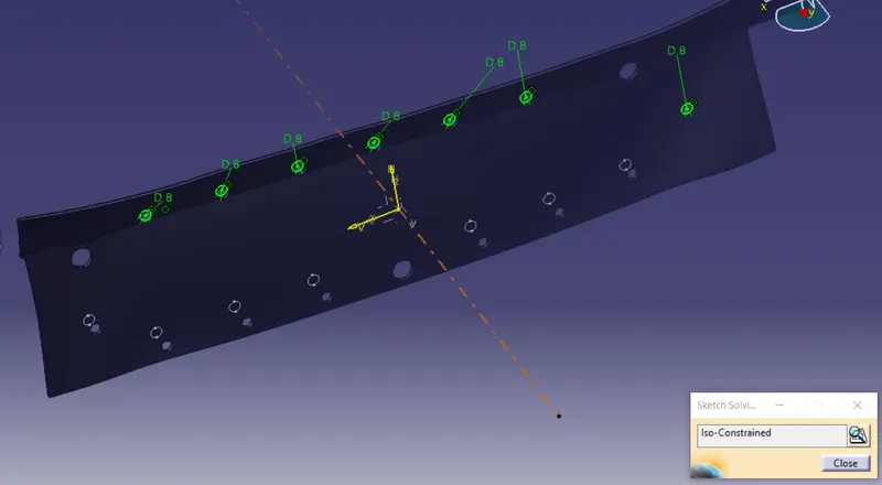
Clearence for engineering feautures:
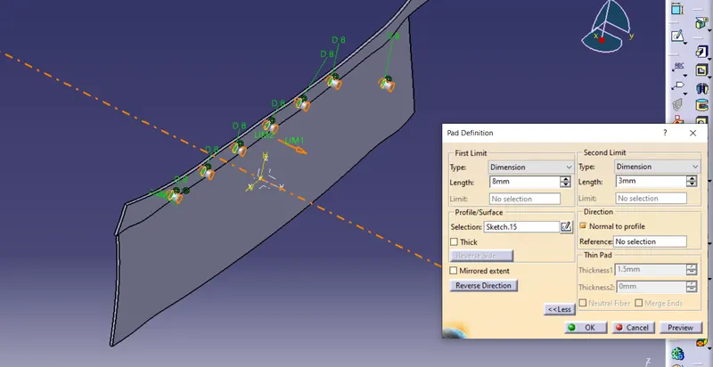
I make holes for give a clearence to heat stakes
Then i pad it
And same thing i done for the clearence for locators also
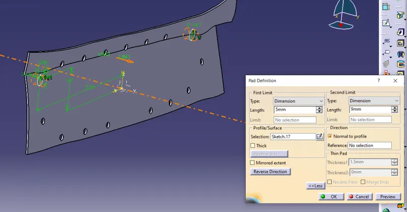
Then i removed the pad which i created with attachment surface
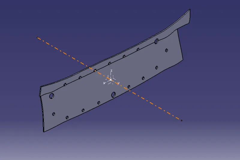
What is draft analysis:
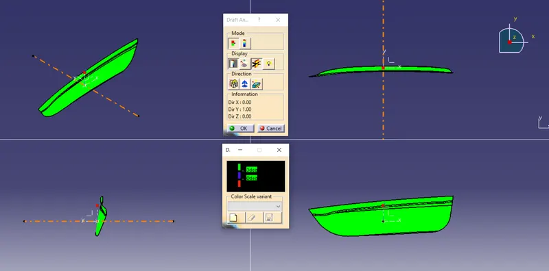
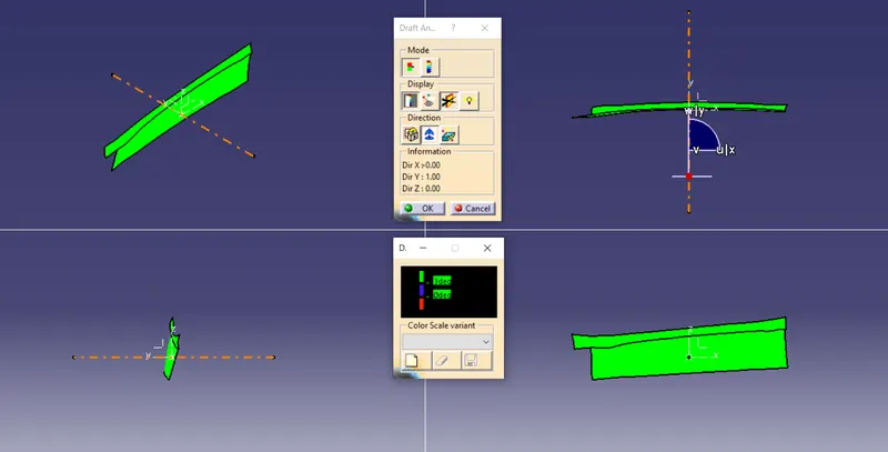
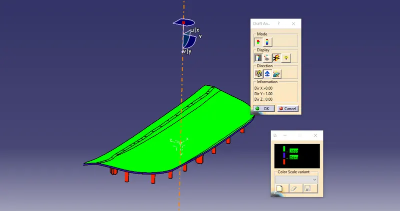
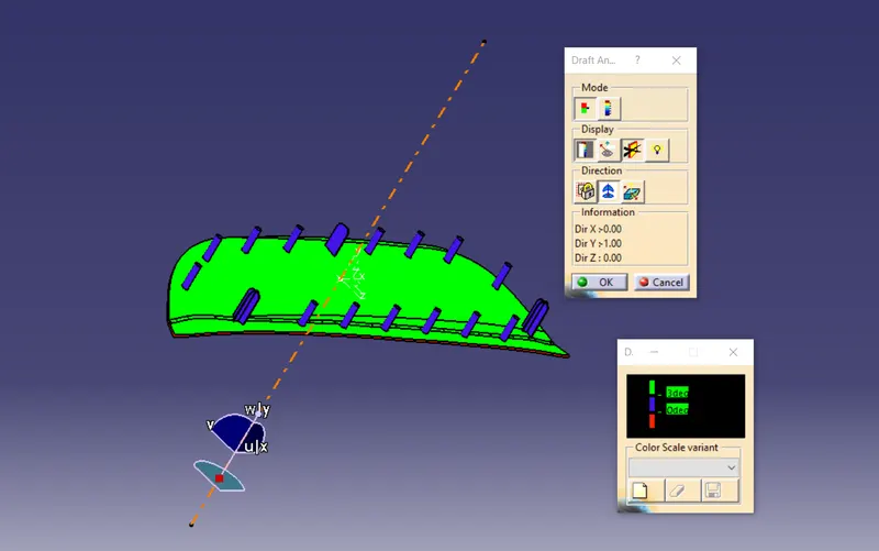
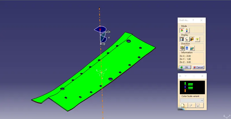
Draft analysis is a handy tool which allows to see there's a component or part if does it clear completly with tooling which means we can predetermind if the part can get ejected from the mold during the ejection process.
Creating the tooling axis:
Point direction method:
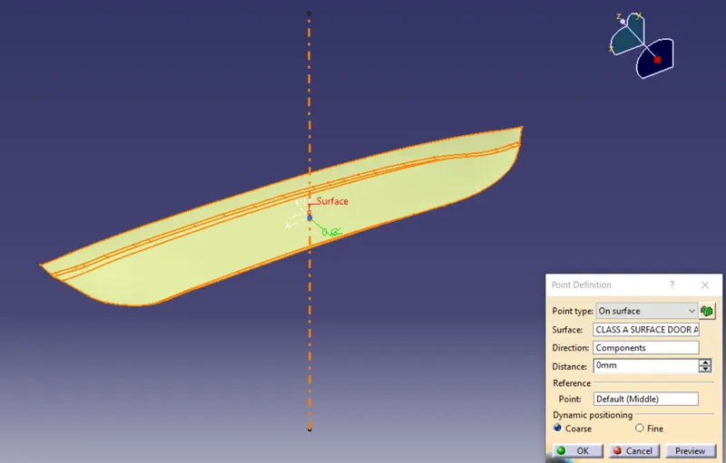
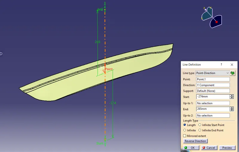
I've created point over the surface then i created the line along with Y component then that's gonna be as our tooling direction
Bisecting method:
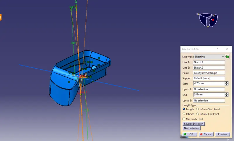
This one is slightly different from point direction method in this case we gotta create intersection on X and Y direction of component then create separate line at both edges of the intersections and create a line in bisecting method between those intersection, then eventually create a line in bisecting method between those two lines which are created at both intersections and that will be our tooling direction and it does can be with more accuracy compare with tooling axis created with point dirrection method.
(for refference)
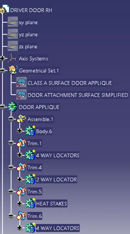
Tree structure of geometrical set:
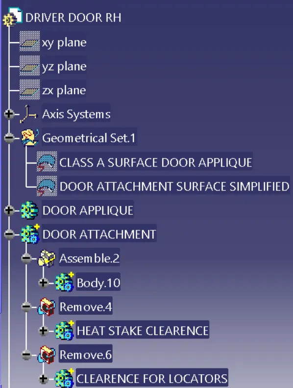
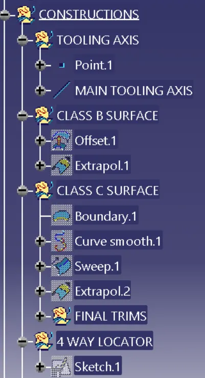
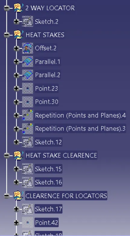
Draft analysis report on class A:
Draft analysis report on solid part:
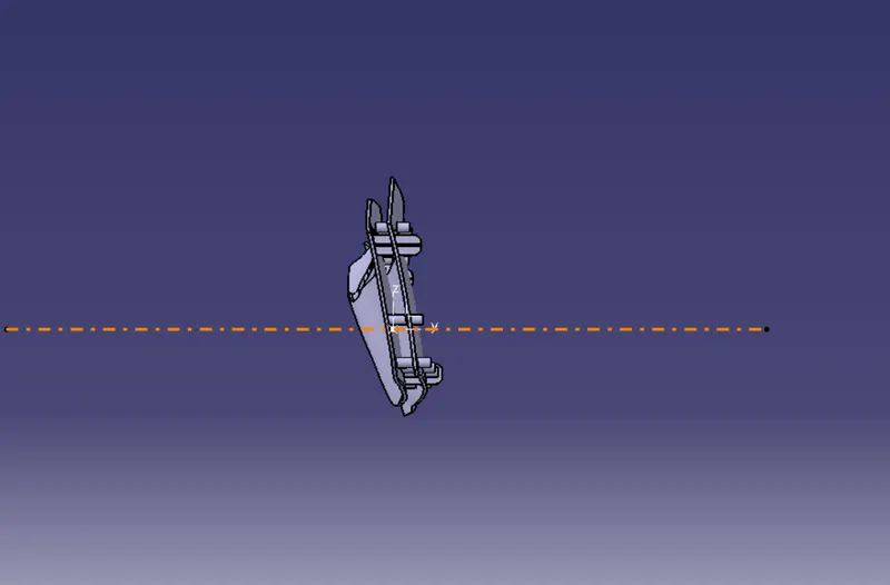
Front view:
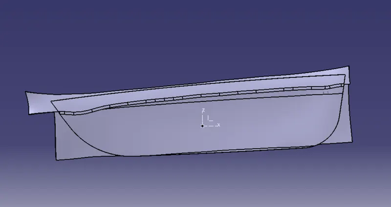
Left view:
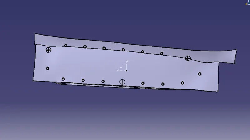
Right view:
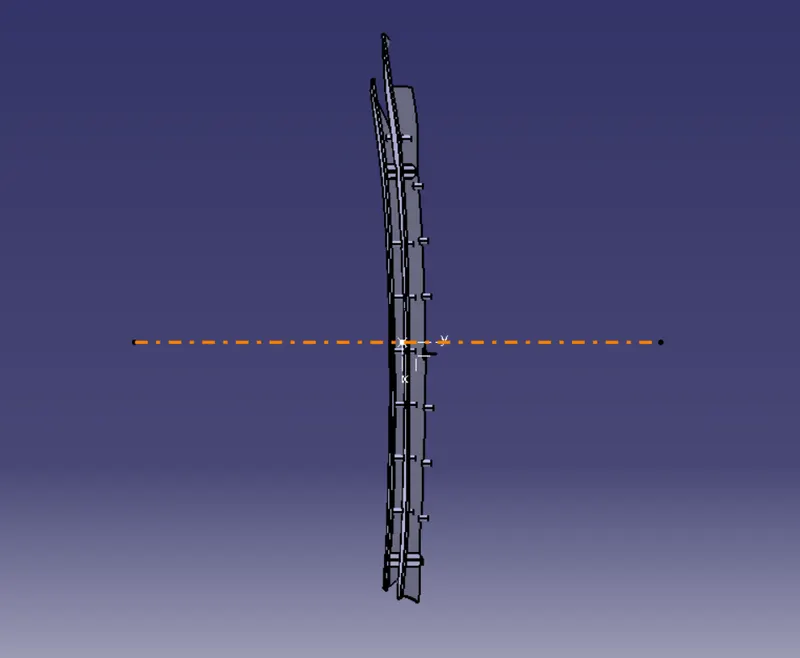
Top view:
ISO-metric view: