Week 9 - Project 1 - Door Applique Design with Engineering Features
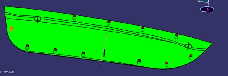
AIM: To Create the Base Bracket Plastic component through the given Class-A surface. To begin with, the tooling axis for the given Class-A Surface should be created meeting the requirements of the draft angle and at the end perform the Draft analysis on the model.
What is heat staking?
Described as a pulsed heat process used to join two or more parts out of which at least one is made of plastic, heat staking involves deforming the plastic material using heat and force at a set process time. The bond is made by partly de-forming the plastic part to fix the other. Therefore, the process makes it easy to bond metal to plastic, which is why it is commonly used in high volume/low-cost applications like automotive, IT and consumer appliances.
Procedure:
Tooling Axis creation:
First extract the base surface of class ‘A’ and on that create the point and then create Axis system at that point.
Create the tooling axis in Z direction.
This line is the Main tooling axis for the part.
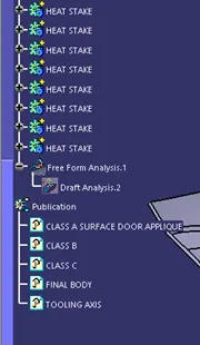
After which we will be publishing the tooling axis and class ‘A’ surface.
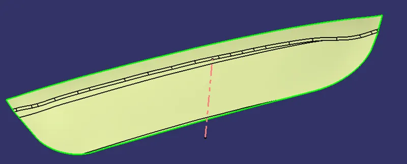
Draft Analysis of Class 'A',
Insert -> Analysis -> Feature Draft Analysis
Keep the view mode to material.
Drag the compass (Direction – compass) on the tooling axis and then select proper direction and lock it.
Giving draft angle as 3 degrees.
‘B’ Surface Creation:
Extract Class ‘A’ Surface.
Untrim extracted surfaces.
Extrapolate to some extent.
Use trim and select proper surface.
Offset inward at 2.5 mm
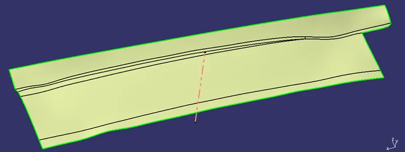
'C’ Surface Creation:
Take outer boundary using Boundary command of class ‘A’ surface
Use sweep command to create surface using tooling axis and draft angle as 3 degrees.
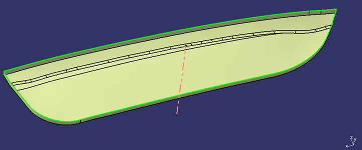
Final Body creation:
Join class ‘A’ surface and ‘C’ surface.
Trim resulting surface with ‘B’ surface.
Join the surface.
Result is complete close surface.
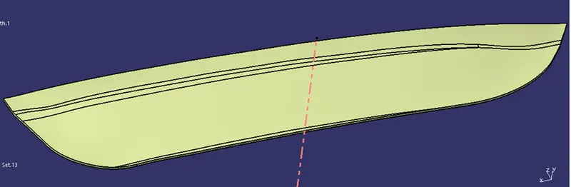
Solid Body:
Change to Part workbench.
Create Body.
Surface Base Feature – Close surface – select last join.
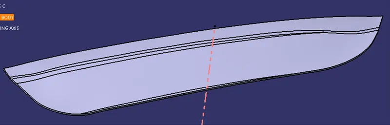
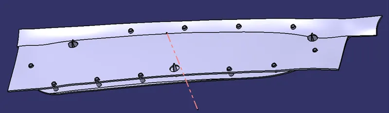
Door Attachment Feature
Give Thickness of 2.5 mm inside
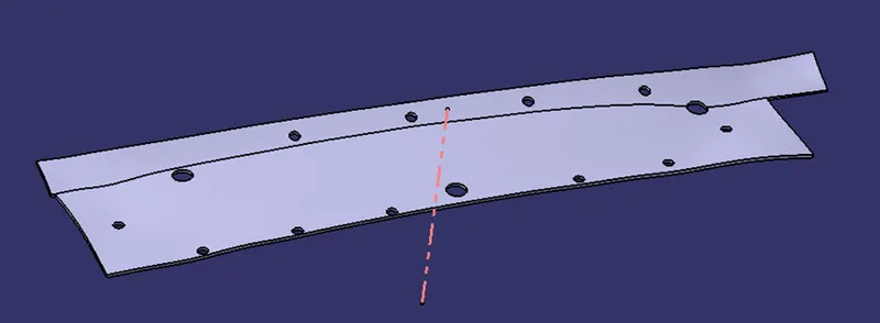
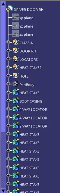
Locator Design,
Create sketch by taking door attachment class 'A' surface as reference.
Pad the sketch up to certain limit and use design rules as per Rib design.
Use 0.5-degree draft with pulling direction as tooling axis.
Give entry chamfer.
Give Fillet
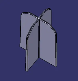
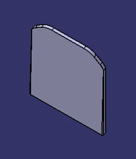
Union Trim with Door Applique.
Use Translate command for number of same locators
Heat Stakes Design,
First, extract the class 'A' boundary and use parallel curve command to offset the extracted curves.
Use point and plane repetition command for points on the curves.
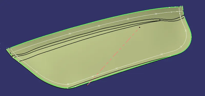
Create sketch by taking door attachment class 'A' surface as reference.
Pad the sketch up to certain limit and use design rules as per Screw boss design.
Use 0.5-degree draft with pulling direction as tooling axis.
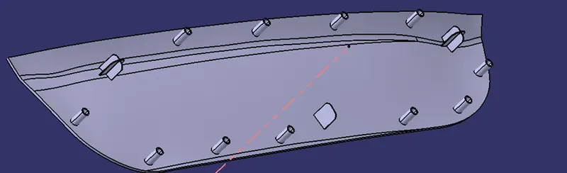
Give Fillet
Union Trim with Door Applique.
Use Translate command for number of same locators.
Counter cut-out holes on Door Attachments
Using same points as used for locator’s and heat stakes draw sketch of circle.
Pad It.
Give Draft of 0.5 degree
Remove from Door Attachment body
The gap for heat stakes is 0.5 mm and for Locators 0.1 mm

Draft Analysis: