Week 9 - Project 1 - Door Applique Design with Engineering Features
Door Applique with Engineering Features
OBJECTIVE-
Here we have to design the Door Applique part from the given Class A surface then also design it's engineering features(4way locators,2way locators,heat stakes)for fixing the designed part into some other part.
PROCESS
- So First of all we have to check the given part for any opening by performing the Boundary on the Class A Surface.
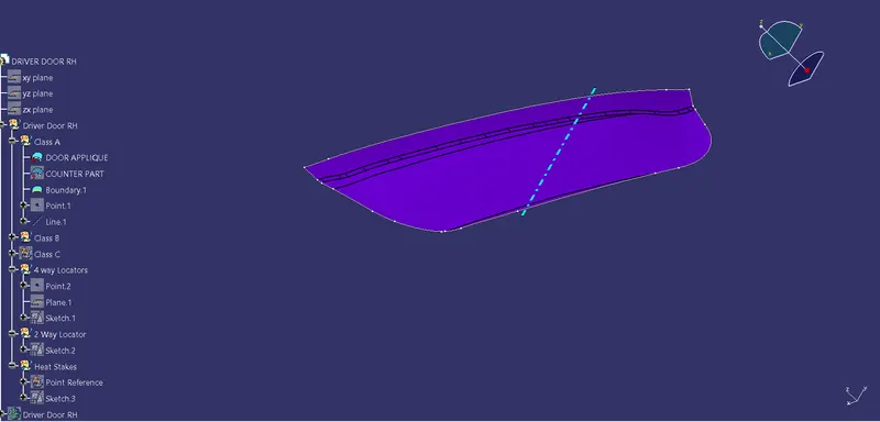
(Boundary operation on Class A of door applique )
- As here there is no opening so we can proceed further for creating the Class B.
- Now we have to design the Tooling axis for the given part to perform the Draft analysis.
- To design it we need to Create the Point on the surface which is create by default in the middle of the part.
- Then we have to create the Line with Point-direction option.
- Now the line we get is the Tooling Axis for us.
- Now we need to perform draft analysis in the class A to check any straight plane on the part.
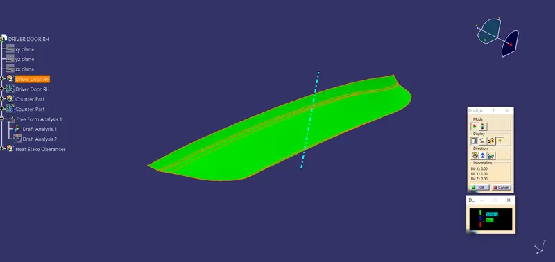
(Image for draft analysis)
As the Image shows the Green so we can proceed for creating the Class-B surface.
Here we can create the Class B by taking small small parts of Class A & extract them & alter them to get our desired part but here no need of that we can directly Select the Class A & Offset it 2.5mm & we get our Class B Surface.
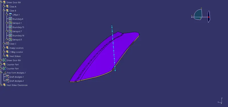
- Now we have to Proceed for creating the Class C of the part.
- For Creating that we need to separate the Class A into small small Boundary.
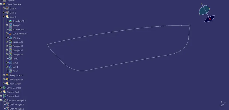
As we can see in the above picture the whole Class A is divided into 2 small small parts top Straight 1 & bottom curve.
Now we have to perform the sweep operation along the Tooling Axis.
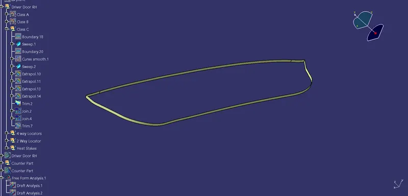
- Now We have to Join this 2 parts into single part to do that we need to Extrapolate the edges to certain amount & trim them from each other so that we dont have any gaps in the cornor & the part will not create any issues in the future.
- Now As the Class C is ready we have to join this with the Class A surface
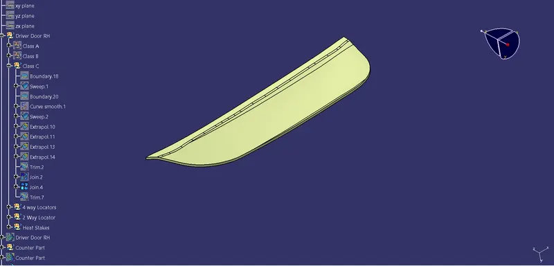
- Now we have to Trim this Created Class C & Class B to get our part.
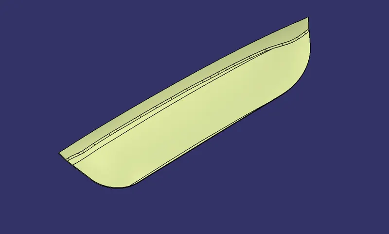
- Now to convert the generative shape design into part body we have to perform the Close Surface Operation .
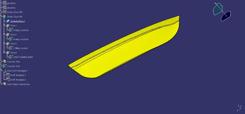
- This is the desired part that we need to create for Door Applique.
- As our part is ready so we can further proceed for creating the 4way locator.
4way locator-:This restricts 4 degrees of freedom along 2 axes.
- First of all we need to create a point on the surface of the created part.
- Then create a plane parallel to that point with reference to the ZX plane.
- Now create the Sketch in that plane.
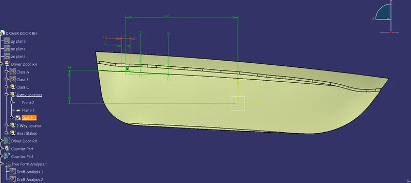
- Then insert a body & pad this sketch upto desired height.
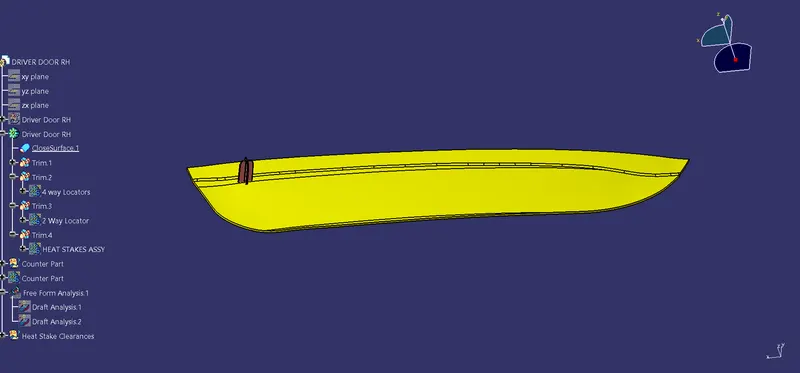
- Now we know that a 4 way locator will arrest 4 degrees of freedom but for this much big part need one more 4 way locator to properly fix the part into its respective counter part.
- To create 1 more 4way locator we have to copy the previously created 4way locator & select Paste Special----->As Result with Link.
- Then select Translate-------> Co-ordinates , apply the required Co-ordinates tom place the Another 4 way locator.
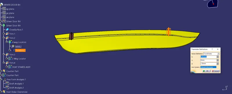
- As the part is ready we need to provide some alteration on the part (i;e draft on the part).
- Now as both the part created we need to join that parts to the main Driver Door.
- To do that we need to perform the Union Trim operation separatly.
- Now we have to create the 2 way locator on the part at suitable place.
Note:-Here these are the locators,so at the time of fixing locators will have the 1st contact to its other part.So the height of this part need to be same on the both side.
2way locator-: It restricts motion along 1 axis (or 2 degrees of Freedom).
Same way as that of 4 way locator we create the 2 way locator.
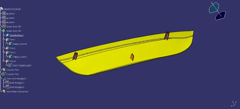
Now we have to make the Heat Stakes for this part.
Heat Stakes-:Heat staking also known as thermoplastic staking is the process of joining two dissimilar materials together.
For that perticular part we use the parallel curves option to create it.
- Now as our door is ready with the 4way locator & 2 way locator we proceed further for creating the Heat stakes.
- To do that we need to have the boundary of the created Driver door applique.
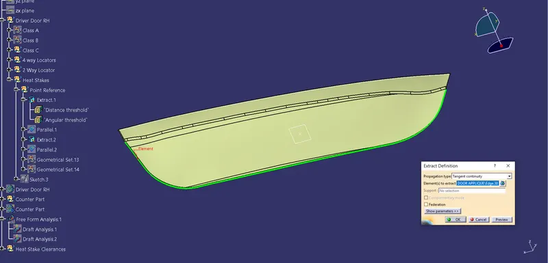
- Then other(top) side,
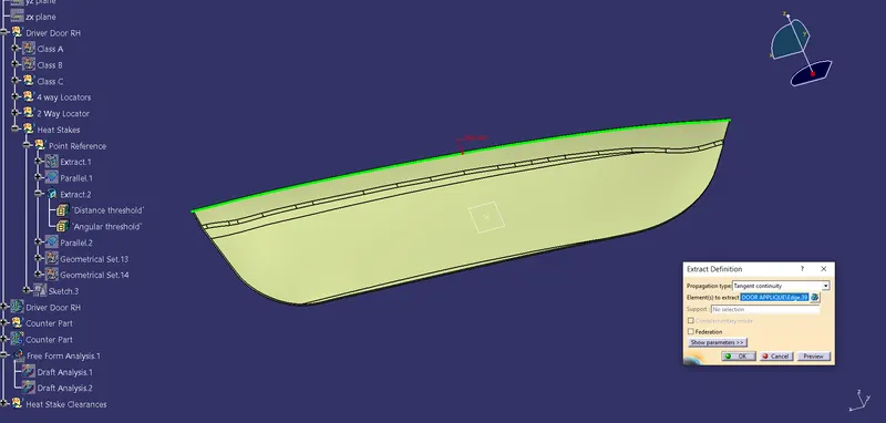
- Now we have to create parallel curves to these extracted curves of the part.
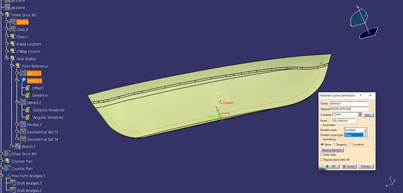
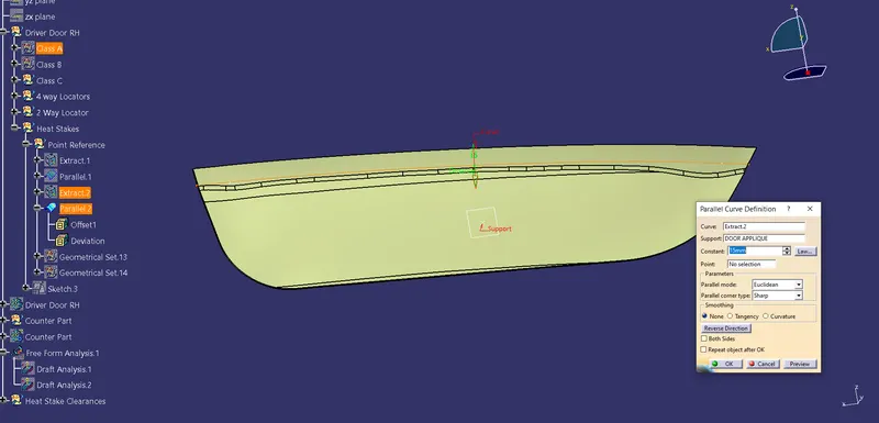
- Then we have to create some points on both of the curves.
- To create that ne need to perform the Point & plane repetition option .
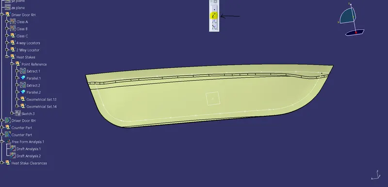
- Now as the points created we have to sketch the Heat Stakes on that perticular points.
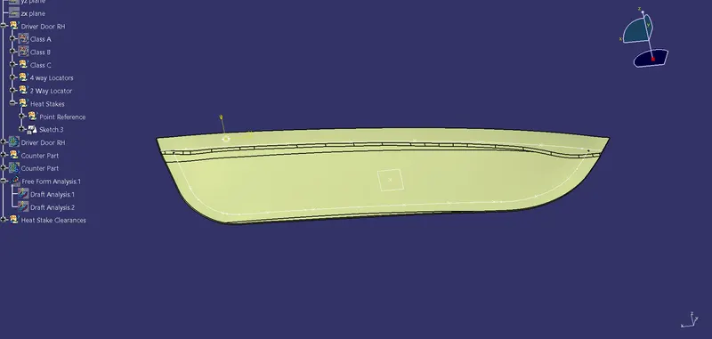
- Now Insert a part body & pad that sketch.
- Then apply DRAFT on the created part.
- Then we need to create same part on all the points on both the curves.To do that we need to COPY the part & select PASTE SPECIAL------------------>PASTE WITH LINK to get desired ITERATIONS.
- Then use Translate with POINTS Option to get the Iterations on the desired locations.
- Make Sure Heat stakes will not affect any other part on the body.
-
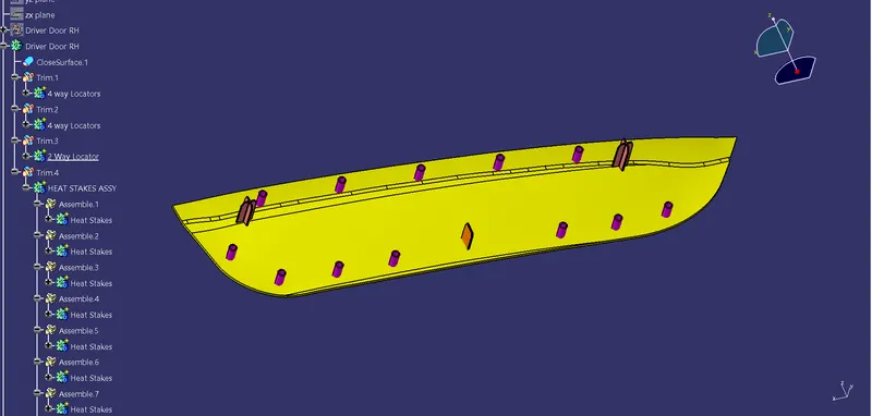
- Now make all the parts collected into one body & UNION TRIM that body with MAIN DRIVER DOOR.
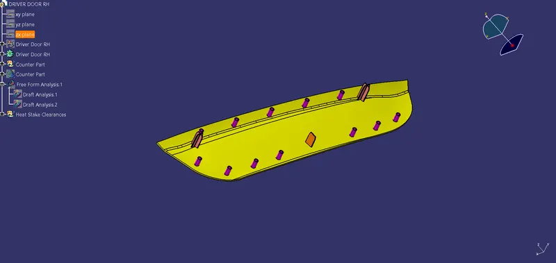
- Now the Main Driver Door Is Ready.Next we need to develop the Counter Part Class A into Part Body,to do that we need to follow the same steps as that of the steps for the DRIVER DOOR.(i;e-Offset Class A to get Class B ,then divided the Class A into small small segments for performing SWEEP operation along TOOLING AXIS)
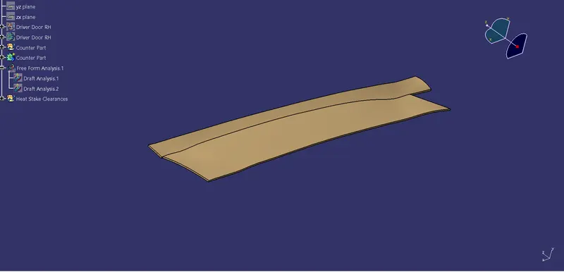
- The Counter Parts have the Clearances for the Parts(4way locator,2way locator & heat stakes) that we have on the Main Driver Door.
Note:-For Locators we need 0.2mm clearances & for Heat stakes we need 0.5mm Clearance.
- To Create the Clearance hole we need to EXTRACT the Sketch of the part.
- As we get the Sketch apply the 0.2mm clearance to it.
- Now Insert a part body & pad the Sketch.
- Then Remove the created part from the Counter part.
- Similarly we need to create the Clearances for all the 4way locator & 2way locator.
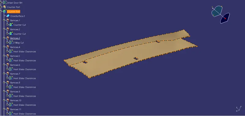
- Now we have to make the Clearances for the Heat Stakes that are presents on the Driver Door.
- To do that we have to Extract the sketch of the heat stakes & Apply Clearances to it & Make construction element to milddle circle.
- Now Insert a body & pad the Sketch.
- Then we need to Copy the part & Paste Special----------------->As Result with Link.
- Now REMOVE all the Bodies from Main Counter Part to have Clearances for the all the Heat stakes .
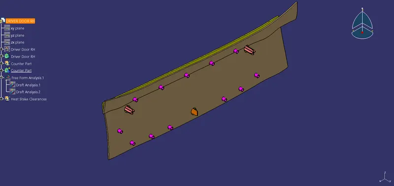
Above Picture shows the Driver door & its full setup for Fixiting the part.