Week 9 - Project 1 - Door Applique Design with Engineering Features
Title- Week 9 - Project 1 - Door Applique Design with Engineering Features
Objectives-
1. To understand requirements & functions of HEAT STAKES
2. To understand design guidelines for plastic products
3. To create class A, B & C surfaces
4. To create 4- & 2-way locator & Heat stakes
3-2-1 Principle (Arresting Degrees of Freedom)
Degrees of freedom in space
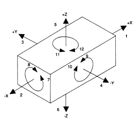 |
| Fig 1: The twelve degrees of freedom |
Degrees of freedom of rigid body-
 |
| Fig 2: A rigid body on a space |
 |
| _Fig 3: A rigid body on a plane |
- Resting - Stability
- Locating - W.r.t datum
- Orienting - W.r.t secondary datum
- Clamping - Ensuring above not disturbed.
Primary Locators
- Axial Movement downward along Z- axis (No.6 in Fig 2)
- Rotation about the X & Y axis (No. 7, 8, 9 & 10 in Fig 2)
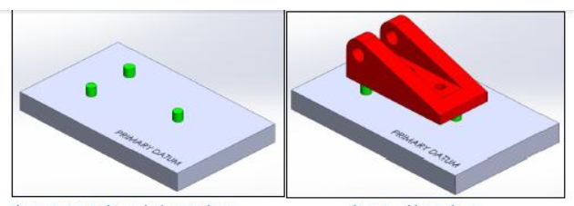 |
| Primary Locators |
Secondary Locators
- Axial movement along the Y+ axis (No.3 in Fig 2)
- Rotation about the Z axis (No. 11 & 12 in Fig 2)
 |
| Secondary Locators |
Tertiary Locator
- Axial movement along the X axis (No.2 in Fig 2)
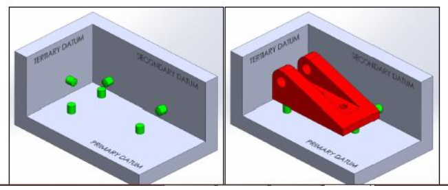 |
| Tertiary Locator |
Heat Stakes-
Heat staking also known as thermoplastic staking is the process of joining two dissimilar materials together. In heat staking we use local heating and cooling to raise the temperature of plastic components and allow plastic reforming to be carried out. This reforming can be used in a wide variety of applications.
Applications range from staking plastic bosses for assembly of car door panels to joining PCBs to plastic housings. Benefits of this technique include; no vibration damage, no particulates, the ability to stake metalized coated applications and the capability to stake in difficult to access or restricted areas.
Tooling axis creation-
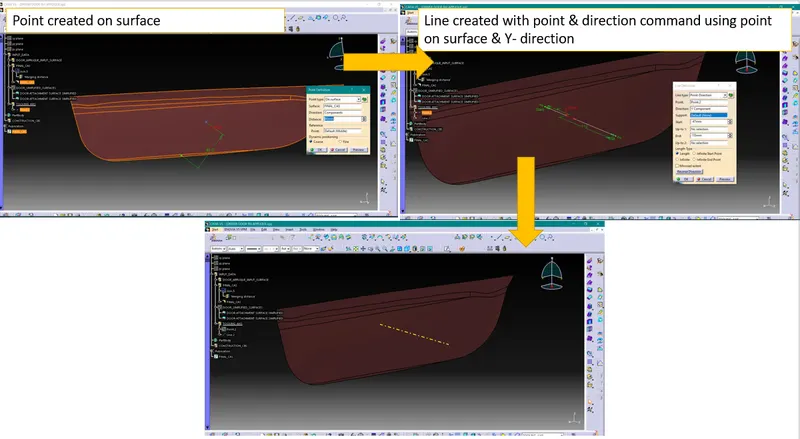
In this challenge we are going to create engineering features for the door applique component which do not having any complex geometry. So, we will create tooling axis along the direction which is normal to the component surface (Y- direction).
We have followed our standard process & created Main Tooling Axis as shown below-
Creating CAS (class A surface), CBS (class B surface) & CCS (class C surface)-
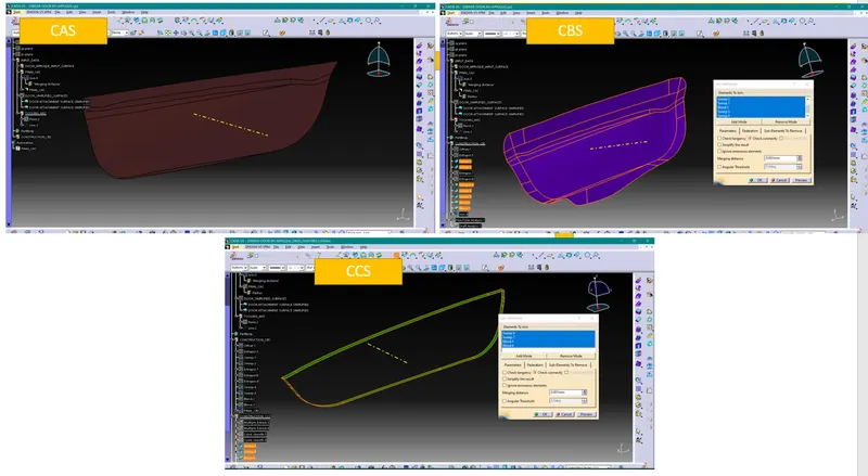
As input, we have CAS. Using this input surface, we have created CBS & CCS with our standard process
Close surface body-
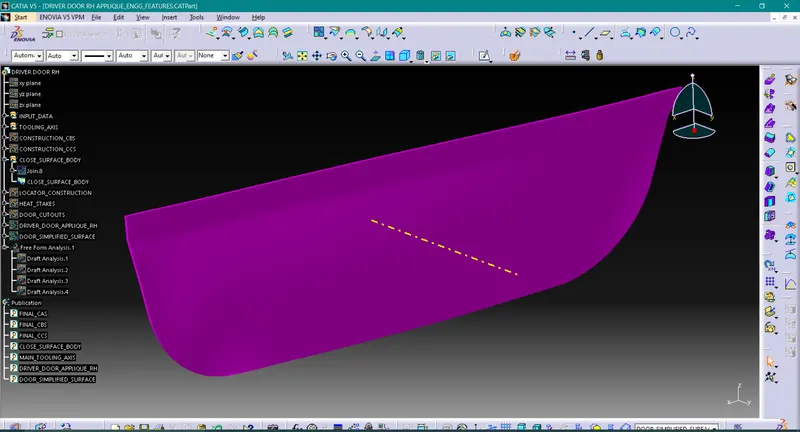
As we have obtained CAS, CBS & CCS, next we will create closed body with these surfaces using trim commands.
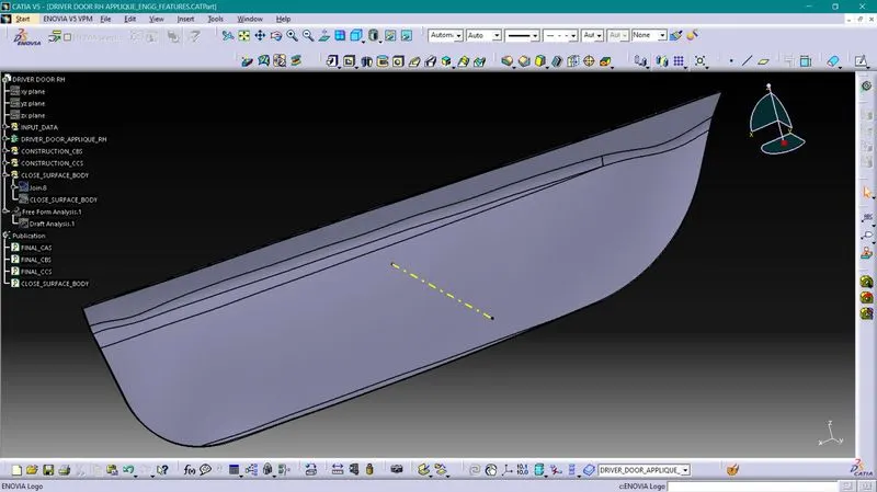
Using this closed surface body solid part body will be created
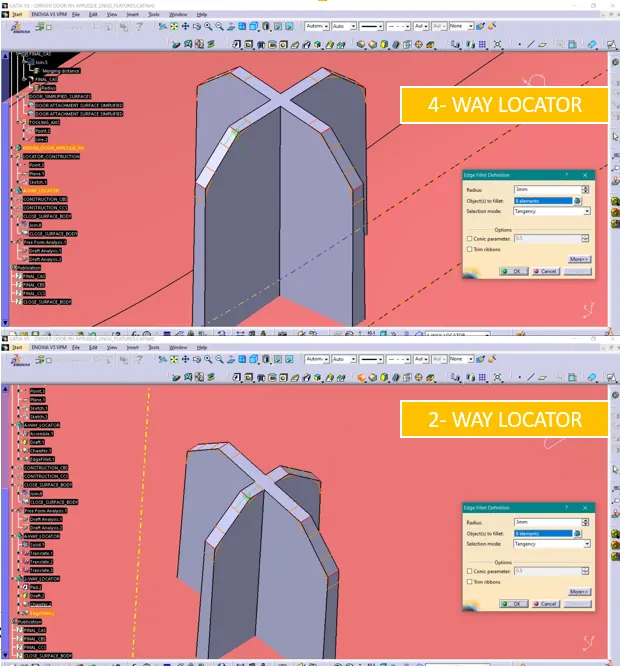
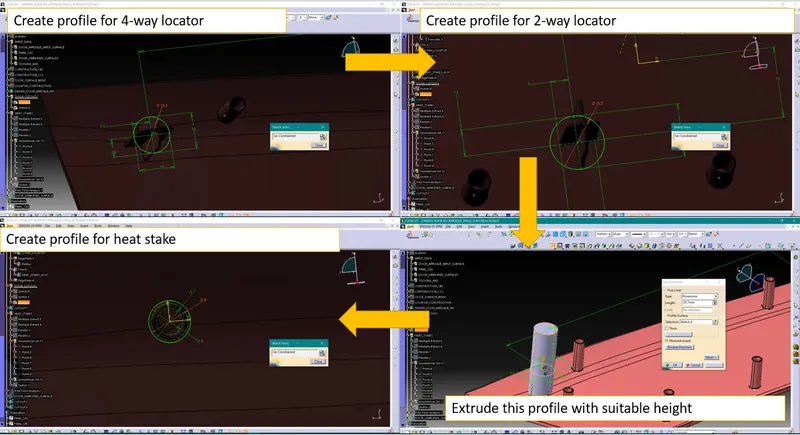
Creation of 4- way locator-
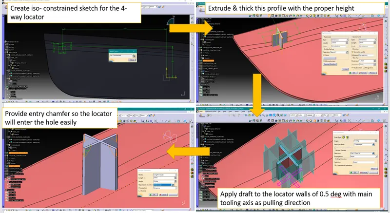
Make sure locator height will be higher enough that they will protrude above the locating hole.
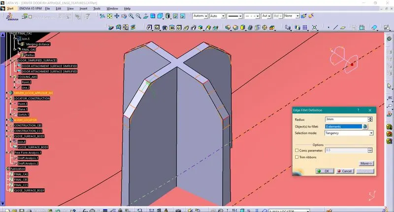
Apply suitable edge fillets.
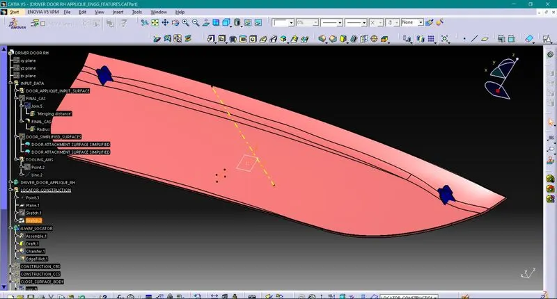
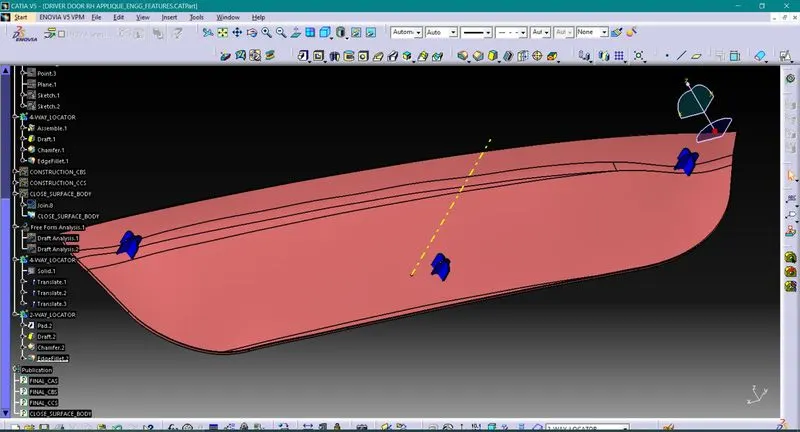
We will be creating 2 nos 4-way locators & 1 nos 2-way locator. All these three are will be placed in triangular shape.
2nd 4-way locator can be made by translating already made locator.
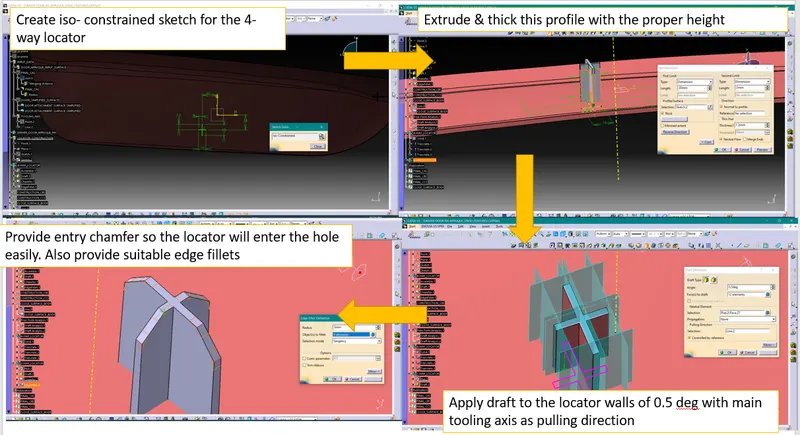
Creating 2-way locator-
Using union trim common join all the locutors with main component. After combining all locators give suitable edge fillets.
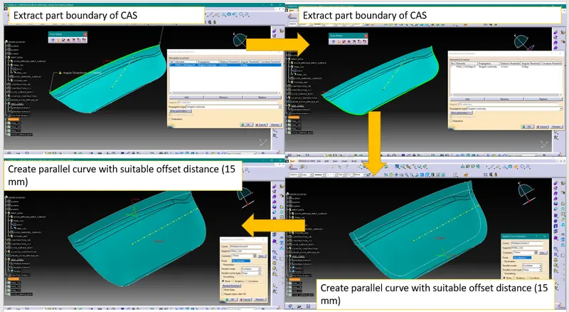
Creating Heat Stakes-
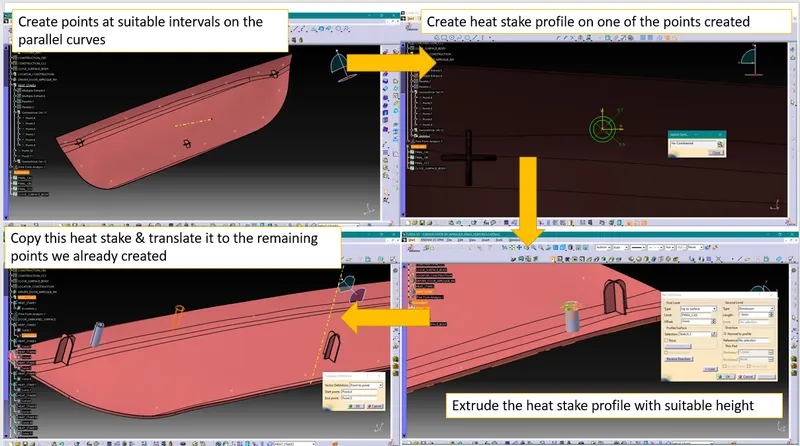
Make sure the height of the heat stake will be such that the will protrudes out of fixing surface but smaller than the locator. This is because at the time of locating, first locator should go inside the locating hole.
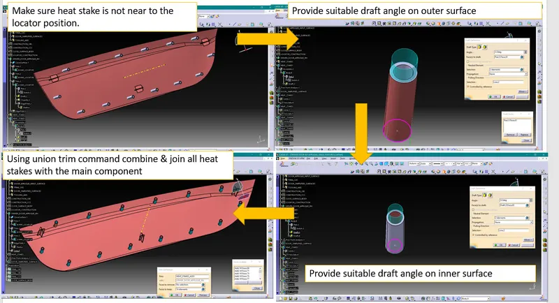
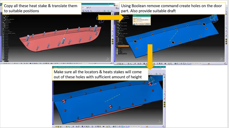
Making Holes on Door surface-
For the locators holes will be larger than the locator size by 0.1mm while for heat stakes holes will be larger than the heat stakes size by 1mm
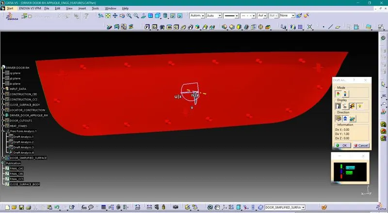
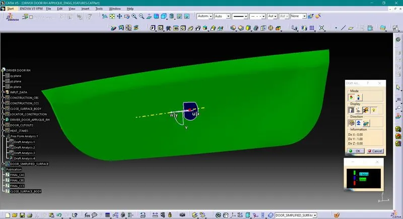
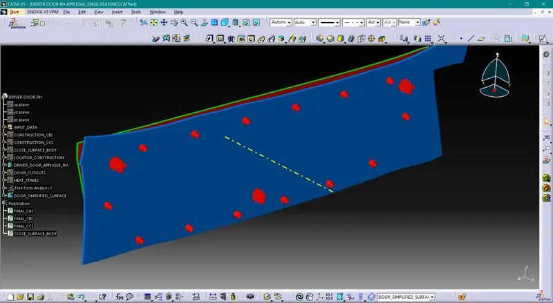
Draft analysis-
1. Draft analysis of CAS
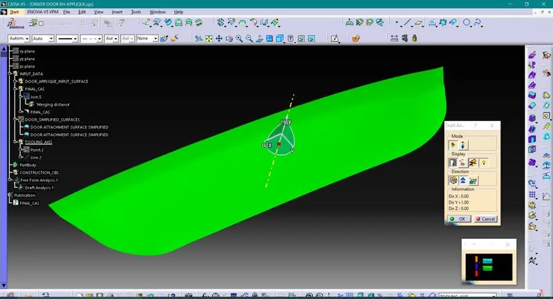
2. Draft analysis of part w/o engineering features-
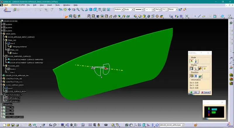
3. Draft analysis of locators & heat stakes with 0.5deg draft
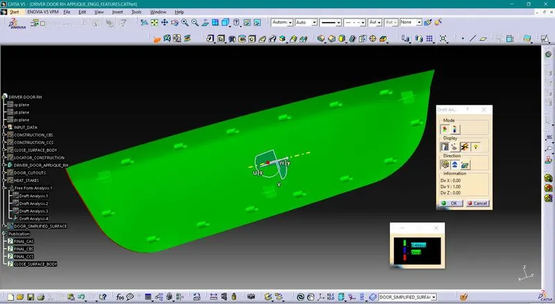
4. Draft analysis of complete part with 3deg
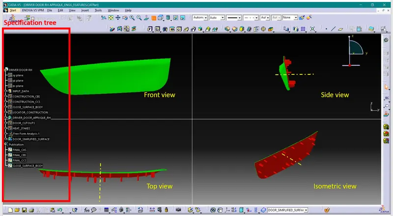
The completed design in various orientations-
Final View-
Conclusion-
1. We have understood requirements & functions of HEAT STAKES
2. We have understood design guidelines for plastic products
3. We have created class A, B & C surfaces
4. We have created 4- & 2-way locator & Heat stakes