Week 9 - Project 1 - Door Applique Design with Engineering Features
Door Applique Design with Engineering Features
Aim :
- Create Tooling Axis considering the required draft angle of a component.
- Perform draft analysis on the given Class-A Surface and then the final component.
- Create Class B and Class C Surface.
- Add the Heat stake and locators to the Door Applique trims.
- A detailed report based on the Draft analysis result and add the images required.
- Door Applique is an aesthetic part of the Door Trim.
- Engineering Features such as Locators and Heat Stakes help such parts fix on the door panel, by constraining all degrees of freedom.
Tooling Axis Creation
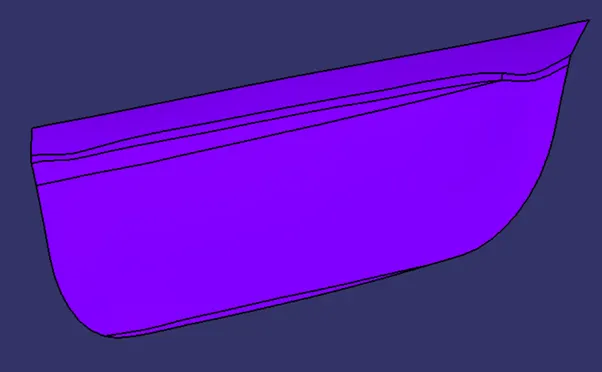
Figure: Given Class A Surface
Extract Surface from Class A Surface
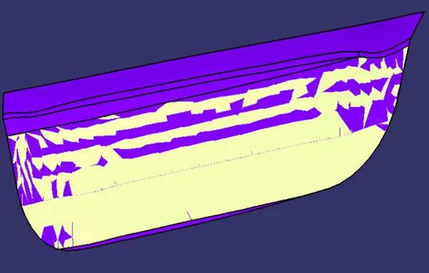
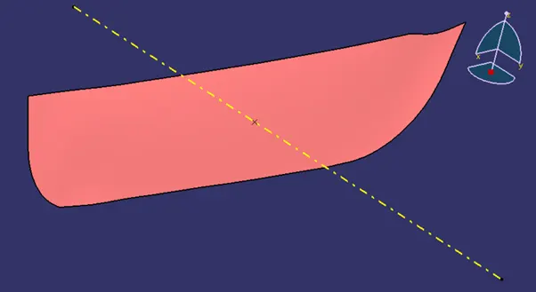
- Create a point on the surface and Construct a line along with Y-axis
- This Line will be considered as Main Tooling Axis
Draft Analysis of Class A surface
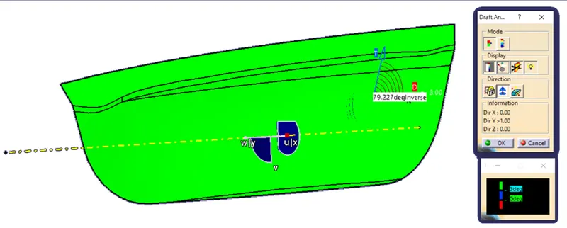
- Class A Surface complies with the minimum draft angle of 3 degrees.
- The product can be manufactured using the given Class A Surace and Tooling Axis.
Class B Surface creation
- Take extract from Class A Surface, excluding fillets.
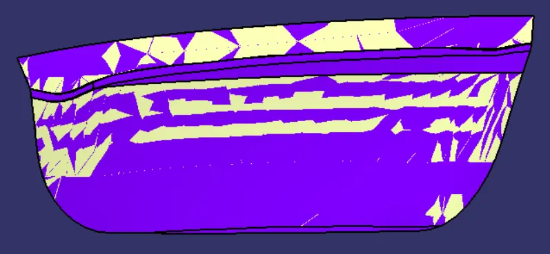
- Offset extracted surface to the thickness of part (2.5mm).
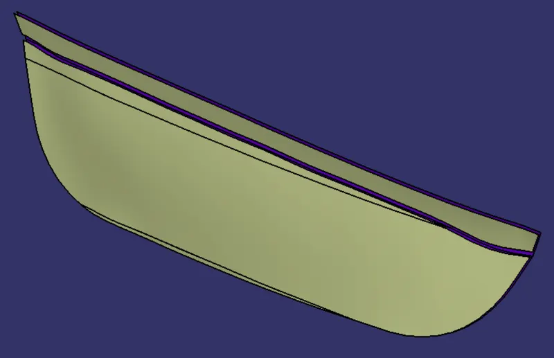
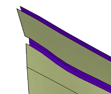
- Join surfaces that are adjacent to each other.
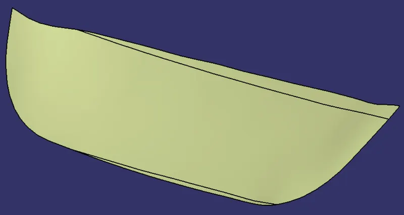
- By using extrapolate command extend both edges, and trim them together.
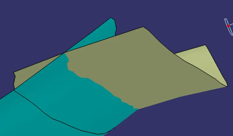
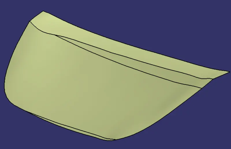
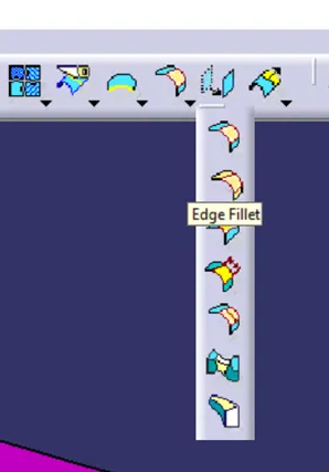
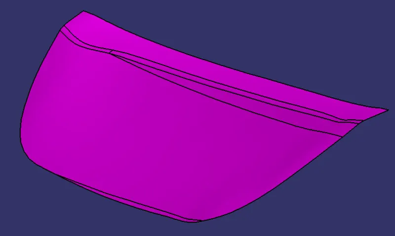
- Now apply fillet to a sharp edge, using the edge fillet command.
Class C surface Creation
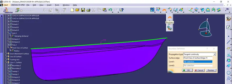
- Create boundaries along the edge of the Class A surface using tangent propagation.
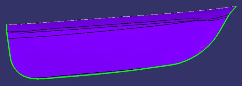
Sweep extracted edges along the Tooling axis
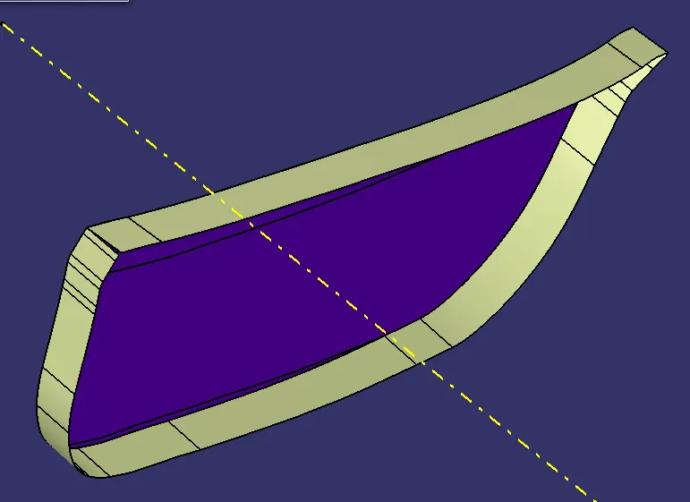
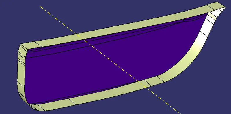
Trim both sweeped surface to form Final Class C surface
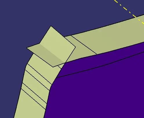
Before trimming make sure all surfaces are sutable for trimming
Image below represents surfaces which cannot be trimmed,
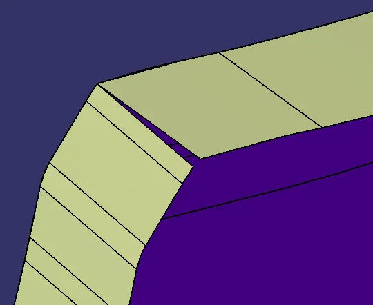
hence we need to extrapolate them and then trim them together.
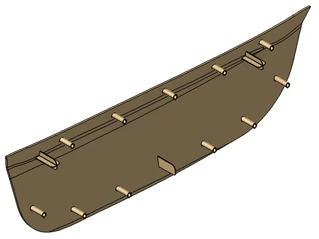
Images of Final Product
Isometric View without Door Panel:
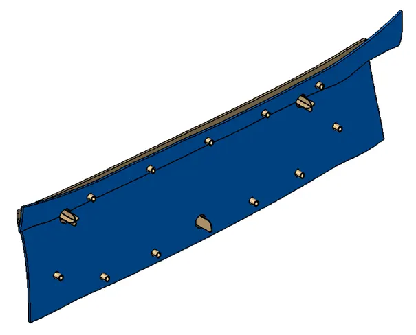
Isometric View with Door Panel:
- The clearance gap between Locators should be 0.1mm
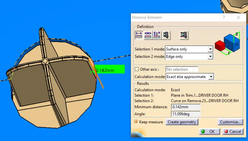
Figure: Gap Between 4-Way Locator and Dorr Panel
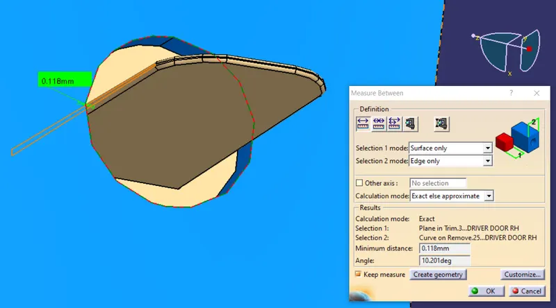
Figure: Gap Between 4-Way Locator and Dorr Panel
- The clearance gap between Heat Stakes should be 0.5mm
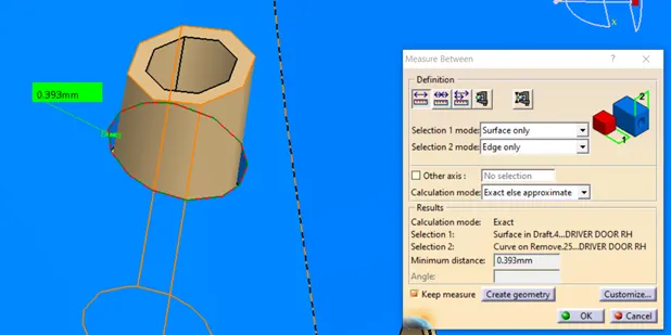
Figure: Gap Between Heat Stake and Dorr Panel
Front View:
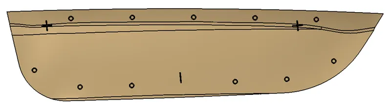
Side View:
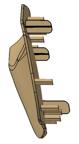
Top View:

Draft Analysis of Door Applique
- The nominal Draft angle for any plastic component is 3 Degrees.
- Door Applique made with the help of given Class-A Surface has a minimum draft of 73.51 degrees.
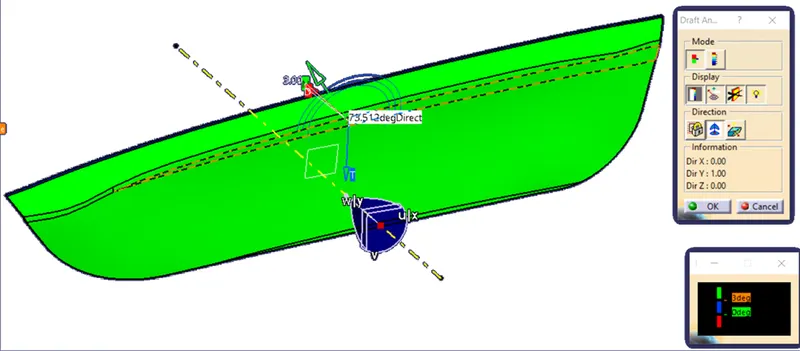
Figure: Door Applique Draft analysis -1
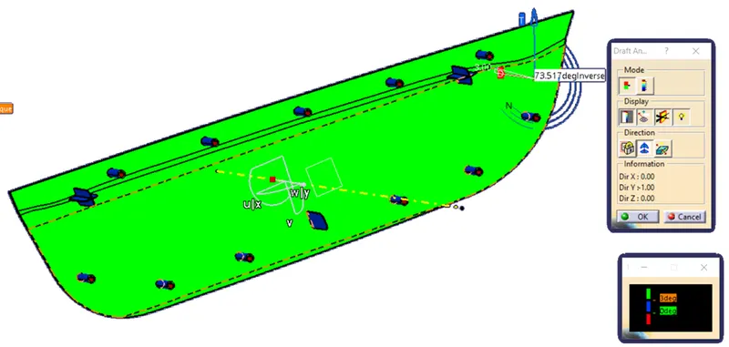
Figure: Door Applique Draft analysis -2
- Engineering Features should have a minimum draft of 0.5 degress.
- 4-Way Locator, 2-Way Locator, and Heat steak Have a minimum Draft of 0.5 Degrees.
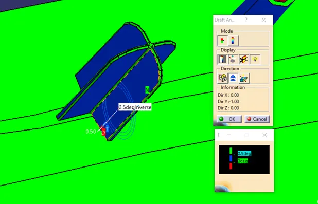
Figure: 4-Way Locator Draft Analysis -1
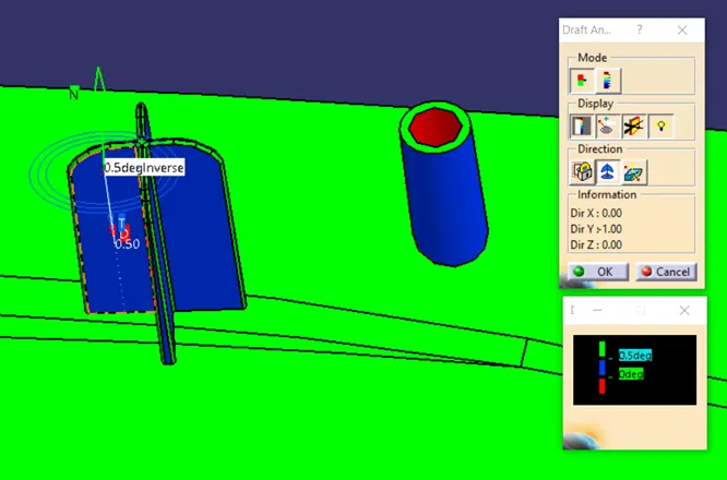
Figure: 4-Way Locator Draft Analysis -2
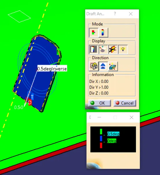
Figure: 2-Way Locator Draft Analysis -2
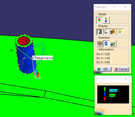
Figure: Heat Steak Draft Analysis