Week 9 - Project 1 - Door Applique Design with Engineering Features
AIM
To create heat stakes and locators on the required model
Performed Activities
Creation of Class B Surface
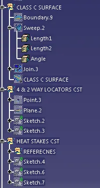
Creation of Class C surface
Creation of Heat stakes
Creation of Locators
Performing Draft Analysis
Procedure
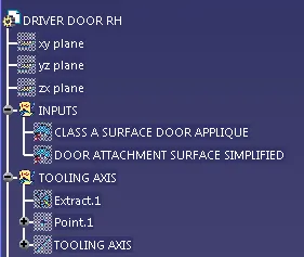
Tooling Axis
The tool axis is normally taken as Y-axis which can clear the model
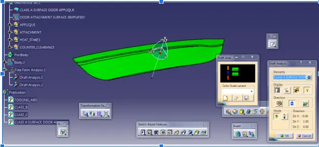
Draft Analysis
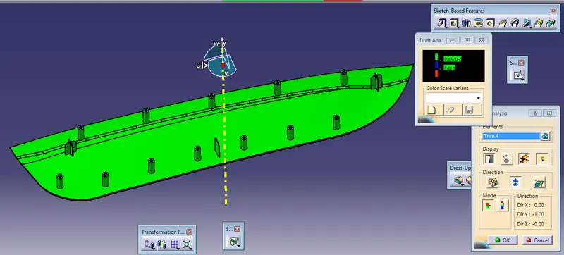
To Perform Draft Analysis On Class A Surface Initiate With The Draft Analysis
To Give Draft Direction Select The Compass And Align It On The Tooling Direction
Once After The Alignment Select The Class-a Surface And Select
The Surface Of The Model Will Show Us The Draft Angle
Green Colour = 3 Degree And More Than 3 Of Draft Angle
Blue Colour = Draft Angle Between 0 To 3 Degree
Red Colour = Draft Value Is Negative Object Fails
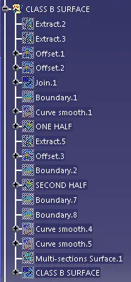
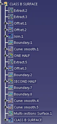
CREATING OF B SURFACE
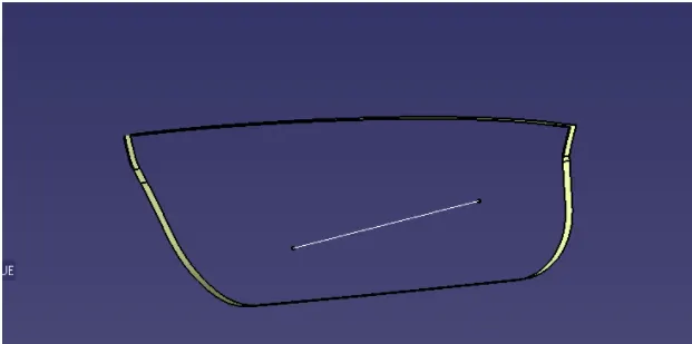
On the consideration of 2.5 mm of thickness, we are offsetting the CLASS A Surface by 2.5mm which is extrapolated to meet up the requirements
CREATING C SURFACE
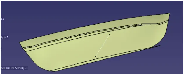
The Boundary of Class A has been extracted and sweep for 3 degrees with respect to the tooling axis which is objected to form the c surface
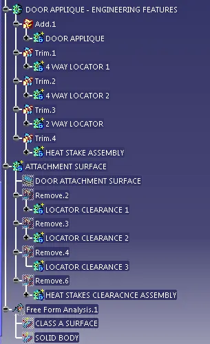
CREATION OF ENGINEERING FEATURES
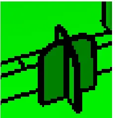
We have used different types of engineering features over here
- 4-way Locator
- 2-way Locator
- Heat stakes
Design Rule of 4-way Locator
THICKNESS = 0.4 * Thickness
DRAFT = 0.3 to 0.5 degrees can be given
FILLET = 0.3 to 0.5
HEAT STAKES RIB DESIGN RULE
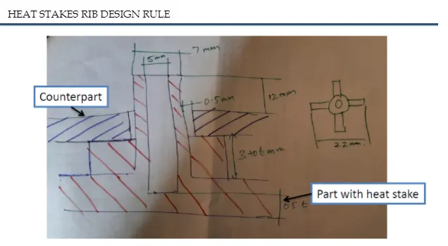
RIB THICKNESS=0.4*t DRAFT ANGLE= 0.5 DEGREE FILLET=0.5 OF RADIUS
DRAFT ANALYSIS OF CLASS A SURFACE
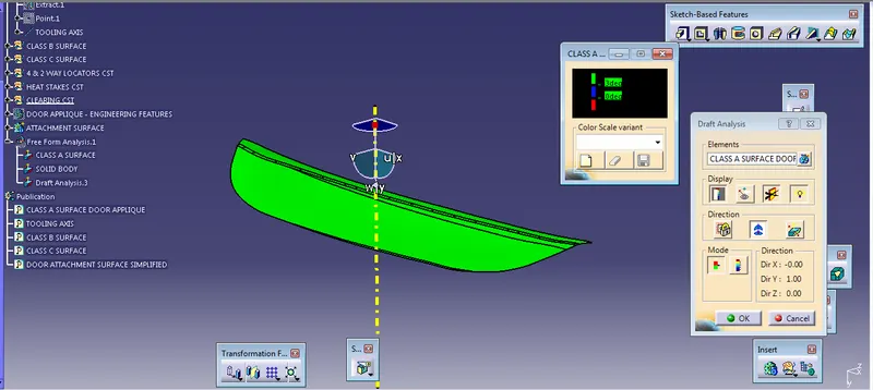
THE TOOLING AXIS HAS CLEARED THE PRODUCT BY 3 DEGREE OF DRAFT
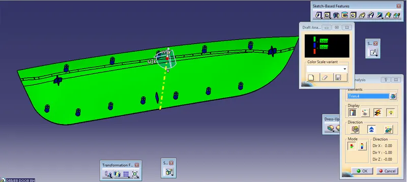
DRAFT ANALYSIS WITH ENGINEERING FEATURE
DRAFT ANALYSIS ON .45 DEGREE