Week 9 - Project 1 - Door Applique Design with Engineering Features
Iso Constrained Sketch
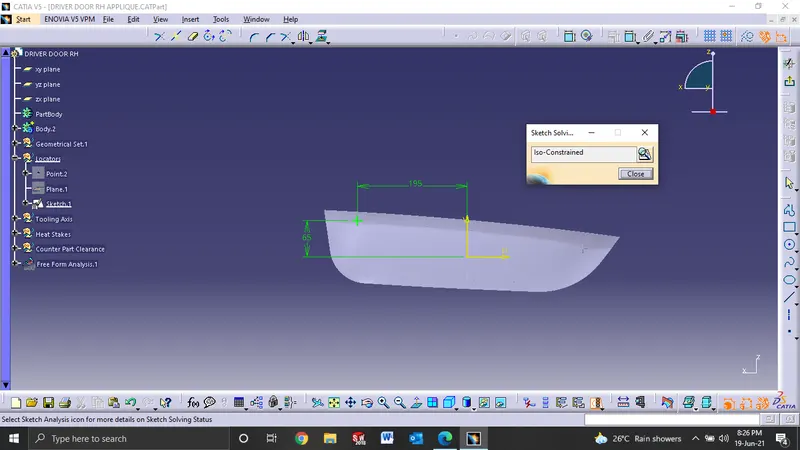
Draft Analysis Class A
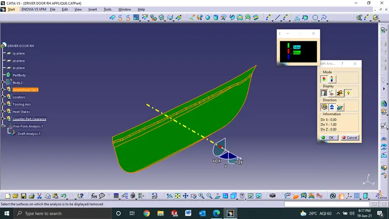
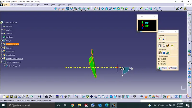
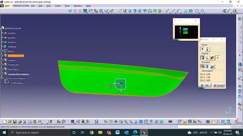
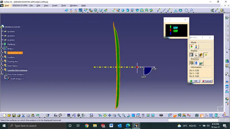
Draft Analysis Final Design
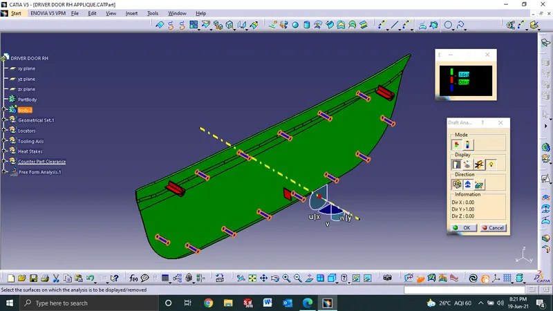
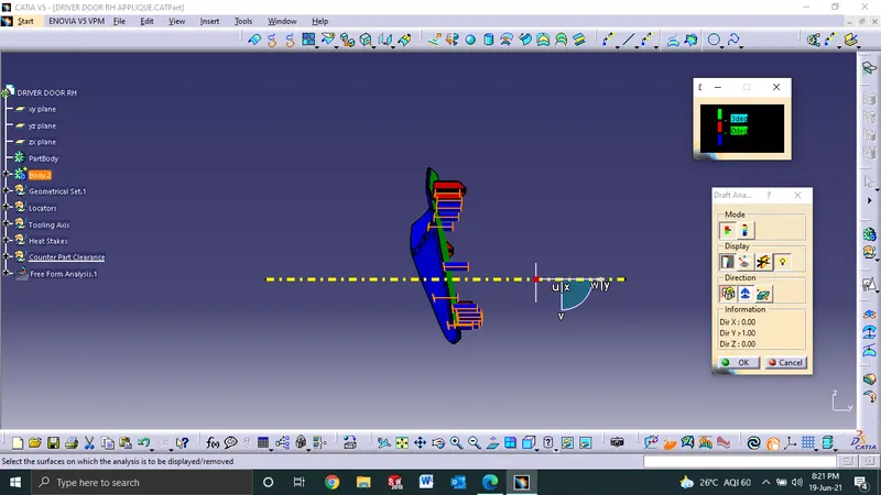
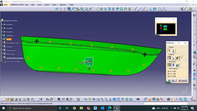
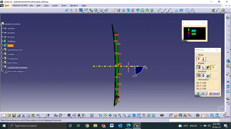
Final Design
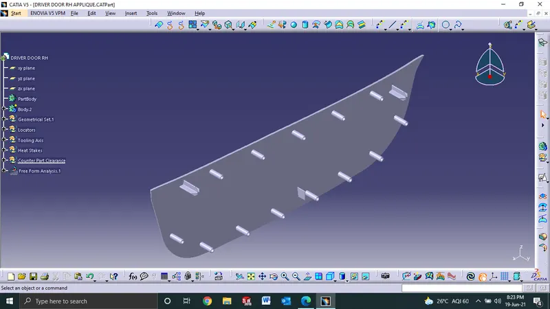
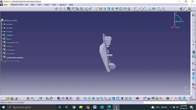
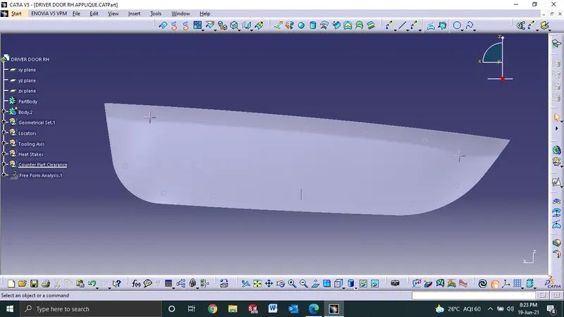
Tooling Axis Creation
- Firstly, two line are drawn taking the side edges of the class A surface as reference lines.
- The we take a reference point on the surface of the class A.
- Chossing the bisecting line option for creating a line we bisect the parallel lines that we created earlier along the reference point taken.
- Now for the draft to be possible in the direction of the class A surface, we take another line perpendicular to the bisected line passing through the reference point.
- This line so created is our Tooling axis and is demarcated in yellow.
Draft Analysis
-The draft analysis of the class A surface is done along the Tooling Axis created.
-It appears green and within the prescribed limits
-The draft analysis of the final body witht he locators and heat steaks are also performed along the Tooling Axis.
-The draft so created gives the colour indications and prescribed limits of the draft on the final product.