Week 9 - Parametric study on Gate valve.
OBJECTIVES
1) To carry out parametric analysis on gate valve system.
2) Study the change in mass flow rate.
3) calculation of flow coefficient and flow factor.
INTRODUCTION TO GATE VALVE
A gate valve is a device which is generally used to completely shut off fluid flow or, provide full flow in a pipeline when it is fully open. It is generally not used to regulate the flow because operating it in a partial open condition causes the gate to vibrate and chatter, which damages the seating surfaces and prevent a tight seal. At higher pressures, friction can become the problem.
CONSTRUCTION AND WORKING
A Gate valve typically comprises of following components: -
Body, Bonnet, seat and disc, spindle, gland and a wheel for operating the valve.
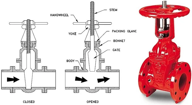
The primary operation mechanism is straight forward. Turning the handwheel rotates the stem, which moves the gate up or down via the threads. They require more than one 360° turn to fully open/close the valve. Lifting the gate from the path of the flow, the valve opens. Lowering the gate to its closed position seals the bore resulting in a full closure of the valve.
TYPES OF GATE VALVES
Screwed Bonnet
Bolted Bonnet
Welded Bonnet
Solid taper wedge disk
Flexible Wedge disk
Non-Rising stem type
APPLICATIONS
Gate valves have application in almost all fluid services such as fuel gas, feedwater, air, steam, hydrocarbon etc.
PARAMETRIC ANALYSIS
A Parametric analysis is the study of the influence of different geometric or physical parameters or both on the solution of the problem. This type of analysis helps to find the optimum design configuration for the best results with less computational time and cost.
In the present study the gate disc lift has been parameterized and change in mass flow rate has been observed for corresponding design points.
GEOMETRY
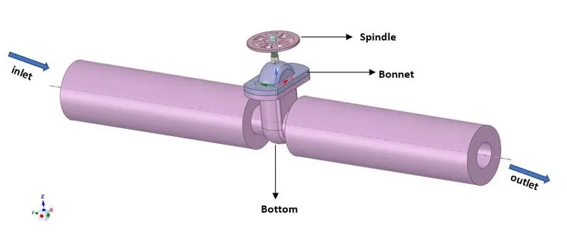
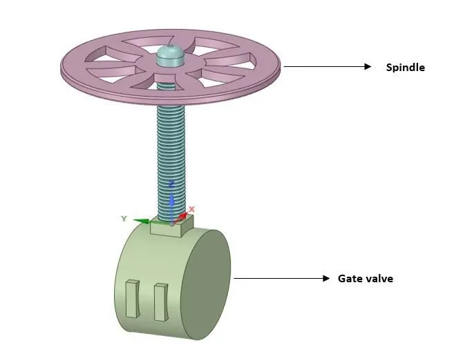
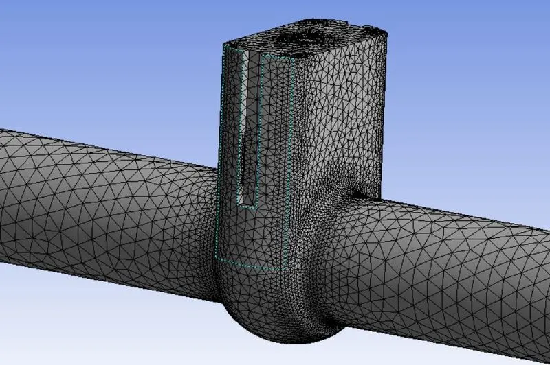
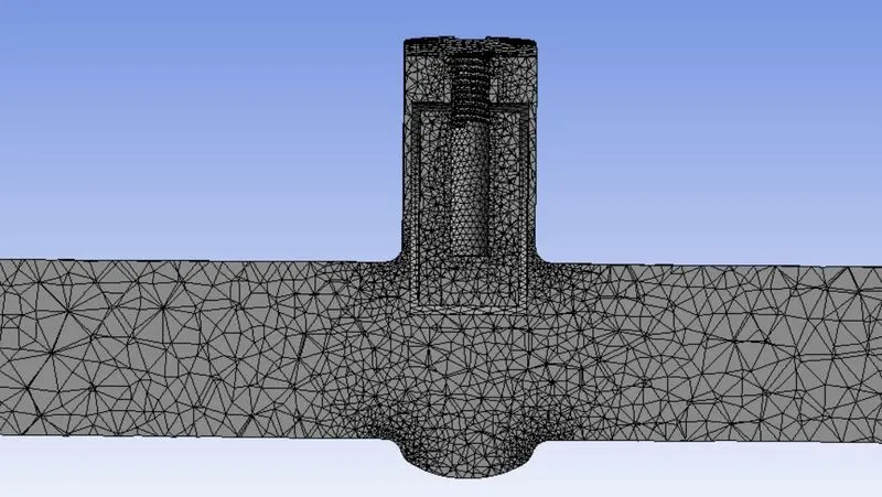
A simplified 3d geometry has been created consisting of various components of a gate valve system. Then fluid volume has been extracted using the volume extract feature in spaceclaim. The parameterization of the gate lift value is done by clicking in the 'P' option in spaceclaim.
MESH SETTINGS
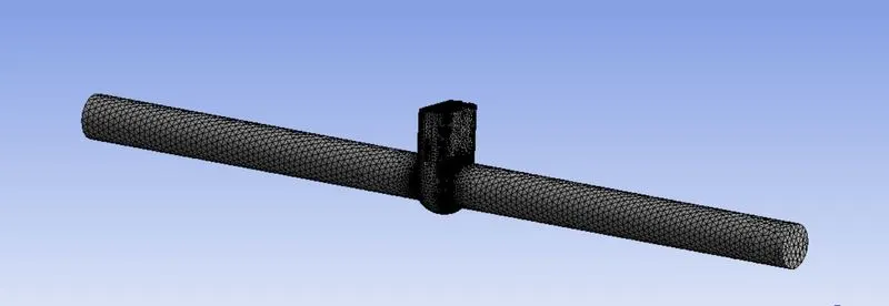
element size = 2mm
no. of elements = 151977
element quality - min =2.0613e-003 , max = 1
CFD CASE SETUP
General settings: -
A Steady state simulation has been carried out to predict the mass flow rate for different opening of the gate valve ranging from 10mm to 80mm.
Gravity: - 9.81 m/s in negative Z direction
Solver settings
Solver – Pressure based solver.
Materials specification
Material used: - Water
Density = 998.13 kg/m3
Viscosity = 0.001003 kg/(m-s)
Viscous model
K-epsilon model (Realizable)
Near wall treatment – scalable wall function
Boundary conditions
Inlet = pressure inlet
Gauge pressure = 10 pa
Outlet = pressure outlet
Gauge pressure = 0 pa
RESULTS AND DISCUSSIONS: -
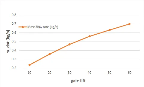
The simualtion has been carried out for different valve lift ranging from 10% to 80% and relevant plots and contours have been shown to understand the variation in mass flow rate at outlet.
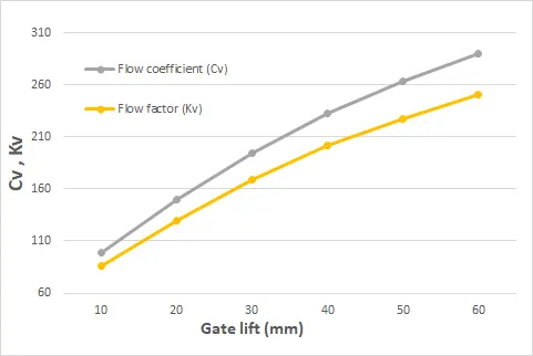
The valve flow coefficient Cv and flow factor Kv has also been calculated to measure the capacity of gate valve.
FLOW COEFFICIENT (Cv)
The valve flow coefficient, Cv is the number of U.S gallons per minute of water at 60 deg F that will flow through a control valve at a specified opening when a pressure differential of 1 psi is applied across the valve.
it is calculated as
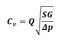
where;
Q = flow rate ( in US gallons per minute)
SG = Specific gravity of fluid referenced to water at 60 deg F
Δp = Pressure drop across the control valve
These simple equations helps us to understand the underlying principle of valve sizing. If we know the value of SG and pressure conditions of the fluid and we have the Cv of the valve at particular opening then we can predict the amount of flow that will pass through the valve.
FLOW RATE (Kv)
It is the metric equivalent of flow coefficient and is calculated using metric units.
mathematically it is represented as: -
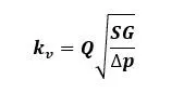
Kv = 0.865 * Cv
Q = flow rate (m3/kg)
SG = specific gravity of fluid
Δp = pressure drop (bar)
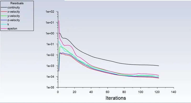
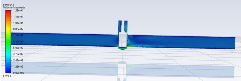
case 1: - lift = 10 mm
Residual plot
velocity contour
mass flow rate
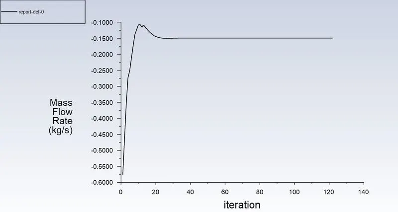
m_dot = 0.14945 kg/s
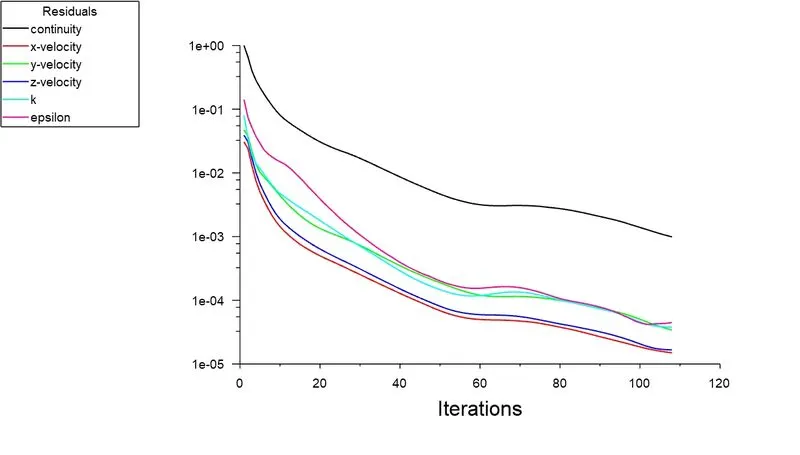
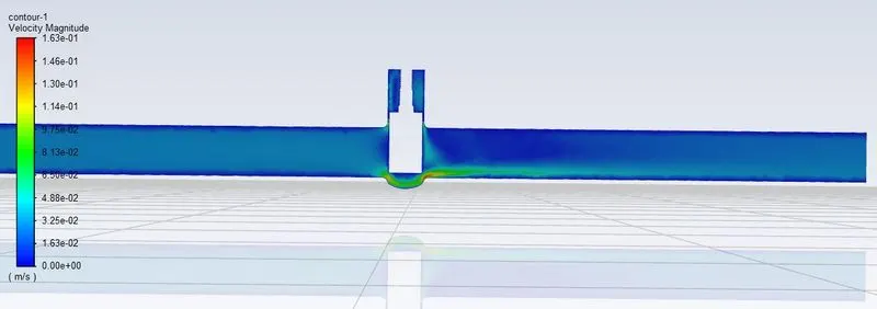
Case 2: - Lift = 20mm
Residual plot
velocity contour
mass flow rate
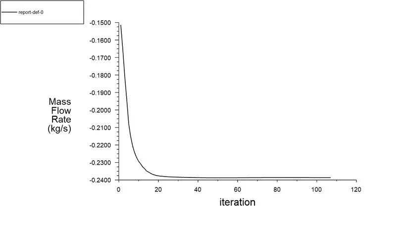
m_dot = 0.23866 kg/s
Case 3: - Lift = 30 mm
residual plot
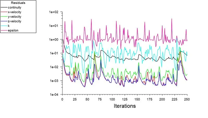
velocity contour
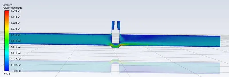
mass flow rate
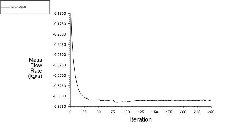
m_dot = 0.3598 kg/s
Case 4:- Lift = 40 mm
residual plot
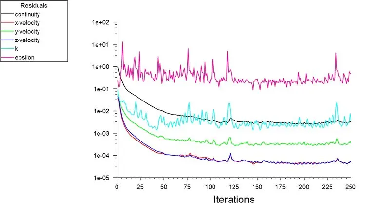
velocity contour
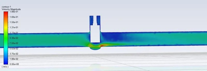
mass flow rate
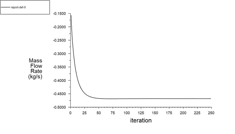
m_dot = 0.46824 kg/s
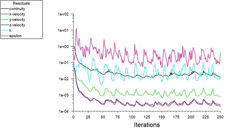
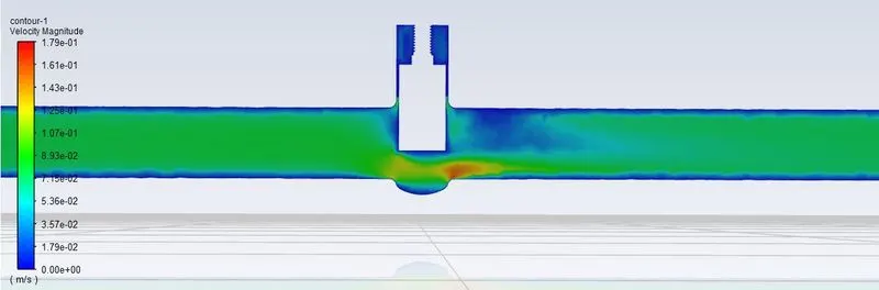
Case 5:- Lift = 50 mm
residual plot
velocity contour
mass flow rate
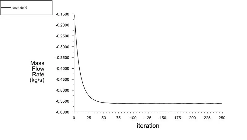
m_dot = 0.55999 kg/s
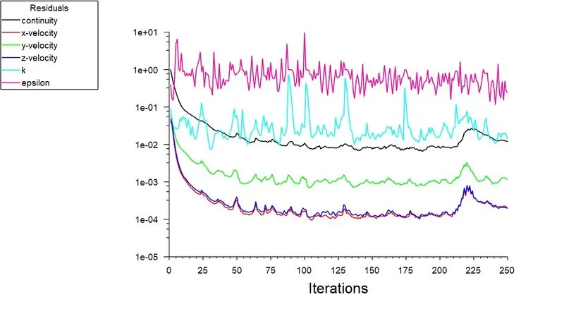
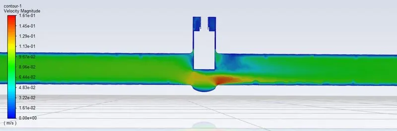
Case 6:- Lift = 60 mm
residual plot
velocity contour
mass flow rate
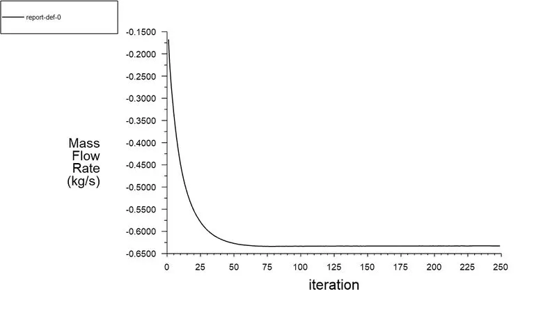
m_dot = 0.63283 kg/s
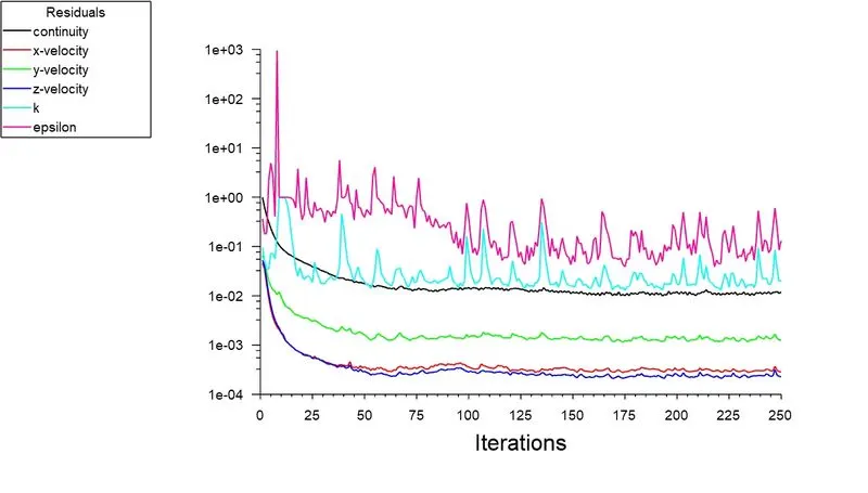
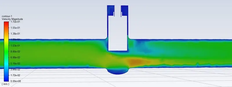
Case 7:- Lift = 70 mm
Residual plot
Velocity contour
mass flow rate
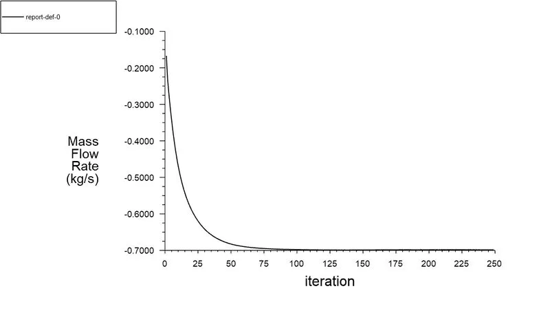
m_dot = 0.69828 kg/s
Case 8:- Lift = 80 mm
Residual plot
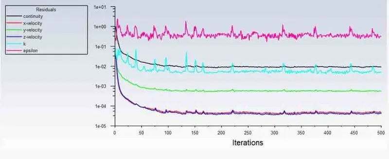
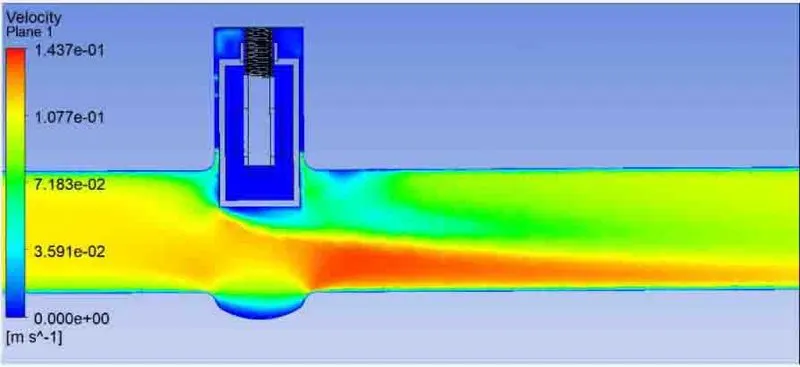
Velocity contour
mass flow rate
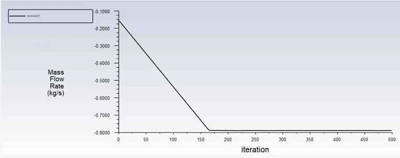
m_dot = 0.78510 kg/s
CALCULATIONS:
Q = 1kg/s = 3.6 m^3/hr
Δp = 1pa = 1*10^-5 bar
CASE 1: -
Q = 0.14945 kg/s = 3.6*0.14945 = 0.53802 m^3/hr
Δp = 10*10^-5 bar
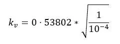
kv = 53.802
CASE 2: -
Q = 0.23865 kg/s = 3.6*0.23865 = 0.85914 m^3/hr
Δp = 10*10^-5 bar
kv = 85.914
CASE 3: -
Q = 0.35979 kg/s = 3.6*0.35979 = 1.29524 m^3/hr
Δp = 10*10^-5 bar
kv = 129.524
CASE 4: -
Q = 0.46823 kg/s = 3.6*0.46823 = 1.6856 m^3/hr
Δp = 10*10^-5 bar
kv = 168.56
CASE 5: -
Q = 0.5599 kg/s = 3.6*0.5599 = 2.0156 m^3/hr
Δp = 10*10^-5 bar
kv = 201.56
CASE 6: -
Q = 0.63282 kg/s = 3.6*0.63282 = 2.27815 m^3/hr
Δp = 10*10^-5 bar
kv = 227.815
CASE 7: -
Q = 0.69827 kg/s = 3.6*0.69827 = 2.5137 m^3/hr
Δp = 10*10^-5 bar
kv = 251.37
CASE 8: -
Q = 0.78510 kg/s = 3.6*0.78510 = 2.82636 m^3/hr
Δp = 10*10^-5 bar
kv = 282.636
similarly Cv for each case:-
Cv = Kv/0.865
1. Cv = 62.198
2. Cv = 99.322
3. Cv = 149.738
4. Cv = 194.867
5. Cv = 233.017
6. Cv = 263.369
7. Cv = 290.601
8. Cv = 326.746
OBSERVATION TABLE: -
|
Cases |
Gate valve lift (mm) |
Mass flow rate (kg/s) |
Flow coefficient (Cv) |
Flow factor (Kv) |
|
1 |
10 |
0.14945 |
62.198 |
53.802 |
|
2 |
20 |
0.23865 |
99.322 |
85.914 |
|
3 |
30 |
0.35979 |
149.738 |
129.524 |
|
4 |
40 |
0.46823 |
194.867 |
168.56 |
|
5 |
50 |
0.5599 |
233.017 |
201.56 |
|
6 |
60 |
0.63282 |
263.369 |
227.815 |
|
7 |
70 |
0.69827 |
290.601 |
251.37 |
|
8 |
80 |
0.78510 |
282.636 |
326.746 |
CONCLUSIONS
1. The mass flow rate is found to increase from 0.14945 to 0.78510 kg/s as the gate lift opens from 10 mm to 80mm.
2. With the increase in gate lift Cv and Kv value also increases. These values helps to decide the valve sizing.
3. The parametric analysis reduces the computational time and cost and we can easily calculate the effect of different design points on the results.