Week 9 - Parametric study on Gate valve.
OBJECTIVE OF THE SIMULATION:
1. To perform a parametric study on the gate valve by opening it from 10-80%.
2. To find mass flow rate on each design point at the outlet, and calculating the flow coefficient & understanding these parameters association with valve lift.
THEORY:
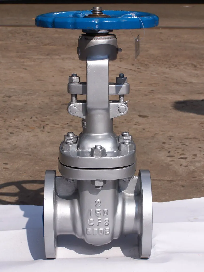
A gate valve, also known as the sluice valve is a flow regulation device. It works by mechanically lifting a valve or a barrier gate. The main reason why gate valves are of great importance is that they occupy very less space along the pipe axis. This makes them a very useful and preferable component when we talk of systems having space constraints. When the gate valve is fully open, there is no obstruction of the flow path.
The size of the orifice opening varies non-linearly as the gate is moved, this means that the changes in flow rate are not even too, even fully open gates vibrate due to fluid flow.
High-pressure pipelines have small tweaks and factors have to be considered in the gate valve design. In high-pressure systems, the fluid pushes against the gate, this, in turn, increases friction between the gate and the guide railings, easy operation of the valve hence becomes difficult. In such systems, we need to employ by-pass controllers to reduce the operating pressure. The issue of sealing comes where leaking becomes very crucial to the integrity of the design.
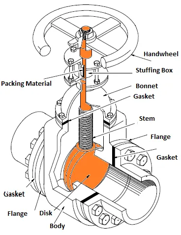
The basic design layout of the gate valve is, the handwheel or motor is the actuator, which is connected to a threaded stem. The common link between the actuator and the thread is a nut that is rotated around the stem to move it. When vertical motion is prohibited non-rising stems are used, where they are fixed, rotate with the actuator.
Gate valves are made of cast iron, cast carbon steel, ductile iron, gunmetal, etc.
Apart from the gate valve, the bonnet is a very important component it ensures that the gate valve is sealed, depending on the operating pressure the method of attachment of the bonnet changes, they can be bolted or pressure sealed.
A diagram showing the internal construction of a valve:
A parametric study is a process through which we can simulate the complete problem statement in different scenarios, rather than just repeating the whole process of simulation over and over again. We just need to pick a quantity that we need to parametrize.
FLOW COEFFICIENT & FLOW FACTOR:
The flow coefficient is the quantified measure or a relative measure of its efficiency at allowing fluid flow. It describes the relationship between the pressure drop across an orifice valve and the corresponding flow rate.
Mathematically it is described as:

Here Q is the mass flow rate, SG is specific gravity, Delta P is pressure drop across orifice. Practically it is basically the volume of water in gallons that can flow across the pipe with 1 psi pressure. This gives us a quantitative comparing factor between valves.
For other fluids, the equation can be further modeled from the discharge co-efficient formula.
The flow factor is the metric equivalent of the flow coefficient. The units of pressure are in bar, the units of Kv the flow factor is m^3/hr.
The conversion formula is Kv=0.865*Cv.
SETUP & MESHING:
For our simulation, we are going to create the upward movement of the gate as a parameter. We are going to simulate the flow variables from 10mm-80mm of gate lift, in coherence with the conditions above.
1. To import the gate valve cad model in the space claim:
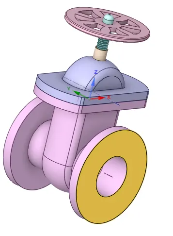
Ensure that all the solid parts are present like the handle, spindle, bonnet, bottom case assembly, gear disc, etc.
2. The first step we do is to pull the model on either side so that the downstream flow also can be visualized in the pipe system.
3. Then we click prepare and extract the fluid volume, it's important we select the inner edges so that errors in meshing can be avoided.
4. Post getting the fluid volume, delete parts like handle, bonnet, bottom spindle. Suppress the gate for physics.
5. The select the option of the move, move the gate disc till 10mm, create a parameter, with ruler dimensions as 10mm.
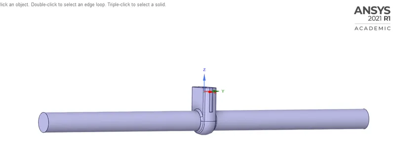
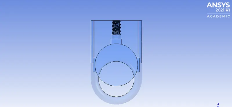
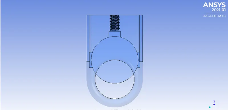
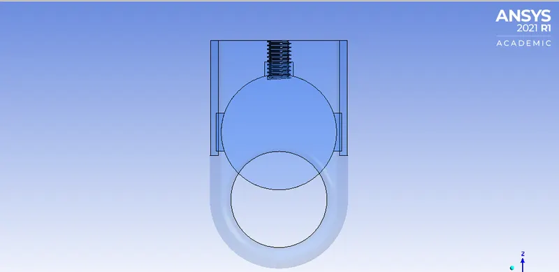
The prepared fluid volume is like this:
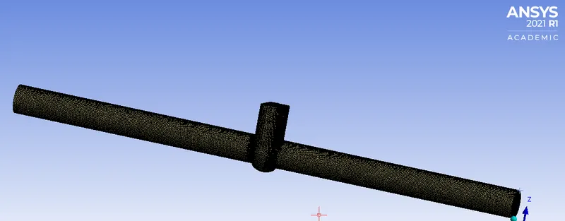
We then proceed to mesh:
1. We create a finer mesh of about 6mm element size, setting smoothening to high.
Elements- 414024, Nodes- 84181
2. Appropriate named selections like inlet & outlet to be given:
SETUP:
1. Pressure-based steady-state solver, with gravity, enabled, in our case in the negative z-direction.
2. The k-epsilon realizable model, with scalable wall functions.
3. Set the material to water, ensure the volume in cell zone conditions also has water.
4. Set the boundary conditions as following, the inlet as a pressure inlet with 10 Pa pressure, the outlet as pressure outlet 0 gauge pressure.
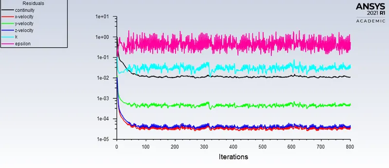
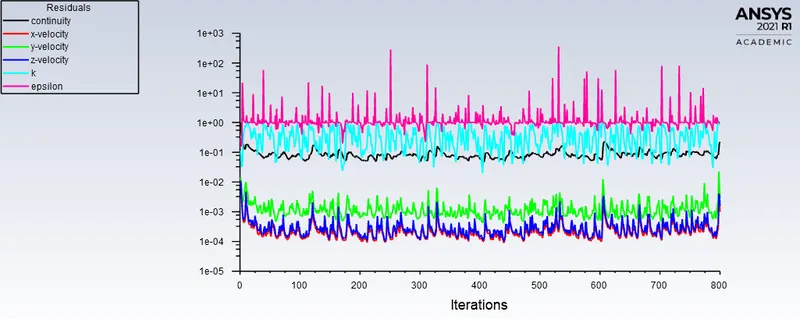
5. Uncheck the residuals, and standard initialize, from the inlet.
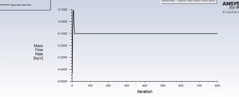
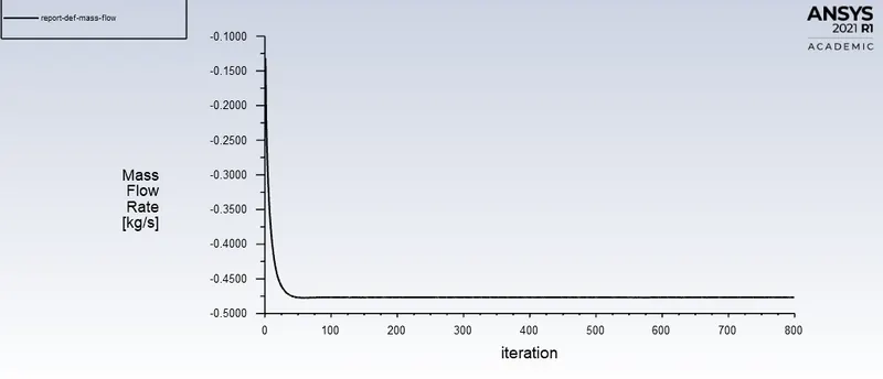
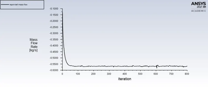
6. Make plots for the mass flow rate, ensure we turn the parameter option on, also create contours for velocity & pressure.
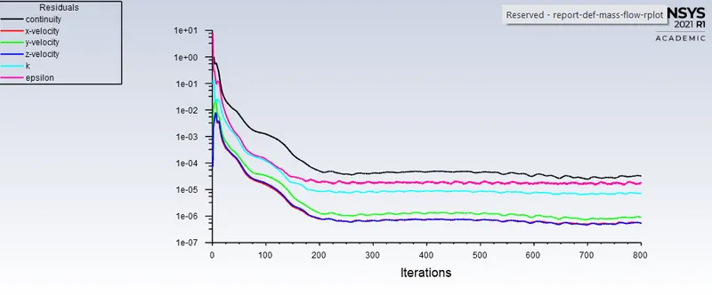
7. Run the simulation for at least 800 iterations.
RESULTS & CALCULATIONS:
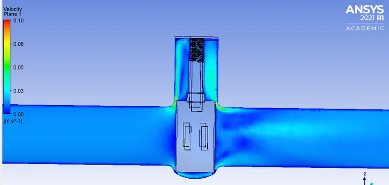
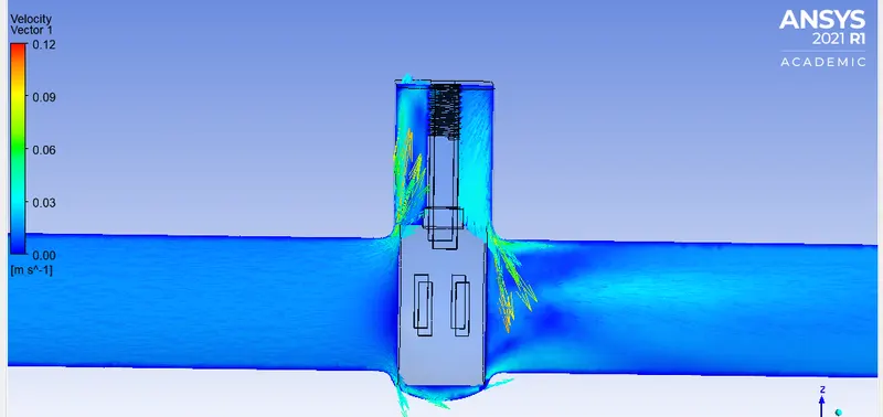
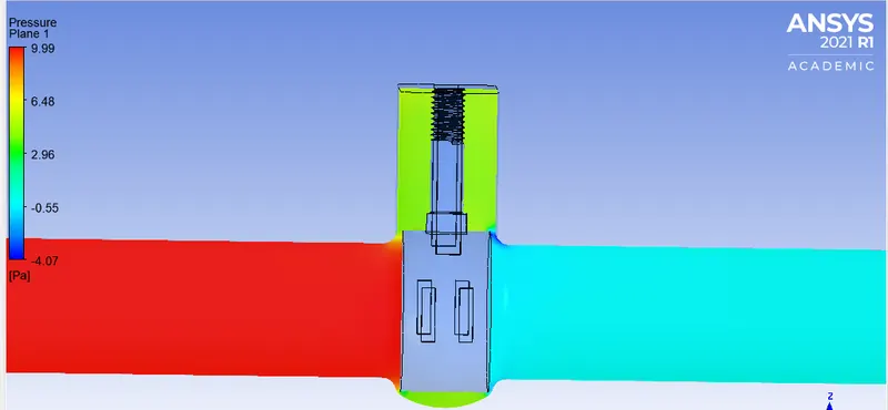
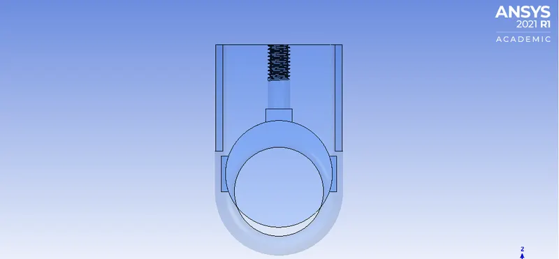
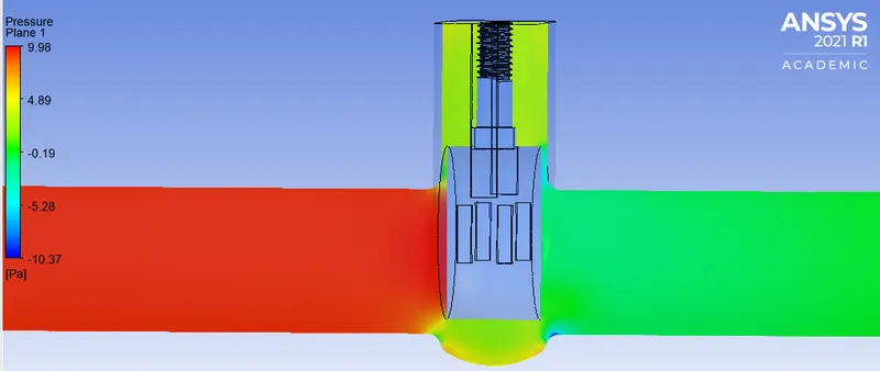
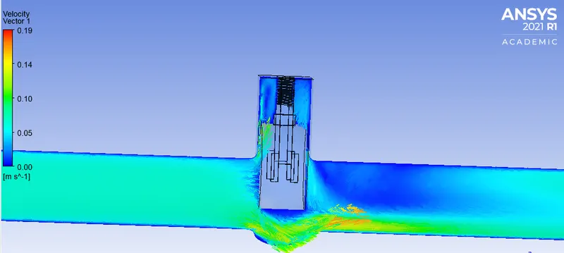
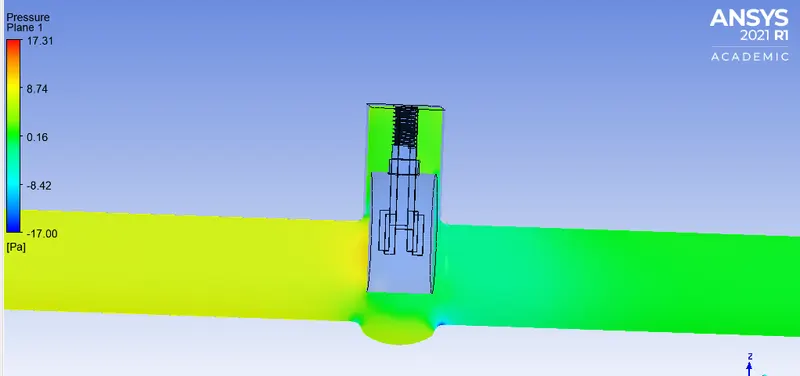
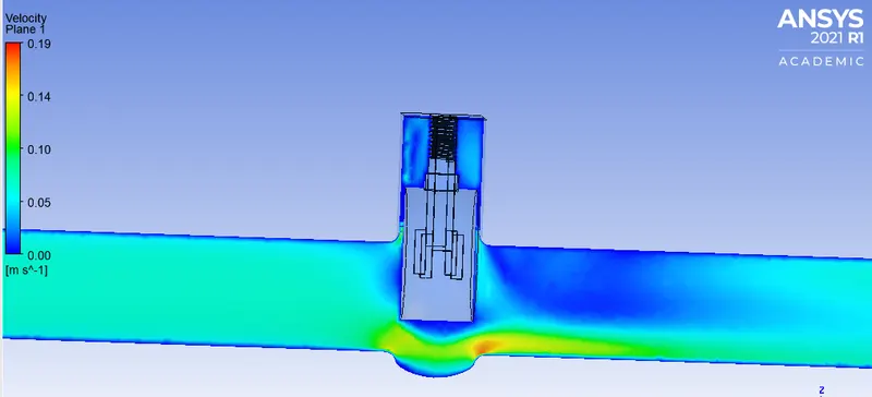
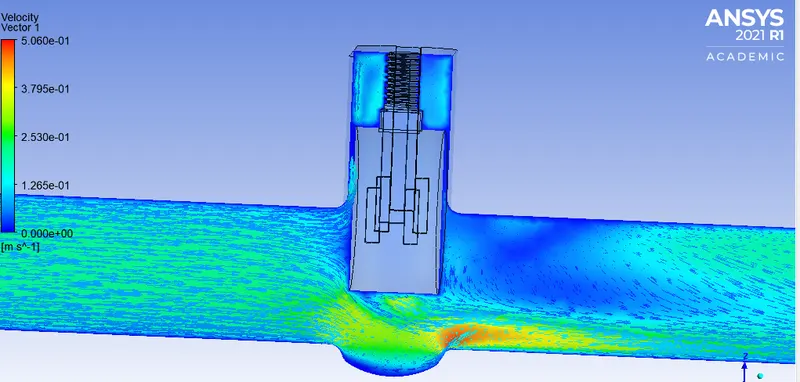
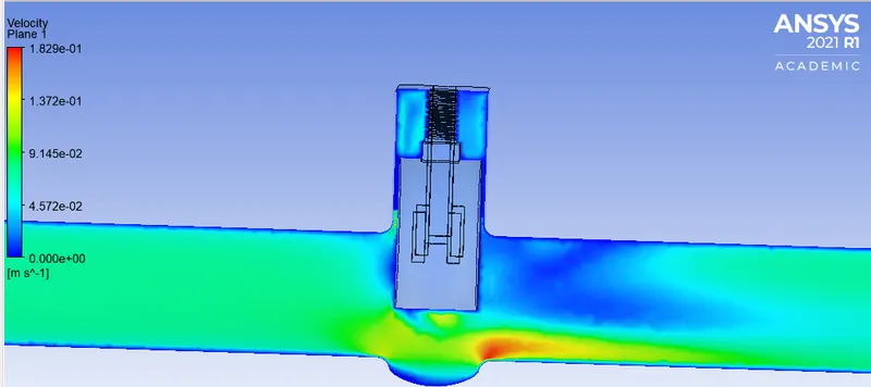
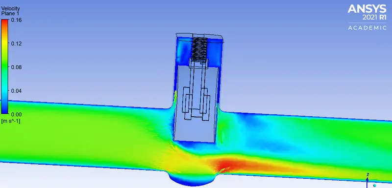
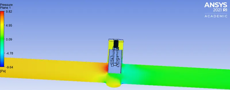
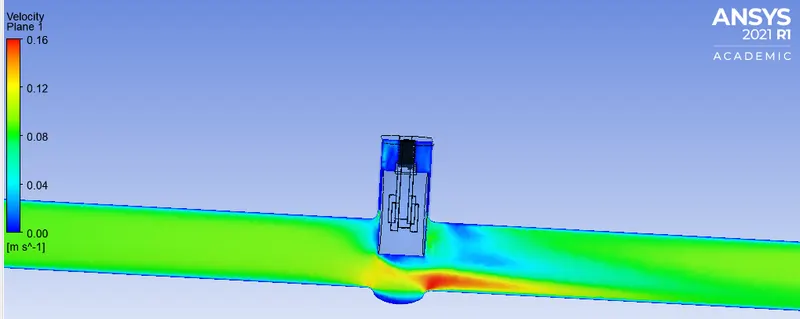
The pictures show velocity, pressure, velocity vector plots.
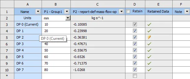
The parametric table,
For 10:
For 20:
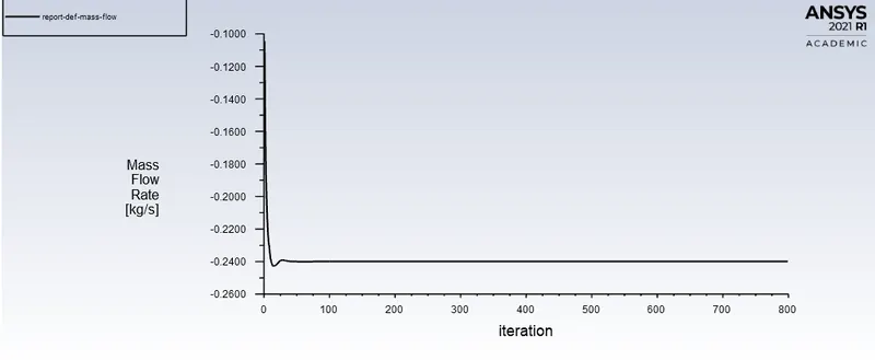
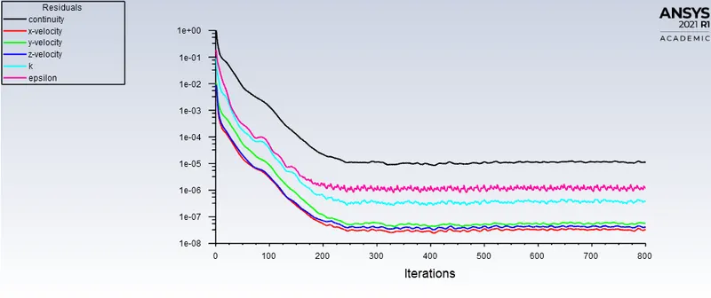
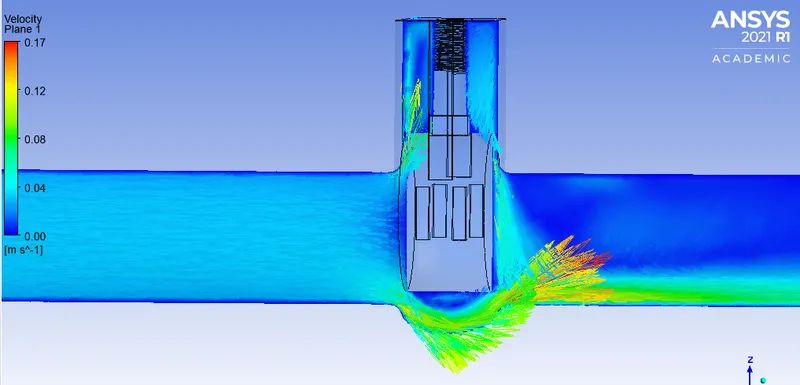
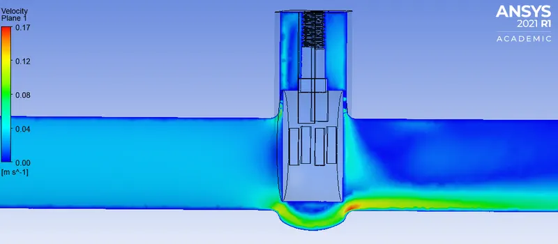
For 40:
For 50:
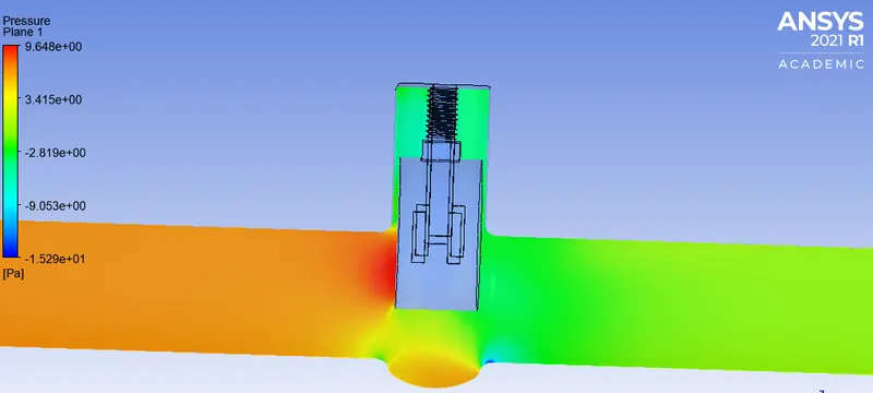
For 60:
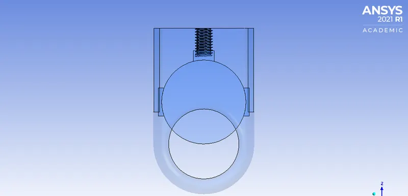
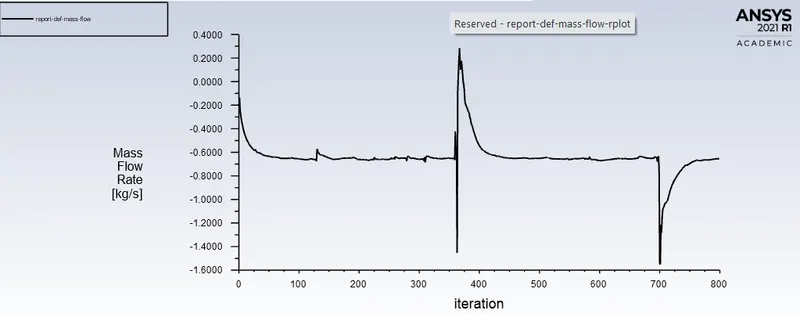
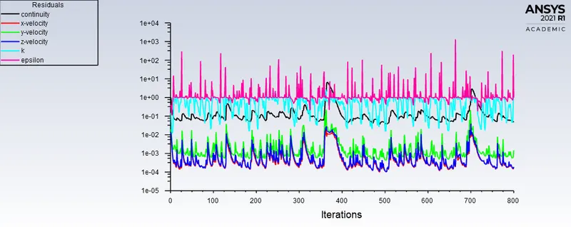
For 70:
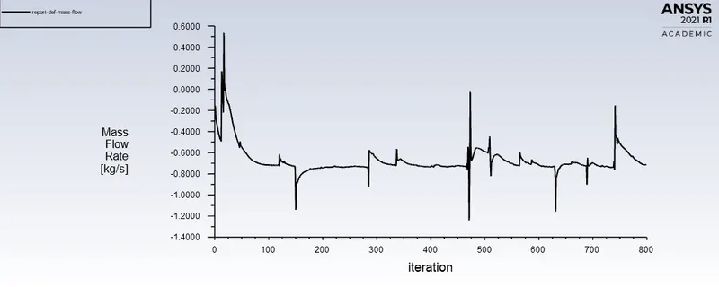
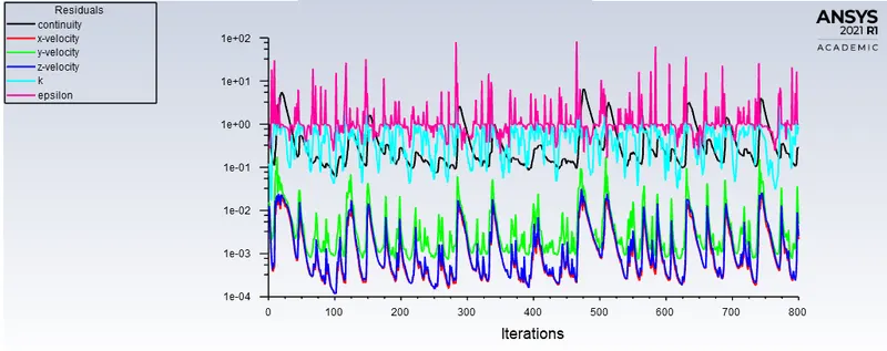
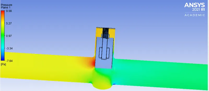
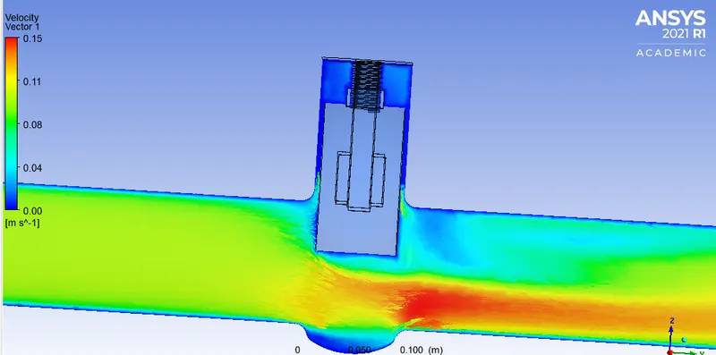
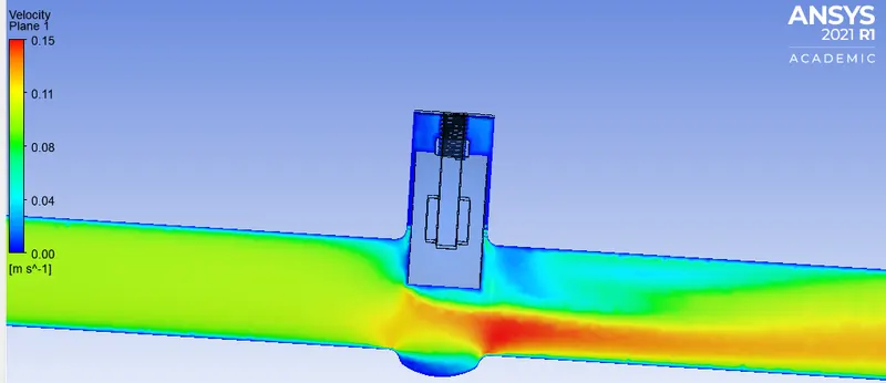
For 80:
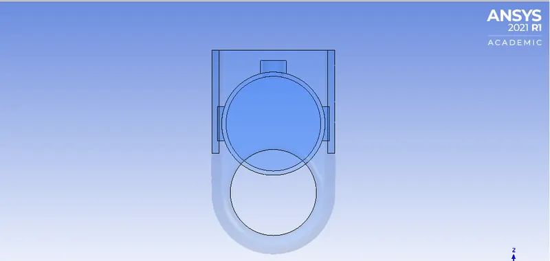
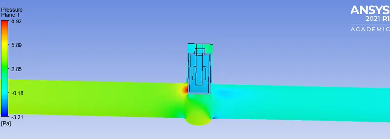
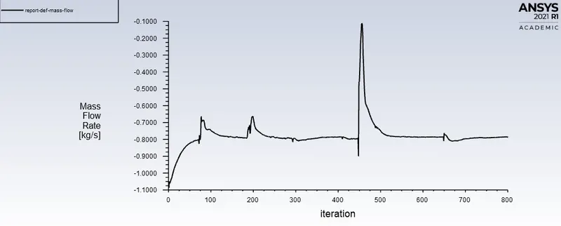
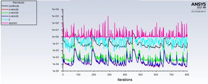
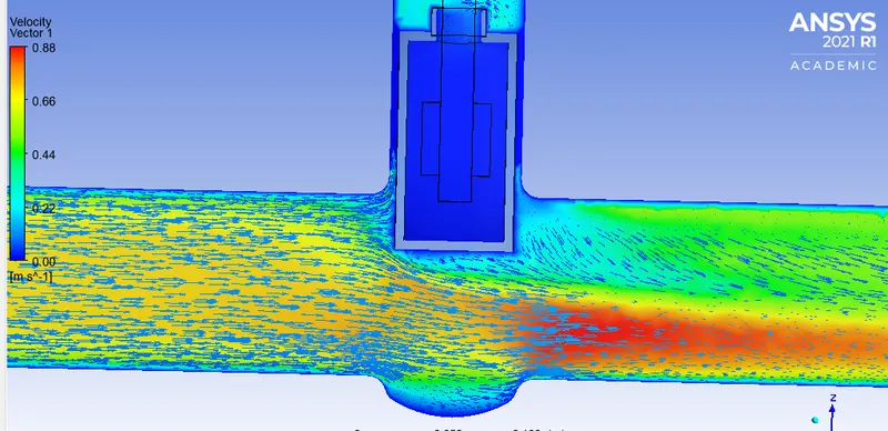
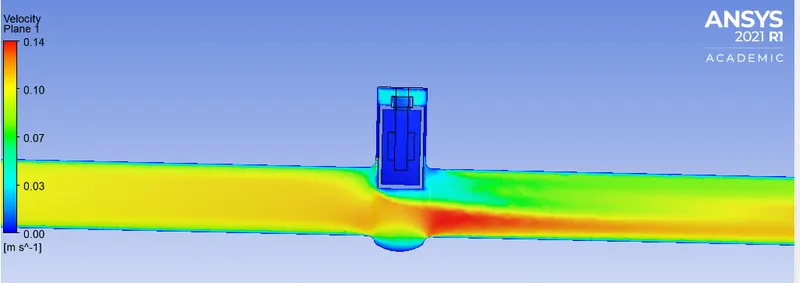
For the calculation, we look at these basic pointers, from the formula we need Delta P, SG
The SG can be calculated as 1000/998.2=1, The Delta P is the difference of pressure of the Inlet and Outlet which is 10 Pa ( Guage pressure outlet is zero), to convert this in psi we multiply it by 0.000145, which is a small value, hence we take Delta P as 10 Pa.
For 10mm:
Cv=Q*sqrt(1/Delta P)
Kv=0.865*Cv
Cv=0.10085*sqrt(1/10)
Cv=0.03189
Kv=0.865*0.03189
Kv=0.0275
For 20mm:
Cv=Q*sqrt(1/Delta P)
Kv=0.865*Cv
Cv=0.23998*sqrt(1/10)
Cv=0.07588
Kv=0.865*0.07588
Kv=0.06563
For 30mm:
Cv=Q*sqrt(1/Delta P)
Kv=0.865*Cv
Cv=*sqrt(1/10)
Cv=0.15074
Kv=0.865*0.15074
Kv=0.0275
For 40mm:
Cv=Q*sqrt(1/Delta P)
Kv=0.865*Cv
Cv=0.4761*sqrt(1/10)
Cv=0.15074
Kv=0.865*0.15074
Kv=0.1303
For 50mm:
Cv=Q*sqrt(1/Delta P)
Kv=0.865*Cv
Cv=0.55675*sqrt(1/10)
Cv=0.17605
Kv=0.865*0.17605
Kv=0.1303
For 60mm:
Cv=Q*sqrt(1/Delta P)
Kv=0.865*Cv
Cv=0.6525*sqrt(1/10)
Cv=0.2063
Kv=0.865*0.2063
Kv=0.17851
For 70mm:
Cv=Q*sqrt(1/Delta P)
Kv=0.865*Cv
Cv=0.71375*sqrt(1/10)
Cv=0.225707
Kv=0.865*0.225707
Kv=0.19523
For 80mm:
Cv=Q*sqrt(1/Delta P)
Kv=0.865*Cv
Cv=0.783027*sqrt(1/10)
Cv=0.24761
Kv=0.865*0.03189
Kv=0.21418
| GATE LIFT IN MM. | MASS FLOW RATE (KG/S). | FLOW COEFFICIENT | FLOW FACTOR |
| 10 | 0.10085 | 0.03189 | 0.0275 |
| 20 | 0.23998 | 0.07588 | 0.06563 |
| 30 | 0.36381 | 0.11504 | 0.09951 |
| 40 | 0.47671 | 0.15074 | 0.1303 |
| 50 | 0.55675 | 0.17605 | 0.15229 |
| 60 | 0.6526 | 0.2063 | 0.17851 |
| 70 | 0.71375 | 0.225707 | 0.19523 |
| 80 | 0.783027 | 0.24761 | 0.21418 |
CONCLUSIONS:
1. The velocity in the first case is very low, as the gate opens the velocity of the flow gradually increases.
2. The pressure also decreases along with the flow.
3. The mass flow rate, flow coefficient, flow factor all become maximum when the valve is fully open.