Week 9 - Parametric study on Gate valve.
Parametric Study On The Gate Valve Simulation
A parametric study on a gate valve simulation involving the setting of the opening refers to the investigation of the valve's performance and behavior by varying the valve opening. The study aims to analyze how different opening positions affect the flow characteristics, pressure drop, and other relevant parameters.
By conducting this parametric study, we can gain insights into the relationship between the gate valve opening and its impact on flow characteristics, pressure drop, and other relevant parameters..These insights can guide the optimization of valve design, system efficiency, and operational parameters for improved performance and reliability.
SIMULATION SETUP
GEOMETRY PREPERATION
The given model is openeed in ANSYS SpaceClaim
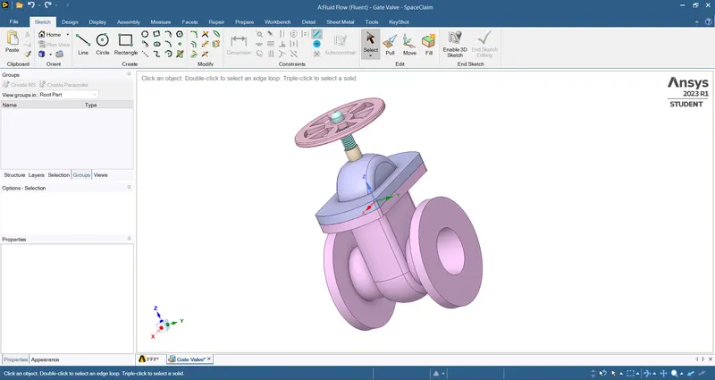
PULL option is used to extend the inlet and outlet by 800 mm
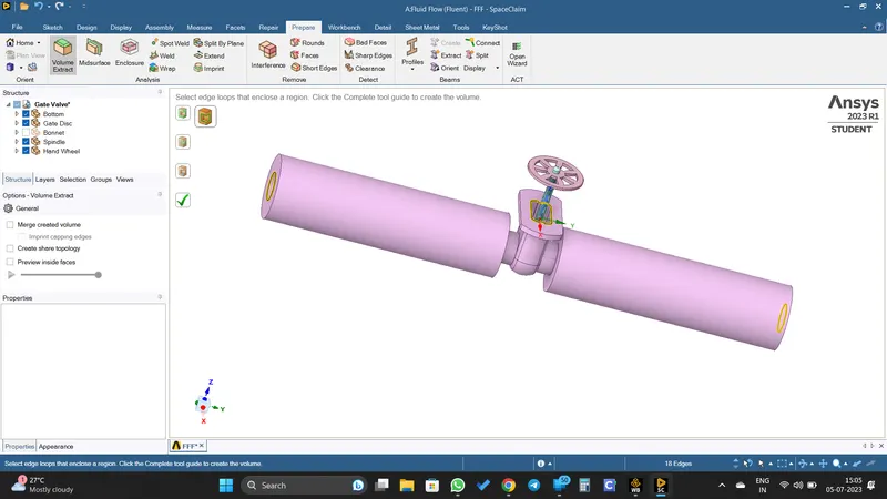
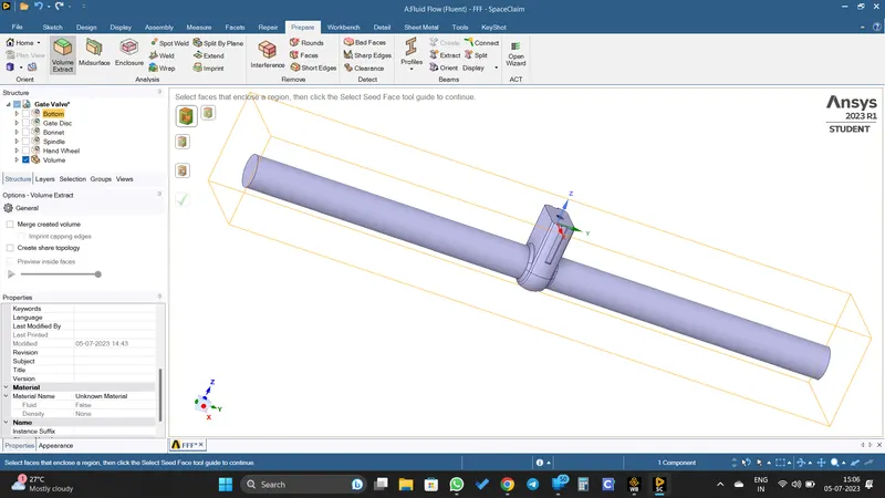
And the fluid volume is extracted.
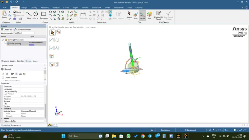
Then the valve gate opening is parameterized.
MESHING
Then the model is opened in meshing window.
Given the name selection.
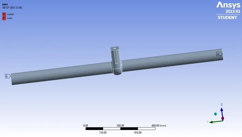
Mesh is created
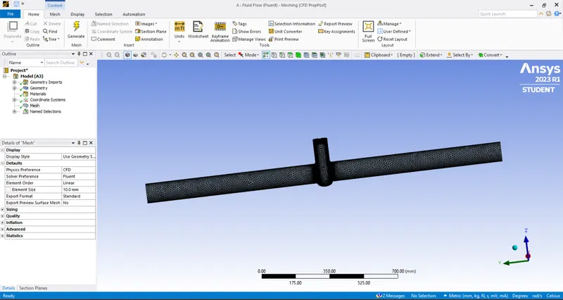
Mesh Element size is 10 mm
SIMULATION SETUP
The meshed model is opened in ANSYS Fluent.
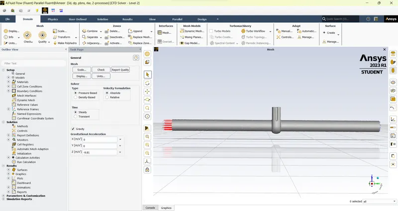
Simulation Parameters
- Solver Type: Pressure-based, steady state solver
- Gravity is enabled (9.81 `m`/`s^2` in -Z direction)
- Viscous Model: k-epsilon - Realizable - Scalable Wall Function
- Material Selected: Water (liquid)
- Boundary Condition;
Inlet: Pressure Inlet (10 Pa)
Outlet: Pressure Outlet (0 Pa)
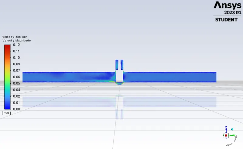
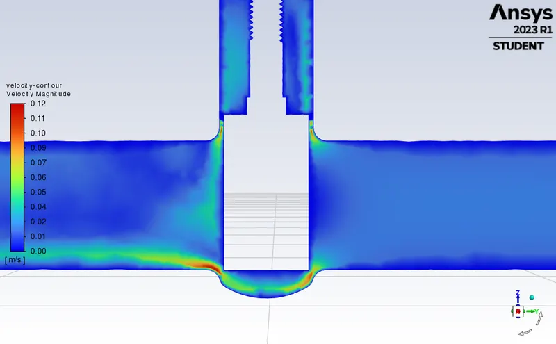
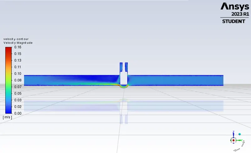
- Created the velocity contour in ZY plane
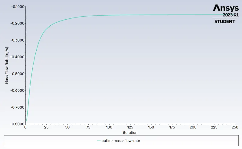
- Created the report for the mass flow rate at the outlet and checked 'create output parameter' for parameteric study.
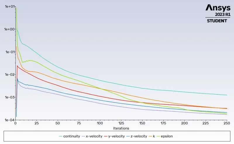
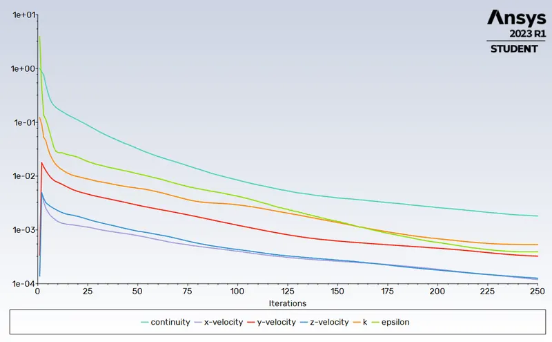
- Number of iteration: 250
PARAMETRIC STUDY SETUP
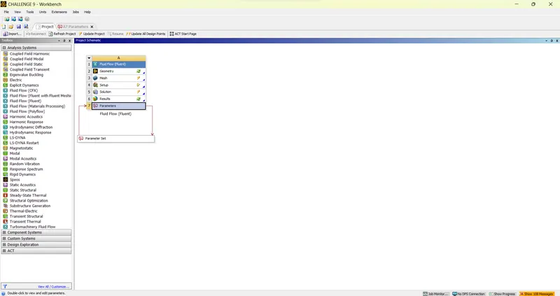
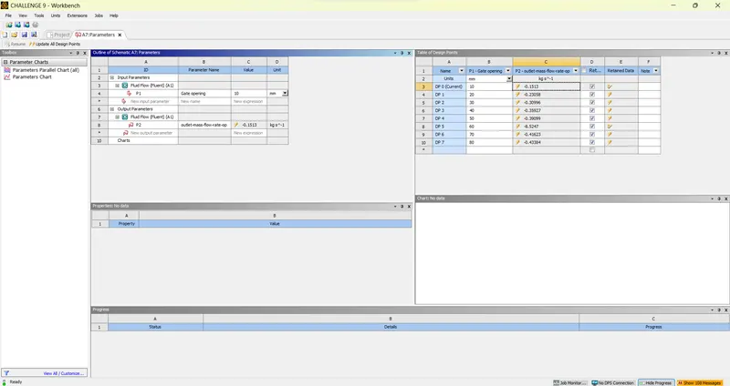
8 design points are created corresponding to gate opening of 10 mm, 20 mm, 30 mm upto 80 mm.
RESULTS
Mass Flow Rates At The Outlet For Each Design Point
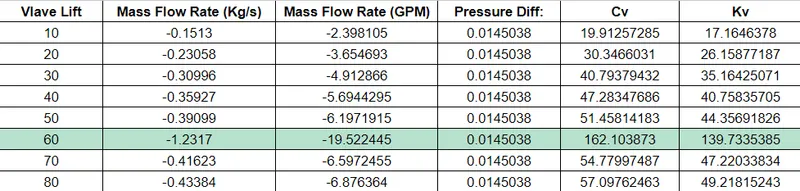
The table below shows the result obtained form the parametric study.
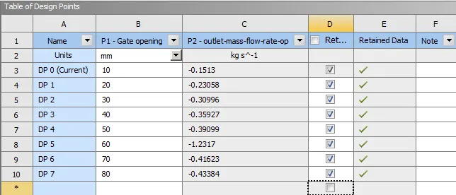
DP 0 - 10 mm lift
Residuals Plot
Velocity Contour
Outlet Mass Flow Rate
DP 01 - 20 mm lift
Residuals Plot
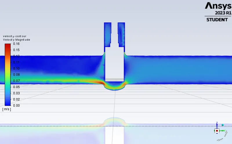
Velocity Contour
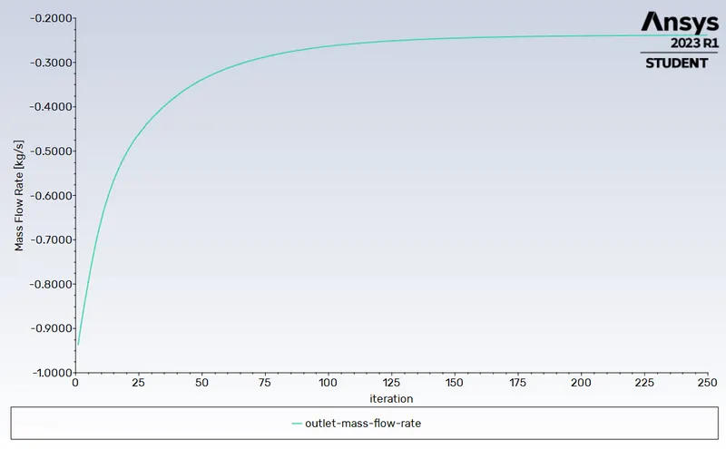
Outlet Mass Flow Rate
DP 02 - 30 mm lift
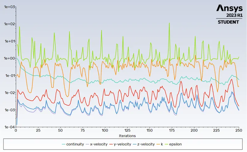
Residuals Plot
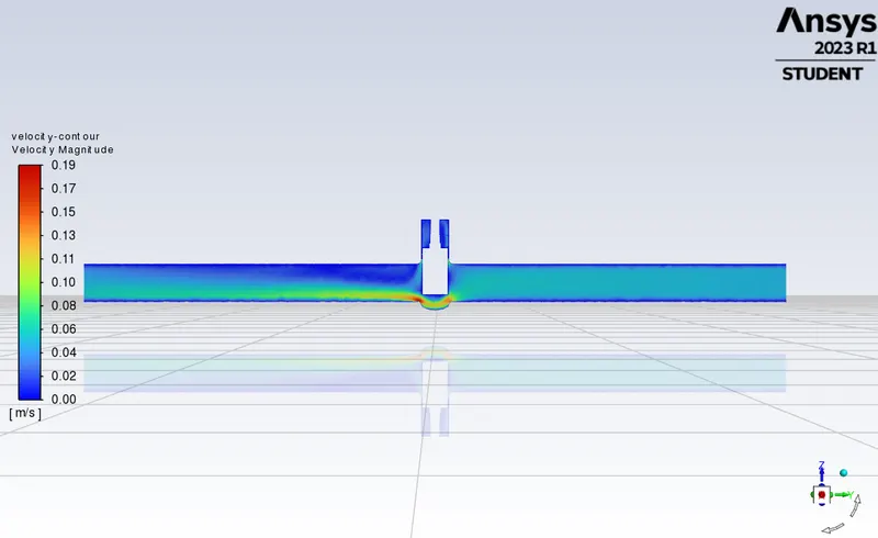
Velocity Contour
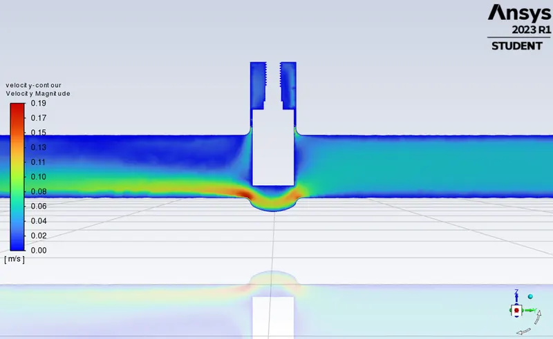
Outlet Mass Flow Rate
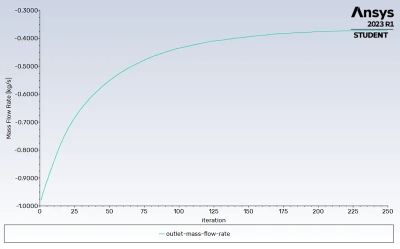
DP 03 - 40 mm lift
Residuals Plot
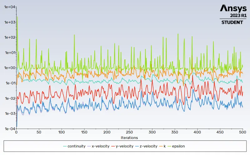
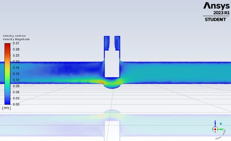
Velocity Contour
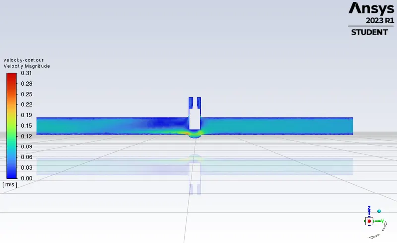
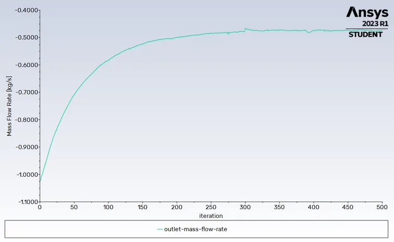
Outlet Mass Flow Rate
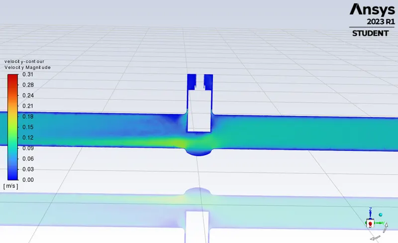
DP 04 - 50 mm lift
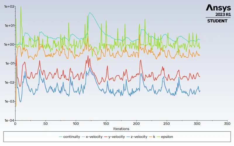
Residuals Plot
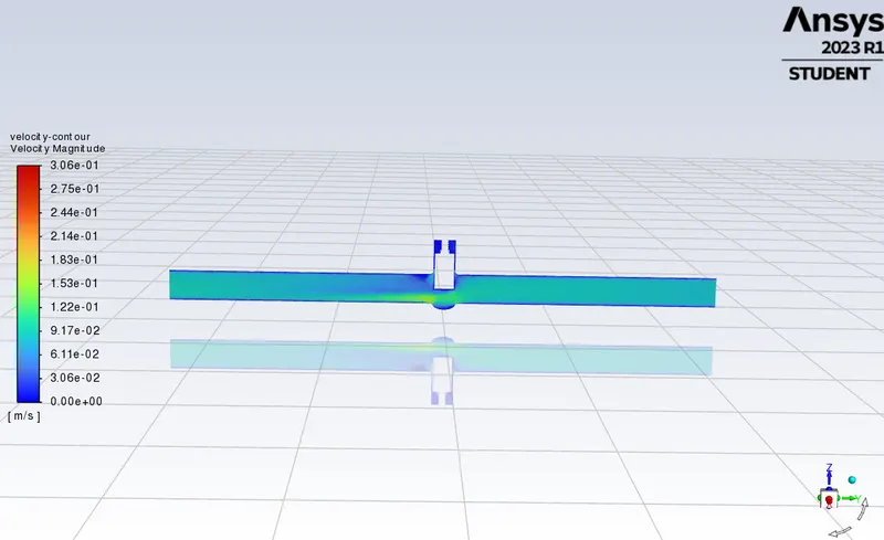
Velocity Contour
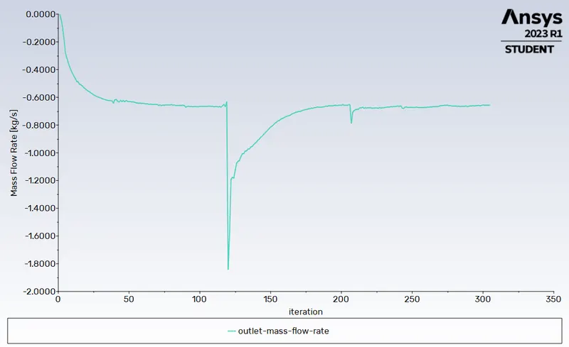
Outlet Mass Flow Rate
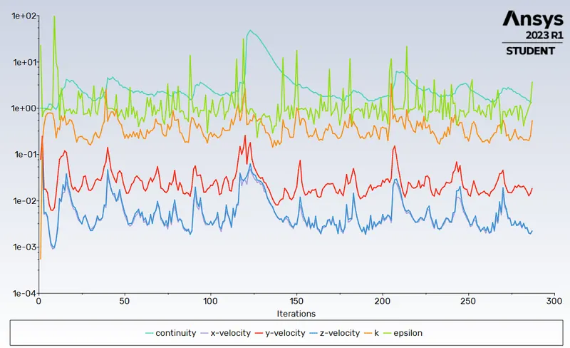
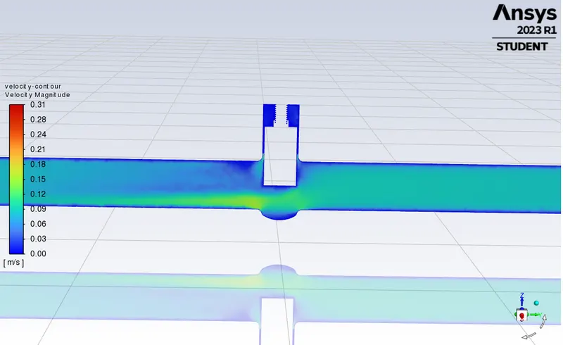
DP 05 - 60 mm lift
Residuals Plot
Velocity Contour
Outlet Mass Flow Rate
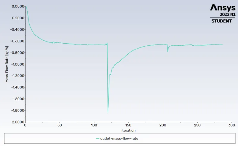
DP 06 - 70 mm lift
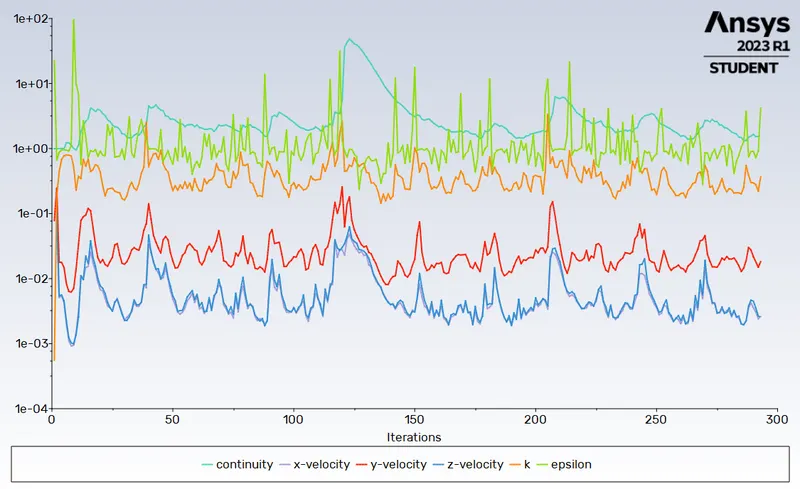
Residuals Plot
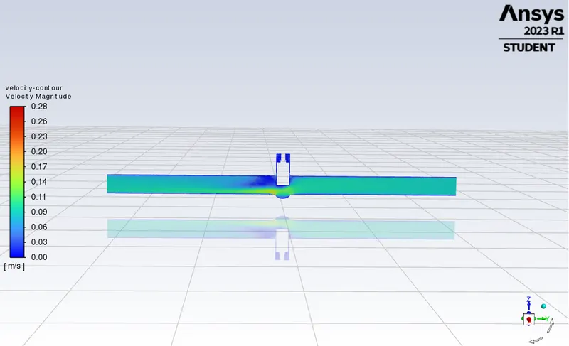
Velocity Contour
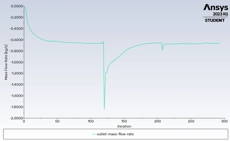
Outlet Mass Flow Rate
DP 07 - 80 mm lift
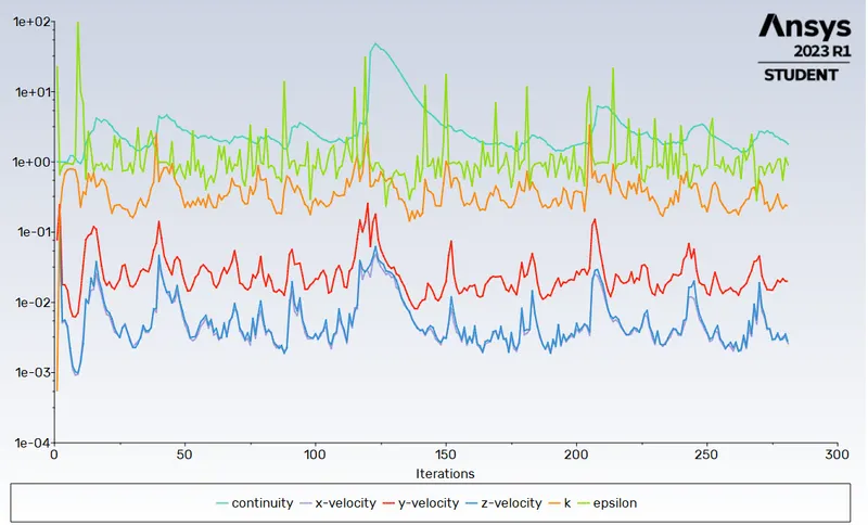
Residuals Plot
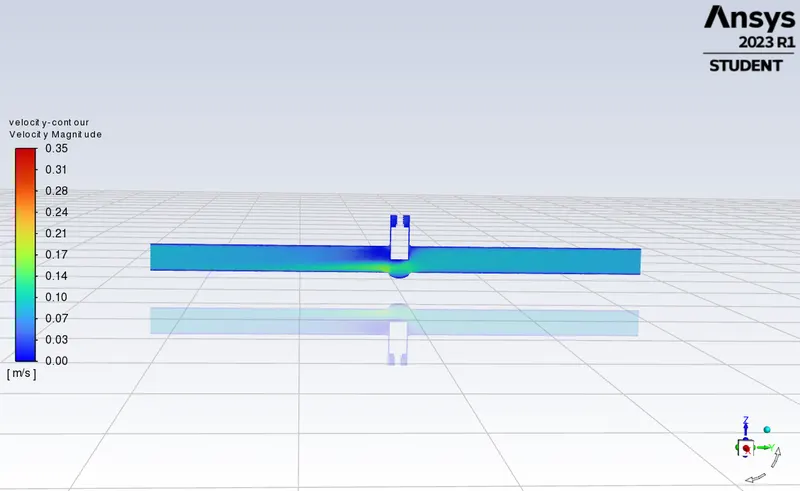
Velocity Contour
Outlet Mass Flow Rate
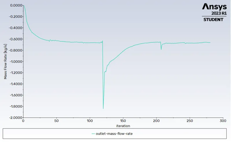
From this result, we can observe a slight variation between the results obtained from the parametric study and individual runs (especially for DP 5 - 60 mm lift). This variation may because of the following reasons:
- Round-off Errors: Numerical simulations involve calculations and iterations that can introduce small round-off errors. These errors can accumulate over time and potentially lead to slight variations in the results, even with the same input values.
- Solver Convergence: The convergence behavior of the solver can vary from run to run. Even though the same settings are used, the solver's convergence may not be identical due to the iterative nature of the solution process. This can result in minor differences in the final results.
- Mesh Independence: Although the mesh and settings were the same, it's possible that the simulations have not reached mesh independence. If the mesh is not fine enough or does not adequately capture the flow phenomena, the results may still vary, even if the input values are the same.
- Numerical Stability and Convergence: Parametric studies may introduce additional complexity, such as changes in flow patterns, turbulence behavior, or fluid-structure interactions. These complexities can impact the numerical stability and convergence of the simulations.
We can conduct additional runs to assess the repeatability of the results, and thereby validate them. However, due to time limitations and insufficient computational resources, we are unable to pursue that option at this time.
Flow Coefficient And Flow Factor
Flow Coefficient (Cv)
The flow coefficient (Cv) is a dimensionless value that represents the flow capacity of a valve for a given pressure drop. It is defined as the flow rate of water (in gallons per minute, GPM) that passes through the valve with a pressure drop of 1 psi (pound per square inch). The higher the Cv value, the greater the flow capacity of the valve. Cv is commonly used in North America.
`Cv = Q sqrt((SG)/(triangleP)`
`Q =>` Flow Rate (gal/min)``
`SG =>` Specific Gravity of Fluid (for water, `SG = 1`)
`triangleP =>` Pressure Drop Across the Valve (psi)
`=>` inlet pressure- outlet pressure = 10 - 0 = 10 Pa
Flow Factor (Kv)
The flow factor (Kv) is similar to Cv but is expressed in metric units. It represents the flow rate of water (in cubic meters per hour, m^3/h) that passes through the valve with a pressure drop of 1 bar. Kv is commonly used in Europe and other regions where the metric system is prevalent.
`Kv = 0.862 Cv`
The table below shows the values of `Cv` and `Kv`:
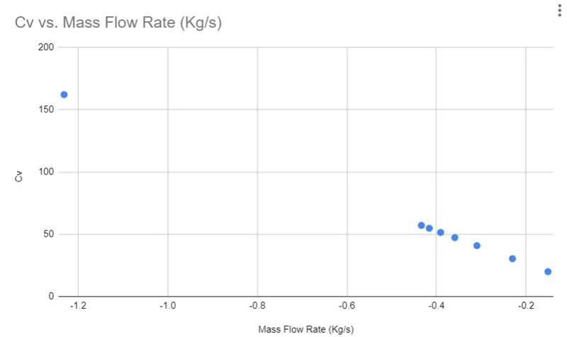
Graph of Cv vs Outlet Mass Flow Rate
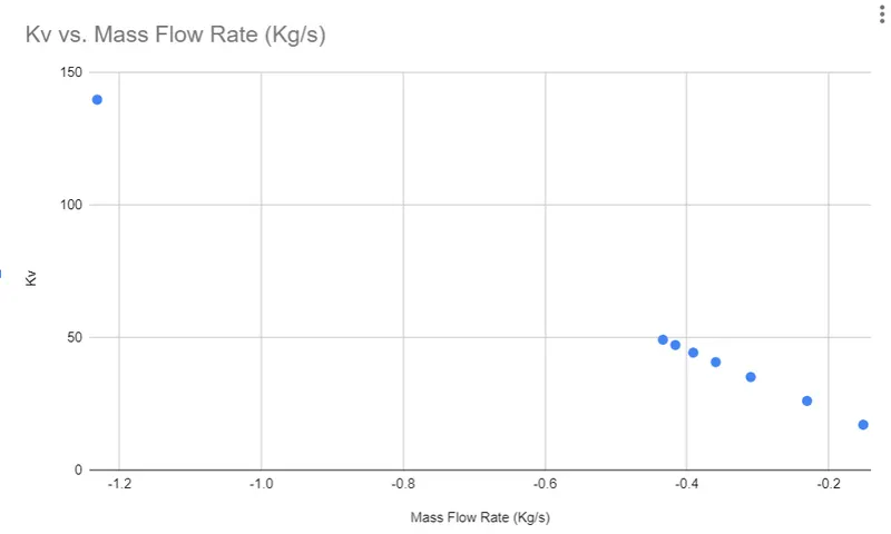
Graph of Kv vs Outlet Mass Flow Rate
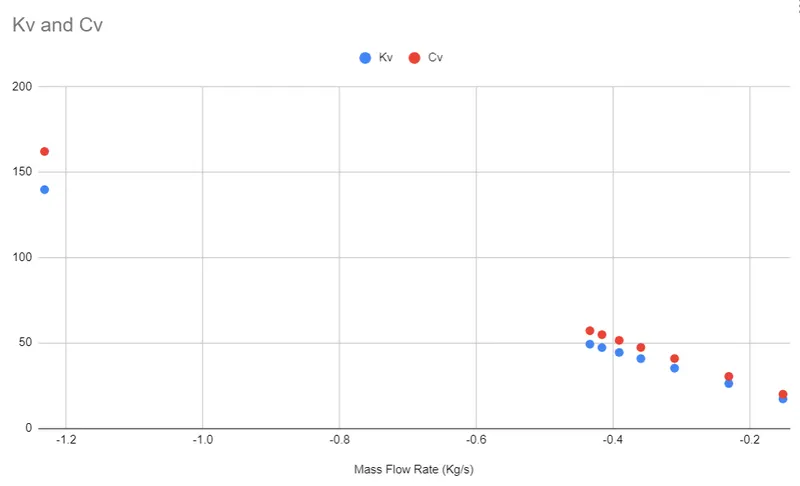
Graph of Cv vs Kv vs Outlet Mass Flow Rate
CONCLUSION
The relationship observed between the valve lift, mass flow rates, and flow coefficients (Cv and Kv) indicates the direct influence of the valve opening on the fluid flow characteristics. As the valve lift increases, the flow area also increases, allowing more fluid to pass through the valve. This leads to higher mass flow rates, as reflected in the data.
The increase in mass flow rates is accompanied by higher Cv and Kv values, indicating improved flow capacities. A larger valve opening results in reduced flow resistance, allowing for higher flow rates at a given pressure difference.
For Project File, Click here