Week 9 - Parametric study on Gate valve.
AIM:-
Perform a parametric study on the gate valve simulating by setting the opening from 10% to 80%.
OBJECTIVE:-
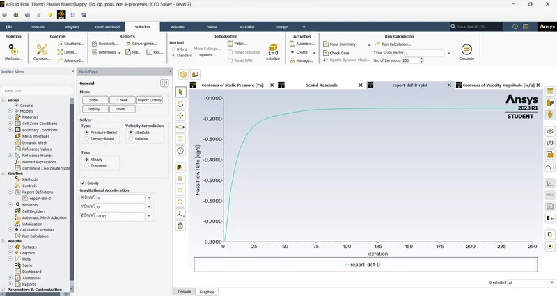
- Obtain the mass flow rates at the outlet for each design point.
- Calculate the flow coefficient and flow factor for each opening and plot the graph.
- Discuss the results of the mass flow rate and flow coefficient.
THEORY:-
- A gate valve opens by lifting a gate out of the path of the fluid.Gate valves required very little space along the pipe axis and hardly restrict the flow of fluid when the gate is fully opened.The gate faces can be parallel but are most commonly wedge shaped.
- Gate valves are used to shut off the flow of liquids rather than for flow regulation. When fully open, the typical gate valve has no obstruction in the flow path, resulting in very low flow resistance. The size of the open flow path generally varies in a nonlinear manner as the gate is moved. This means that the flow rate does not change evenly with stem travel. Depending on the construction, a partially open gate can vibrate from the fluid flow.
- Gate valves are mostly used with larger pipe diameters (from 2" to the largest pipelines) since they are less complex to construct than other types of valves in large sizes.
- Gate valves without an extra sealing ring on the gate or the seat are used in applications where minor leaking of the valve is not an issue, such as heating circuits or sewer pipes.
- Generally in pipelines with high pressure, the gate valve opening can be quite difficult due to the high force exerted on the gate. So they are generally connected with a smaller bypass valve to release the pressure and then they are operated.
- One of the best ways to get value out of your simulation is to do parametric analysis. With very little marginal work a completed model can be parameterized to simulate scenarios limited only by your computational time and resources.
- As you move forward in your design, you can assess the impact that changing certain parameters can have on the design. The parameters can include dimensional parameters. Parametric studies allow you to nominate parameters for evaluation, define the parameter range, specify the design constraints, and analyze the results of each parameter variation.
SOLUTION:-
GEOMETRY:-
- Import the geometry in the spaceclaim from the file.
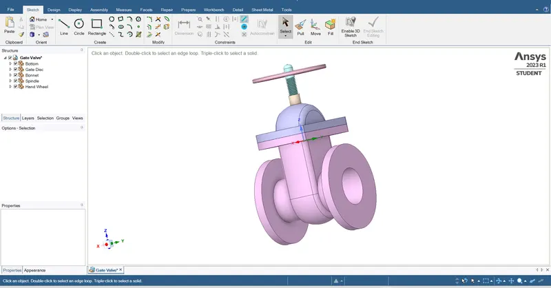
- Hide the bottom to and select move option and set the different values which given in the statement 10 mm 20mm 30mm 40mm 50mm 60mm 70mm 80mm.
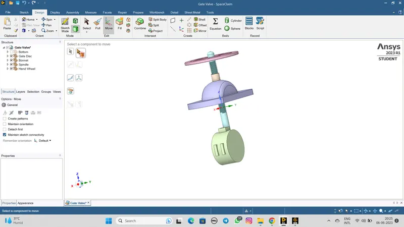
- Then hide all the face model like bottom,gate disc, bonnet,spindle,hand wheel.
- Now extract the volume using volume extract in prepare at 800mm size from both side.
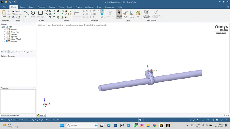
- After this process start the mesh process
MESH:-
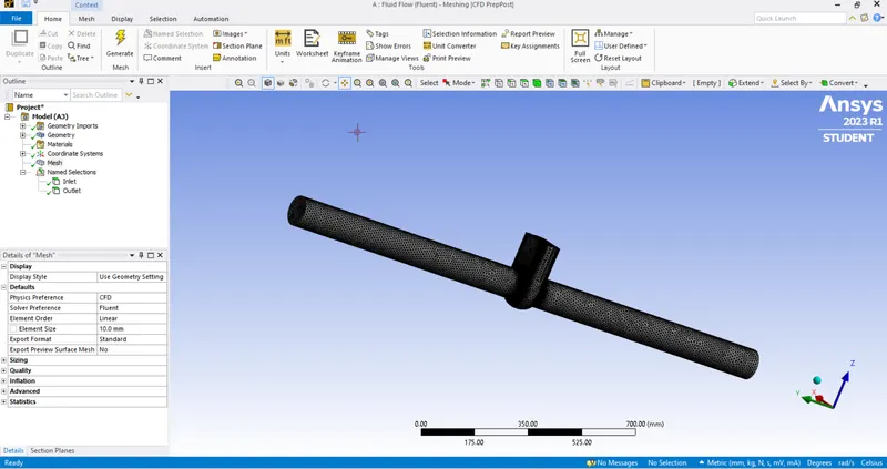
- Start the mesh process with the change the element size 10mm and then countinue change element size for different values.
- Select face and give the name inlet and outlet.
SETUP:-
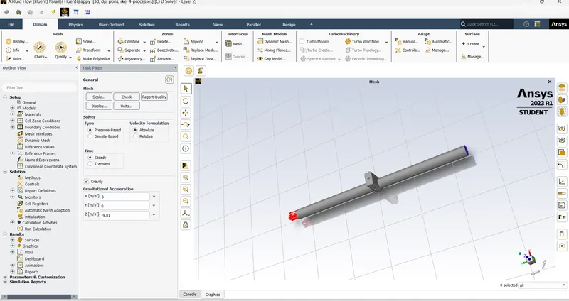
- Solver type : pressure based
- Time steadt : steady
- Enable gravity with the -9.81m/s^2 on z-axis
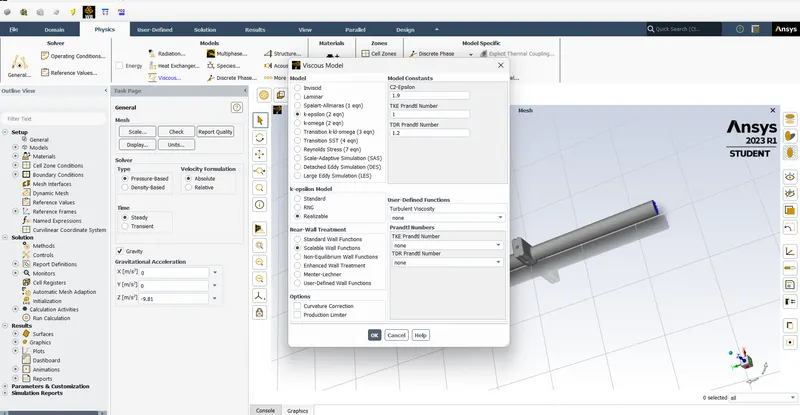
- Turbulence model: K-epsillon>realizable>scaled wall function
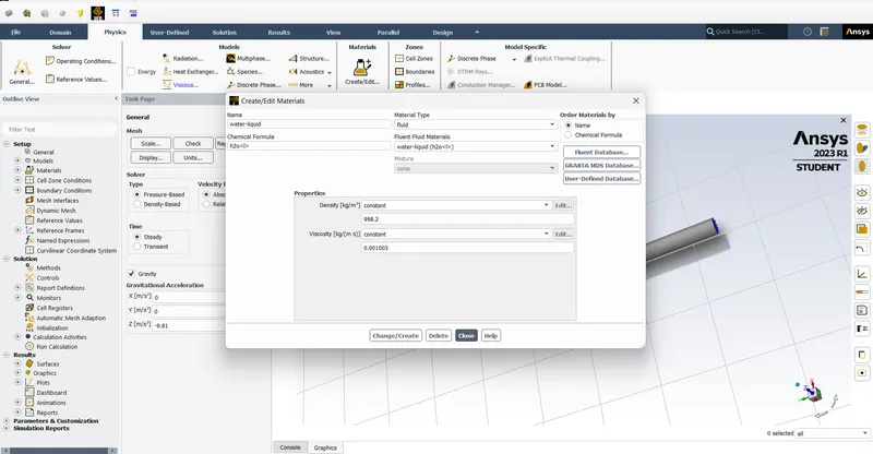
- Material : water
- Boundary condition for inlet>preassure inlet=guage total pressure 10 pascal
- Outlet>0 pascal
- Set solution method with second order upwind
- Then initialize with standard method
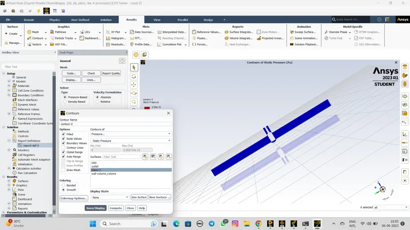
- Select contours>new>select plane>countors of pressure and velocity
Pressure :-
Velocity:-
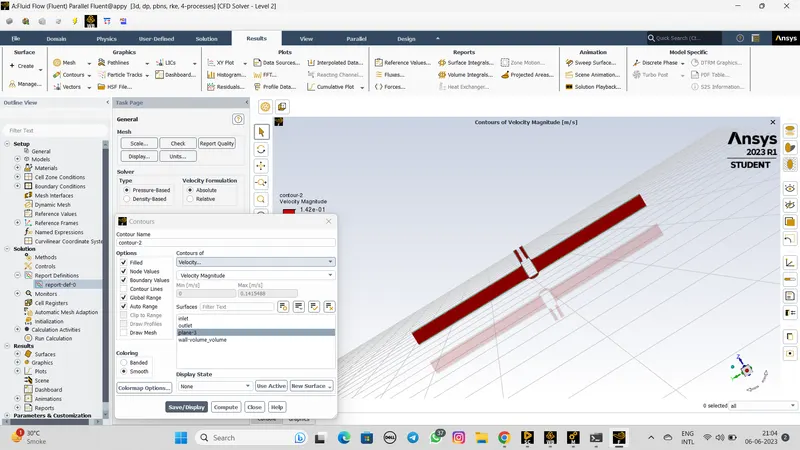
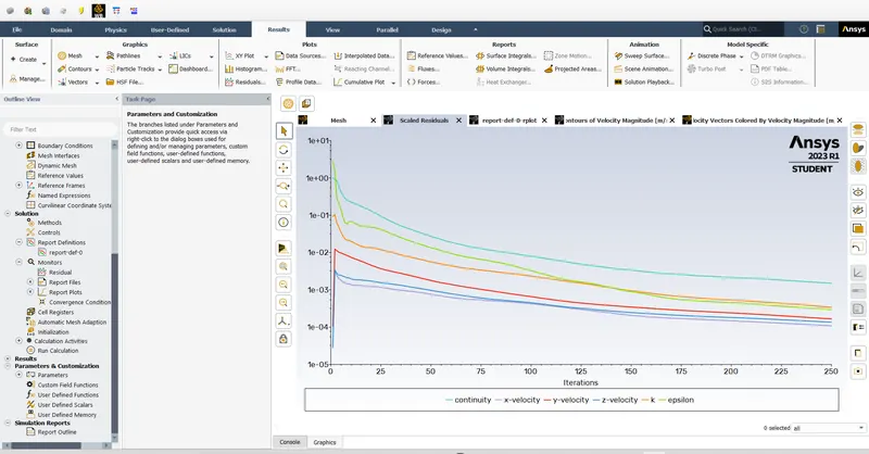
- After this all procedure run for the 250 iterations.
RESULT:-
Case 1:- Lift 10mm
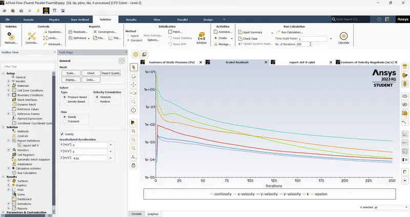
Residual plot:-
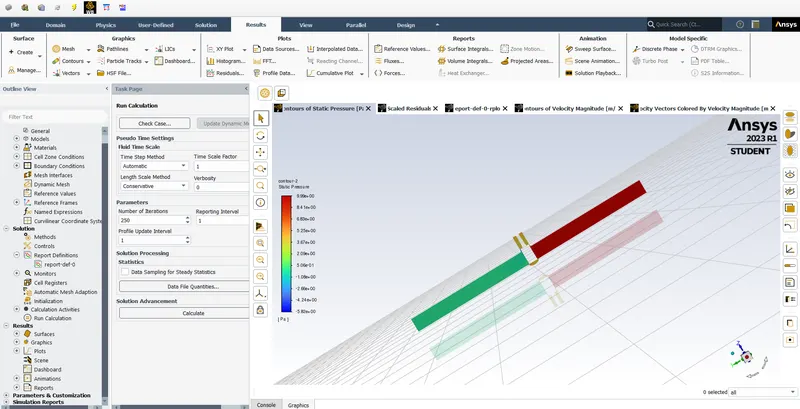
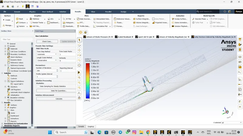
Velocity:-
- Stream line of velocity:-
Case 2:- Lift 20mm
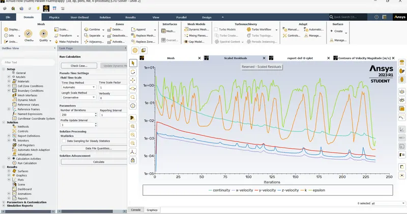
Residual plot:-
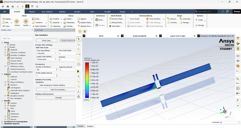
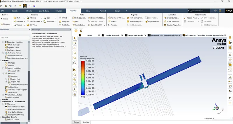
Velocity Magnitude:-
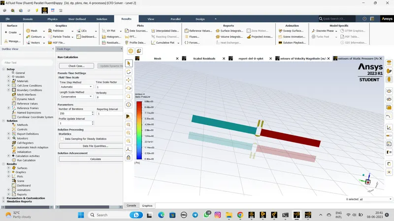
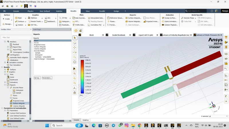
Pressure:-
Velocity plane:-
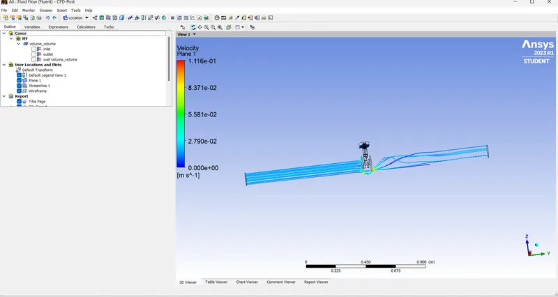
Case 3:- Lift 30mm
Residual plot:-
Velocity Magnitude:-
Pressure:-
Conclusion:-
- The parametric study of gate valve indicates the increase in mass flow rate at the outlet section
- The graphical plot for mass flow rate and flow coefficient also support the simulation results.