Week 9 - Parametric study on Gate valve.
AIM:To perform a parametric study on the gate valve simulation.
Objectives:
- To perform a parametric study on the gate valve simulation by setting the opening from 10 % to 80%.
- To Obtain the mass flow rates at the outlet for each design point.
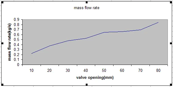
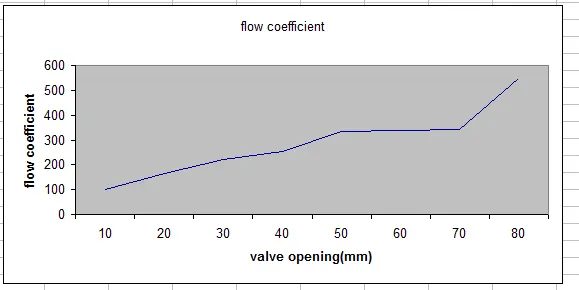
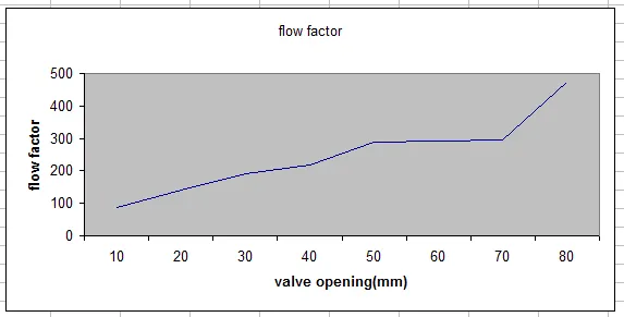
- To Calculate the flow coefficient and flow factor for each opening and plot the graph.
- To Discuss the results of the mass flow rate and flow coefficient.
Theory:
A gate valve, also called sluice valve, often installed in a pipe fitting, opens by lifting a barrier called gate out of the path of the fluid. Gate valves require very little space along the pipe axis and hardly restrict the flow of fluid when the gate is fully opened. The gate faces can be parallel but are most commonly wedge-shaped.
Gate valves are used to shut off the flow of liquids rather than for flow regulation. When fully open, the typical gate valve has no obstruction in the flow path, resulting in very low flow resistance.
Geometry:
Gate Valve:
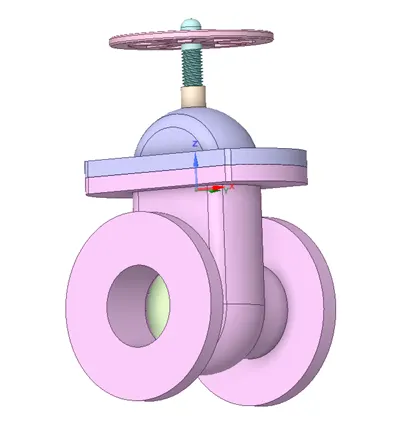
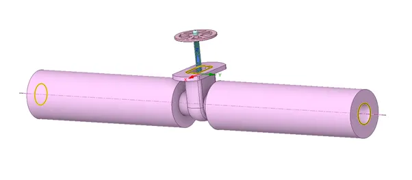
To provide lift in gate disk enable MOVE in Desigh tab and then select component .Now move the disk in upward direction using the new axis appeared and initial value of 10mm lift is provided.
To paramatize this enable create parameter in Group section.
Pull bottom using PULL option in Design tab and enter value of 800 for both side of bottom component
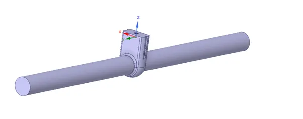
Volume is extracted using Extract volume option in Prepare tab
Extracted Volume:
Solver and settings:
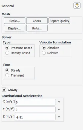
Steady state simulation is needed with gravity enabld
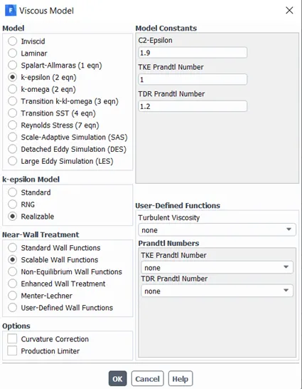
Realizable k-eosilon model with scalable wall function is used since near wall properties do not play much role in present case.
Viscous Model:
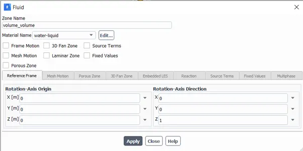
Material:
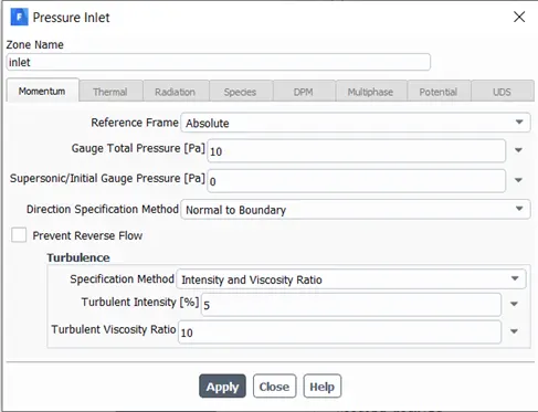
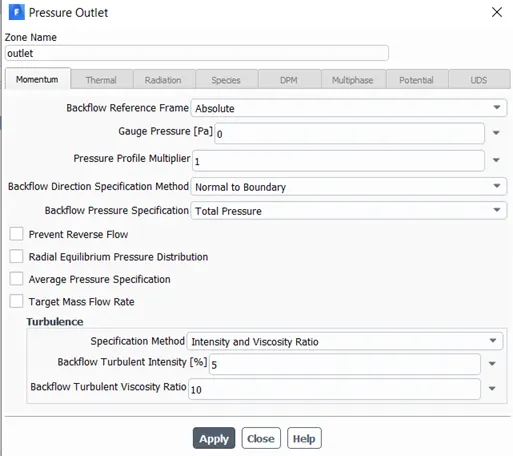
Boundary Conditions:
Pressure inlet:
Pressure outlet:
Surface Definition:
1-
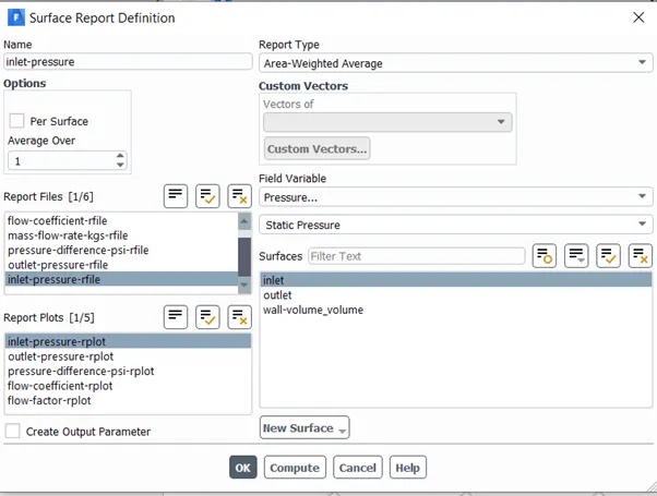
2-
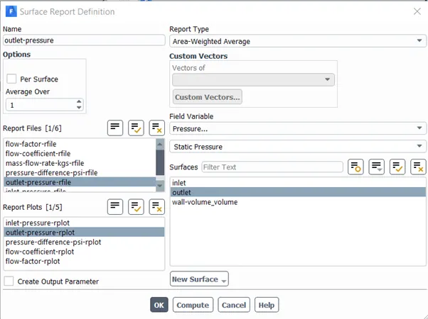
3-
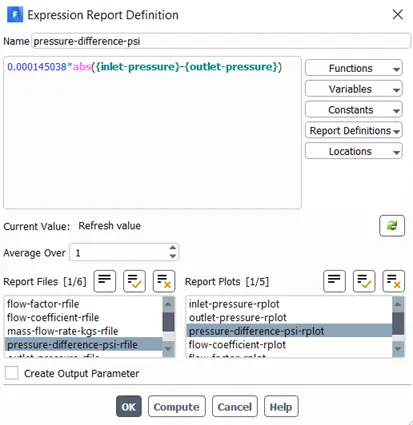
4-
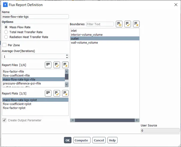
5-
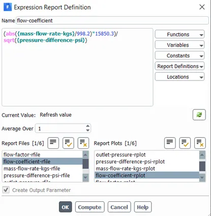
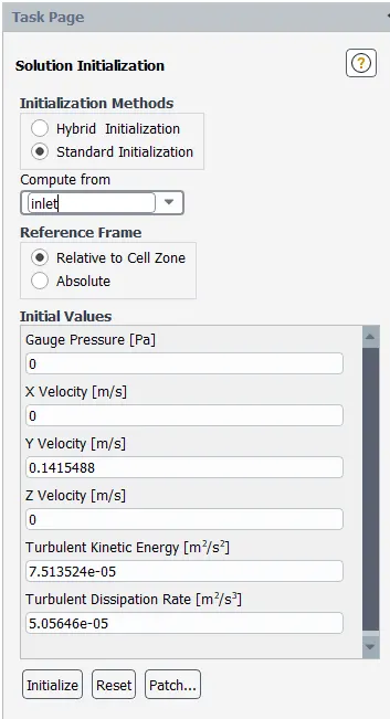
Flow – coefficient:
Flow coefficient is calculated using the expression:
Cv=Q⋅√SG/ΔP
- Where, Q is Volumetric flow rate in Gallons per minute.
- ΔP">ΔP is the pressure difference in psi.
- Mass flow rate has been converted to Gallon par minute using multiplication factor (15850.3/998.2) on mass flow rate(Kg/s)
- SG is the specific gravity of fluid flowing, in this case its water, so its value is 1.
Flow Factor :
Kv=0.862⋅Cv">Kv=0.862⋅Cv
Where,
Kv is the flow factor
Cv is the flow coefficient
Parametric Study:
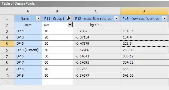
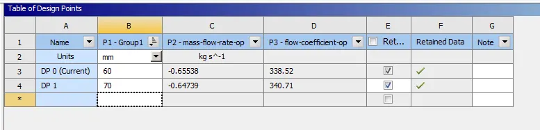
| valve opening(%) | mass flow rate(kg/s) | flow ciefficient | flow factor |
| 10 | 0.2387 | 101.94 | 87.87 |
| 20 | 0.37154 | 164.4 | 141.71 |
| 30 | 0.47879 | 221.5 | 190.93 |
| 40 | 0.52786 | 253.98 | 218.88 |
| 50 | 0.64641 | 335.12 | 288.87 |
| 60 | 0.65538 | 338.52 | 291.8 |
| 70 | 0.69739 | 340.71 | 293.69 |
| 80 | 0.84577 | 548.66 | 472.85 |
Plots:
Mass flow rate:
Flow coefficient:
Flow factor:
Inferences:
As from the graph it can be choncluded that mass flow rate increses with the increase in valve opening perecentage.
Flow coefficient and flow fator also increases with increase in valve opening