Week 9 - Parametric study on Gate valve.
AIM:
Perform a parametric study on the gate valve simulation by setting the opening from 10 % to 80%.
- Obtain the mass flow rates at the outlet for each design point.
- Calculate the flow coefficient and flow factor for each opening and plot the graph.
- Discuss the results of the mass flow rate and flow coefficient.
Gate Valve:
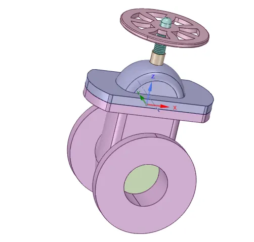
- Gate valves work by inserting a rectangular gate or wedge into the path of a flowing fluid. They are operated by a threaded stem that connects the actuator (generally a hand wheel or motor) to the stem of the gate. If the valve has a rising stem its position can be seen just by looking at the position of the stem. A gate valve is used to control the fluid flow by lifting and descending the gate. A gate distinct feature is to provide an unobstructed passageway, which includes minimal pressure loss over the valve.
- When the gate is fully opened there is no restriction to the flow hence the pressure drop is low comparatively. Generally, the gate valve are fully closed or fully open as the partially opened valves may experience vibration which may lead to excessive wear. A gate valve's main component is the body, seat, gate, stem, bonnet, and actuator. the primary mechanism is straight forward where the handwheel is rotated to move the gate up and down via threads
Geometry-Setup.
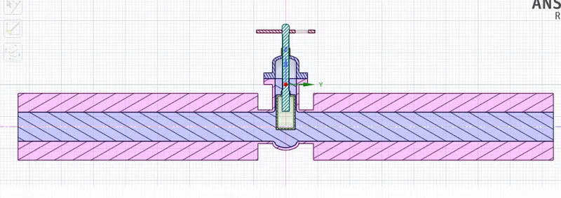
- Import the model from the problem by opening the space claim.
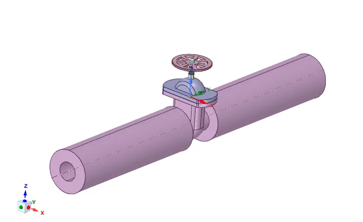
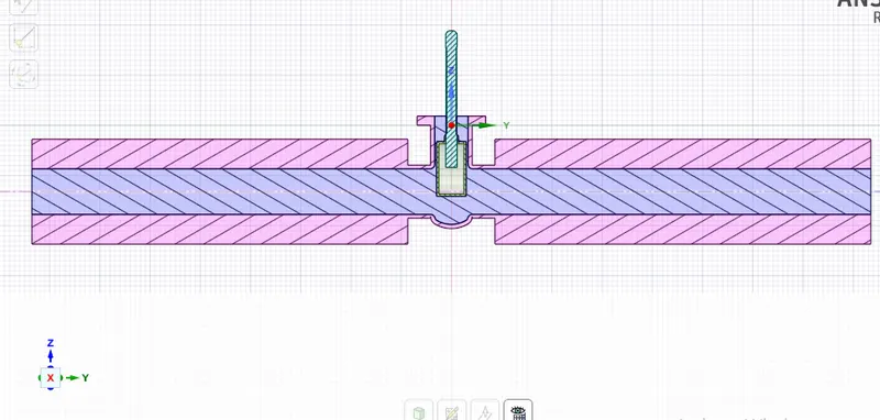
- Extend the both pipes upto 800mm using pull option.
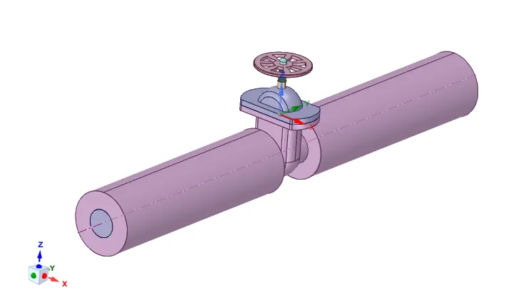
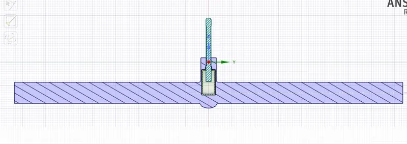
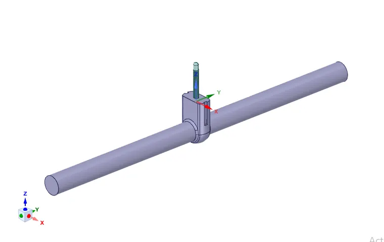
- Create the fluid volume by selecting the edges with the help of volume extract option in spaceclaim.
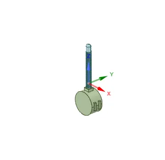
- Then by using the Move option move the spindle and gate disc together and set as parameter in the group by using create parameter.
- All the components other than volume apply the supress for physics.
Meshing.
- Then the geomentry is opened in the mesh module of ansys fluent and give generate mesh with an element size of 10mm.
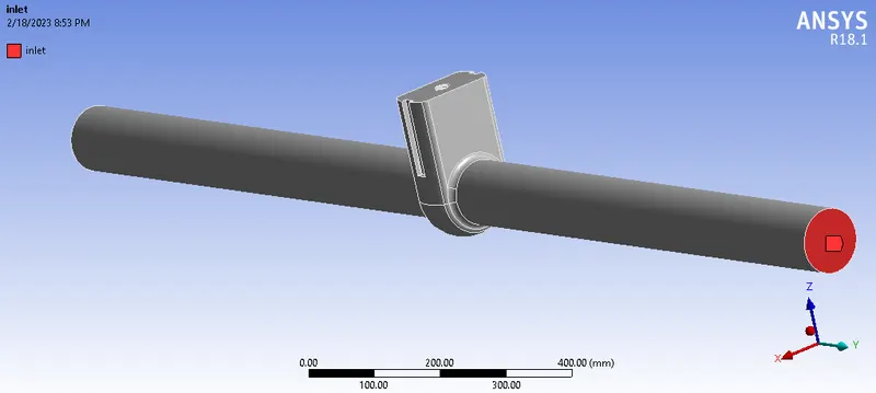
- After the mesh is generated, provide named selections as inlet and outlet on the meshed geometry.
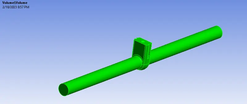
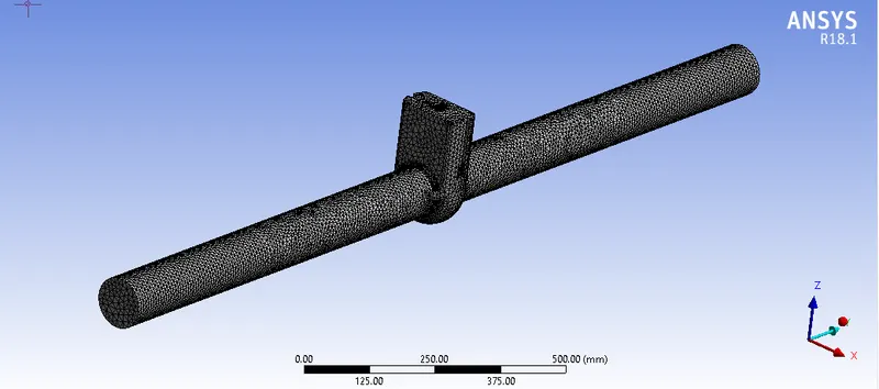

Named Selections.
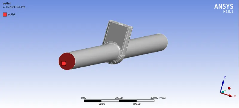
Fluent- Set up.
- After the mesh is generated ,open the set up module and here we have to set the condition like physics, boundery conditions, type of analysics, Solution setups and the outupts.
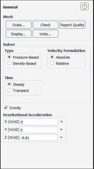
- Enable the steady state solver, Pressure based is used because the velocity of air is low ( less than 0.3 of mach number ) and enable gravity with Z axis as -9.81m/s^2.
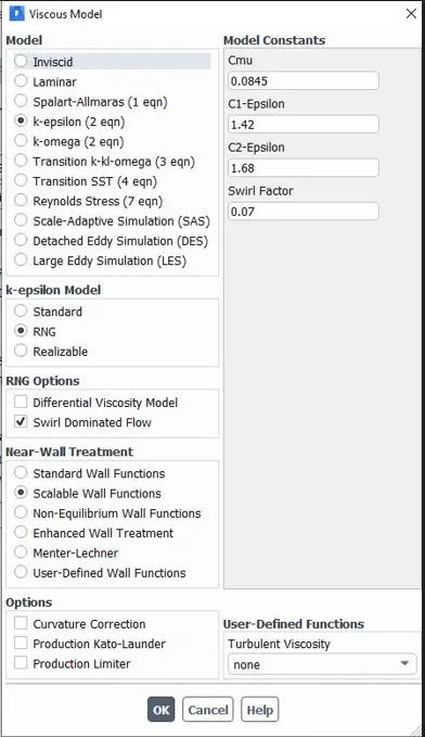
- K-epcelon model is used by opening the Viscous option in the physics.
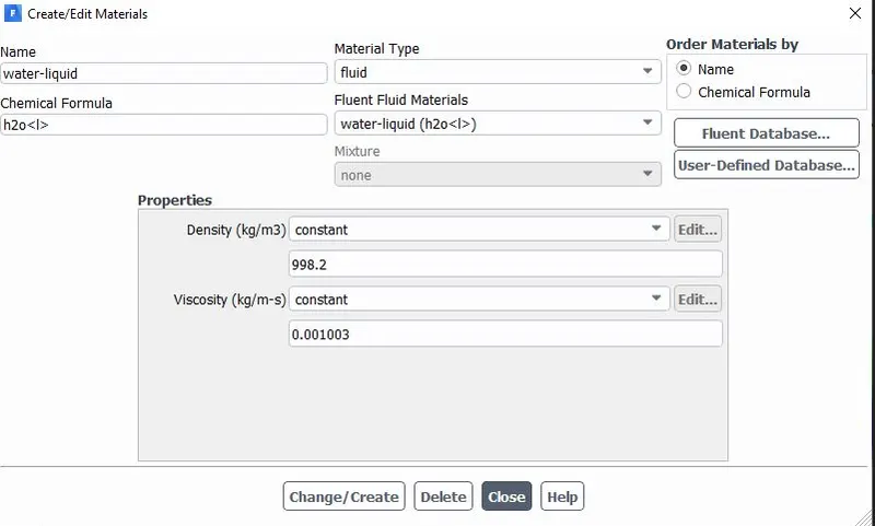
- New material as water (H2O-liquid) from the fluid database in the material selection is selected and used for the simulation and delete the air.
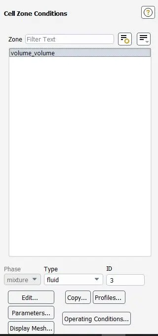
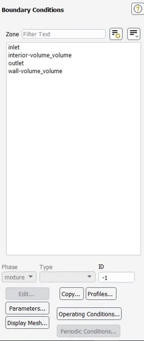
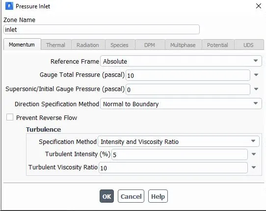
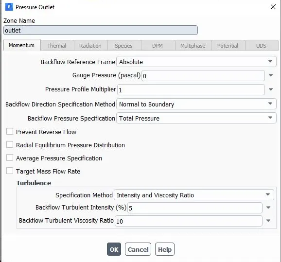
- Then setup the bounadry conditions with inlet as pressure inlet with a gauge pressure of 10pascal and the outlet as pressure outlet with a gauge pressure of 0pa.
- Then create the suitable reports from report definitions.
- Initialize with hybrid initialization and set the no of iterations.
Cases for parametrizing the gate valve lift.
Case-1-10mm lift.
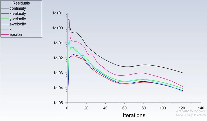
Residual:
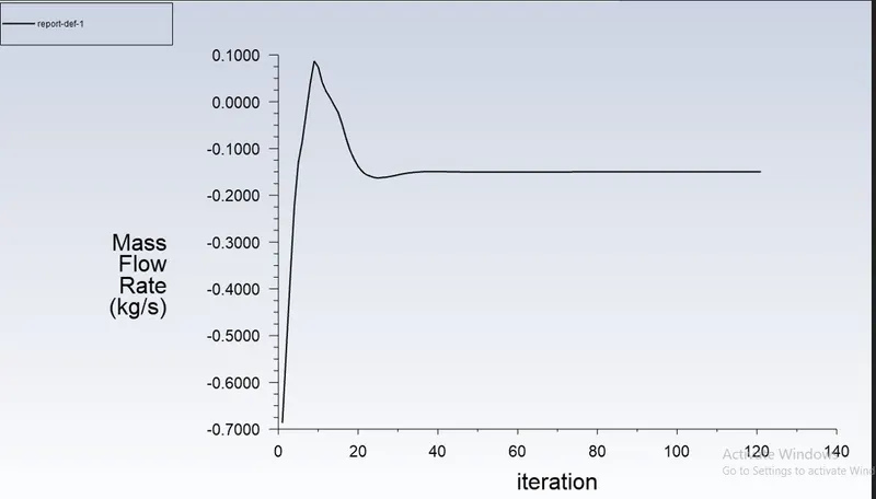
Mass flow rate-plot
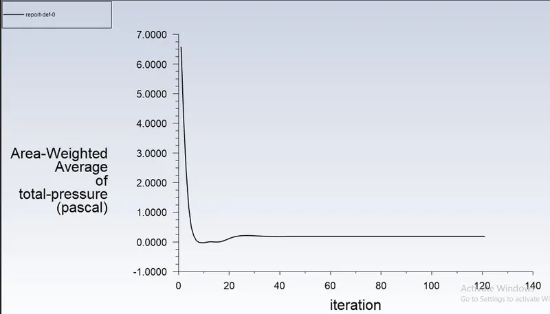
Area weighted average of pressure at outlet:
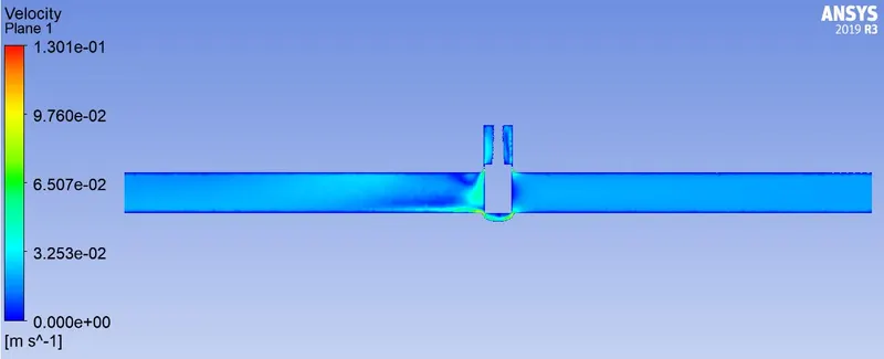
Velocity contour:
Case-2-20mm lift.
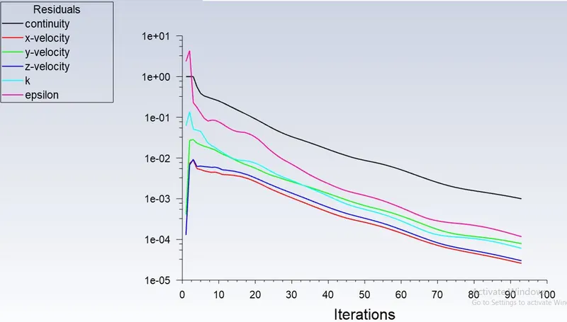
Residual:
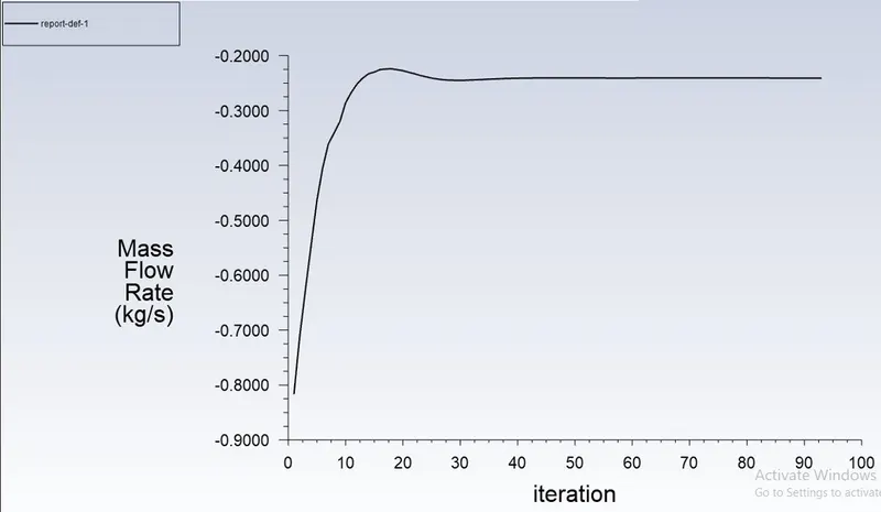
Mass flow rate-plot
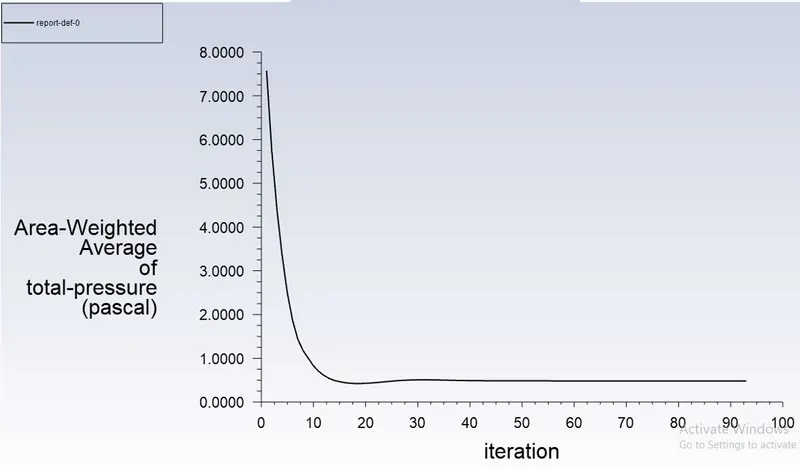
Area weighted average of pressure at outlet:
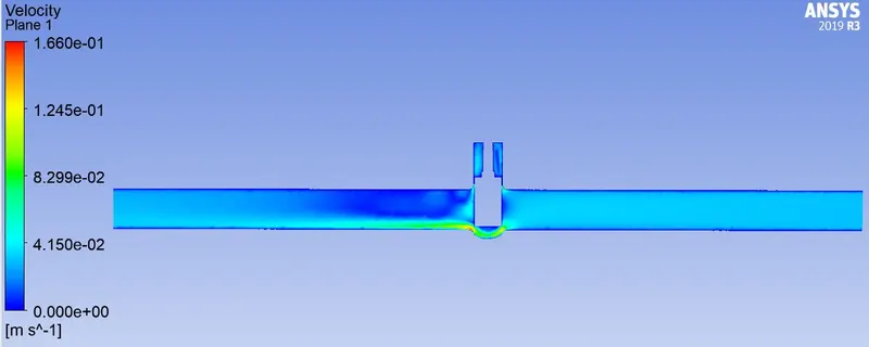
Velocity contour:
Case-3-30mm lift.
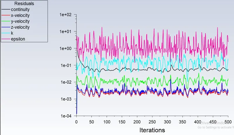
Residual:
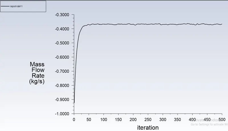
Mass flow rate-plot
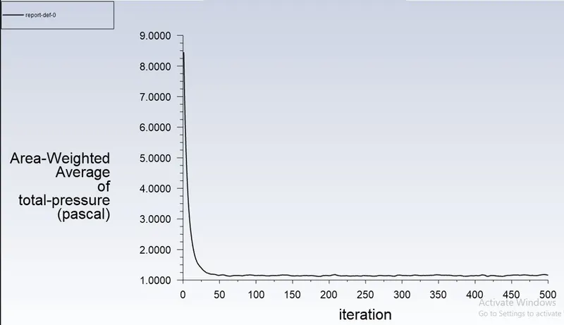
Area weighted average of pressure at outlet:
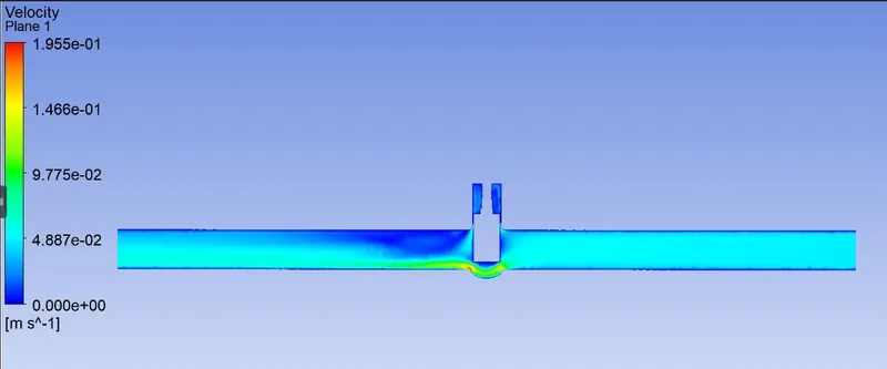
Velocity contour:
Case-4-40mm lift.
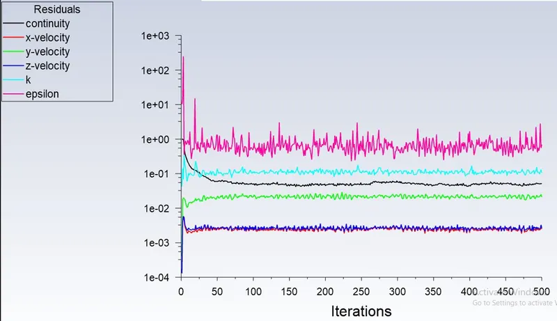
Residual:
Mass flow rate-plot
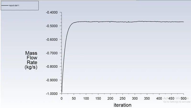
Area weighted average of pressure at outlet:
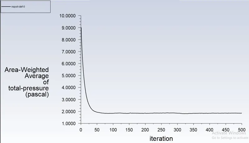
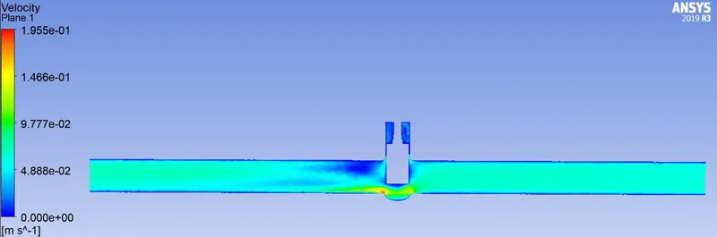
Velocity contour:
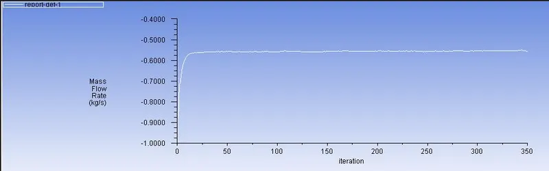
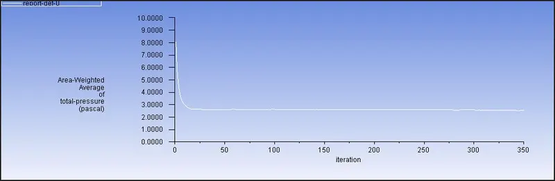
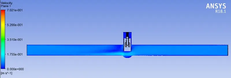
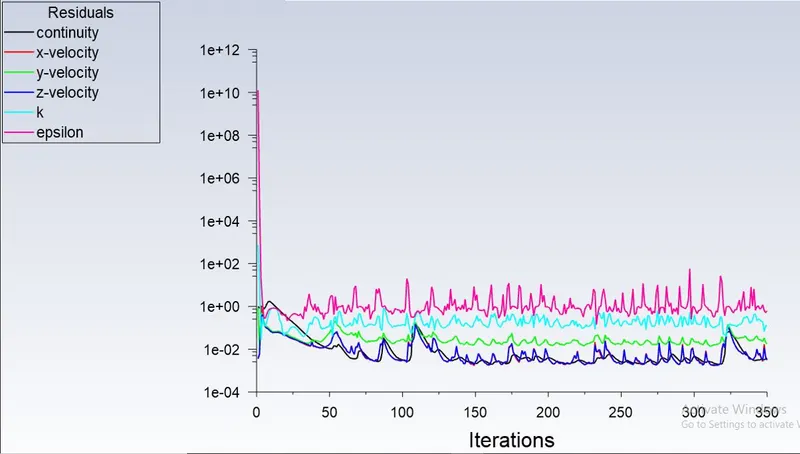
Case-5-50mm lift.(Because of the availability of system, this case has to be run in another version of ansys in another system).
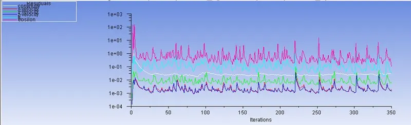
Residual:
Mass flow rate-plot.
Area weighted average of pressure at outlet:
Velocity contour:
Case-6-60mm lift.
Residual:
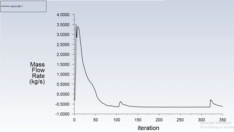
Mass flow rate-plot.
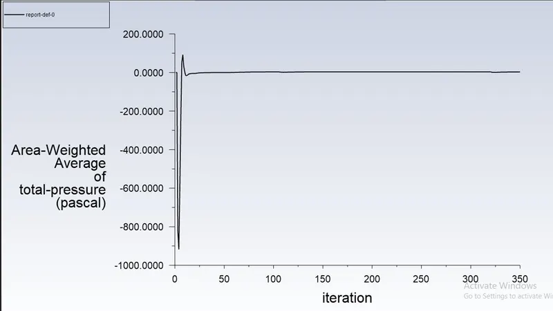
Area weighted average of pressure at outlet:
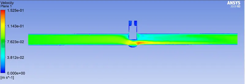
Velocity contour:
Case-7-70mm lift.
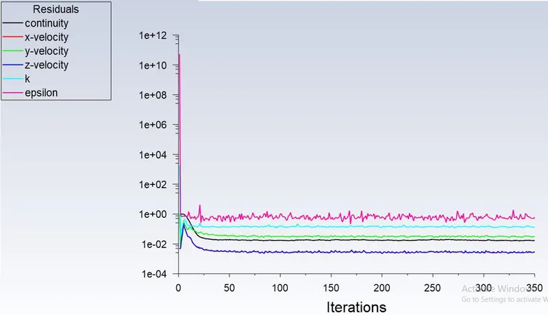
Residual:
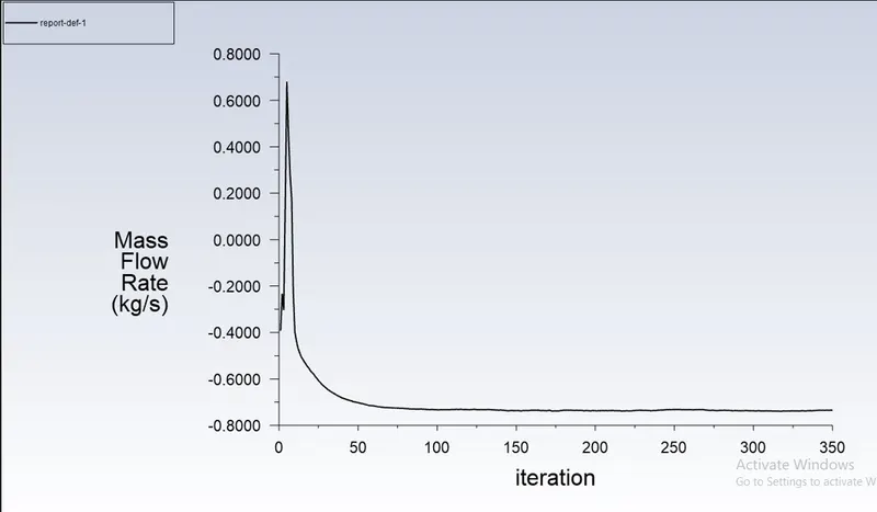
Mass flow rate-plot.
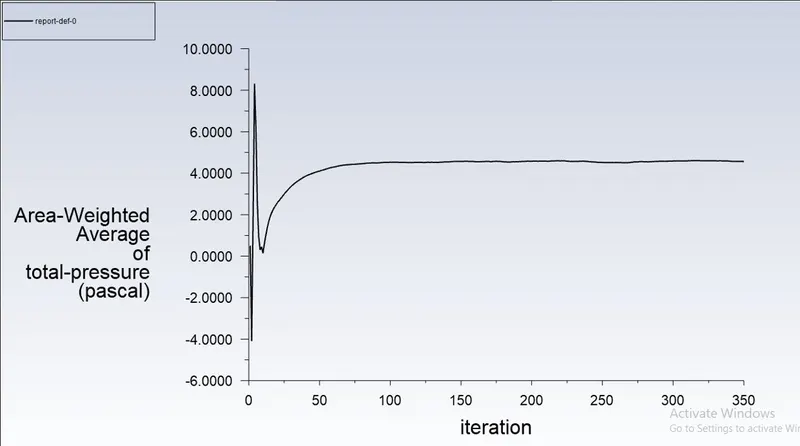
Area weighted average of pressure at outlet:
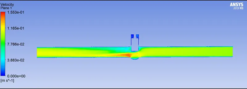
Velocity contour:
Case-8-80mm lift.
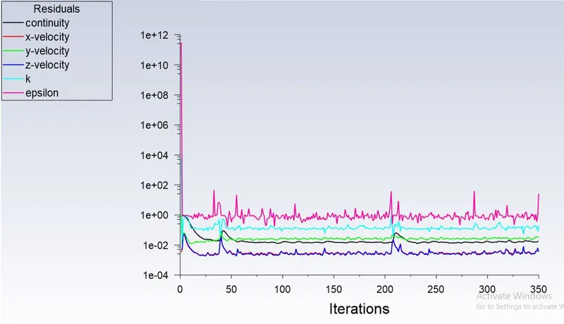
Residual:
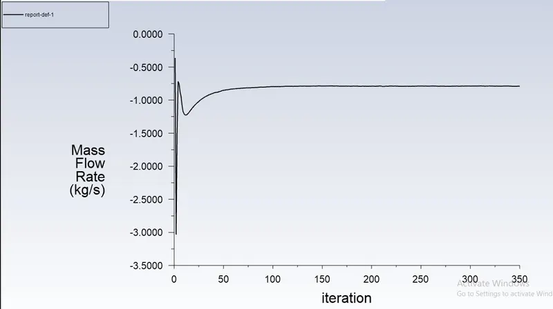
Mass flow rate-plot.
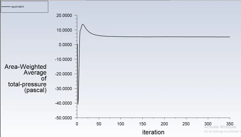
Area weighted average of pressure at outlet:
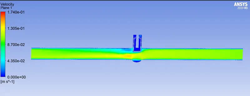
Velocity contour:
Flow factor & Flow Coefficient
Flow Coefficient
- When the flow goes through a valve or any other restricting device it loses some energy.
- The flow coefficient is a designing factor which relates head drop (Δh) or pressure drop (ΔP) across the valve with the flow rate (Q).
- Kv=0.865⋅Cv
- Cv = Kv/0.865
Flow Factor
- Kv = Q * √ (SG/ΔP)
| Cases | Lift(mm) | Mass flow rate(Kg/s) | Pressure at outlet(Pa) | Flow factor(Kv) | Flow coefficient(Cv) |
| 1 | 10 | 0.14996055 | 0.18876086 | 54.50 | 63.00 |
| 2 | 20 | 0.24084941 | 0.48319444 | 88.87 | 102.75 |
| 3 | 30 | 0.36643729 | 1.1592511 | 140.29 | 162.19 |
| 4 | 40 | 0.47224876 | 1.8648175 | 188.49 | 217.90 |
| 5 | 50 | 0.55605189 | 2.5714364 | 232.25 | 268.50 |
| 6 | 60 | 0.61859763 | 3.1547854 | 269.16 | 311.17 |
| 7 | 70 | 0.73413944 | 4.563345 | 358.43 | 414.38 |
| 8 | 80 | 0.79003674 | 5.2005692 | 410.53 | 474.61 |
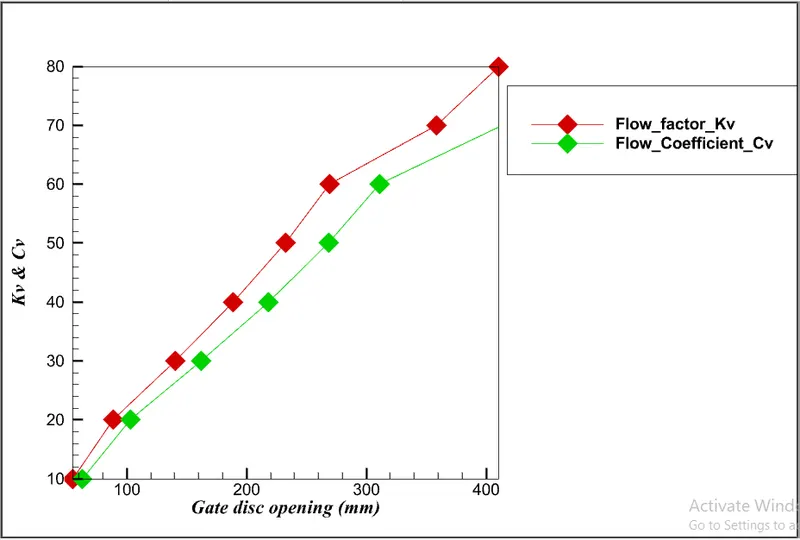
TREND SHOWING THE FLOW AND FACTOR COEFFICIENTS WITH VALVE OPEN
Conclusion & Inference
- we can observe that as the opening of the Gate Valve or Lift of the Gate Disc increases the mass flow rate increases.
- With increase in mass flow rate, there is an increment in Flow Coefficient as well as the flow factor.
- From the tabular data and plot, it can be concluded that the mass flow rate, flow coefficient, and flow factor varies linearly with gate disc opening.