Week 9 - Parametric study on Gate valve.
AIM: To perform a parametric study on a gate valve simulation by setting the opening from 10 % to 80%.
OBJECTIVE:
1.To simulate the flow of fluid through a gate valve.
2.To obtain the mass flow rates at the outlet for each design point.
3.To calculate the flow coefficient and flow factor for each opening and plot the graph.
4.Discuss the results of the mass flow rate and flow coefficient.
DESCRIPTION:
A Gate valve also known as sluice valve is a valve that opens by lifting a barrier (gate) out of the path of the fluid. Gate valves require very little space along the pipe axis and hardly restict the flow of fluid when the gate is fully opened. The gate faces can be parallel but are most commonly wedge-shaped in order to be able to apply the pressure on the sealing surface.
PARAMETRIC STUDY:-
parametric study is very helpful when we need results for different cases with change of a few factors in the original case we can enter these input and output as parameters
A parametric study requires the following
1.Design objective is set to parametric dimensions.
2.Parameters nominated for use in the simulation
3.Design criteria specified
4.Various configurations generated.
FOW COEFFICIENT
The flow coefficient of a device is relative measure of its efficiency at allowing fluid flow.It describes the relationship between the pressure drop across an orifice valve or other assembly and the corresponding flow rate. Mathematically the flow coefficient or flow capacity rating Cv can be expressed as
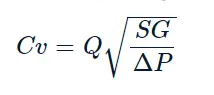
Where Q is the rate of flow (gallons per minute)
SG is the specific gravity of fluid (for water =1)
is the pressure drop across the valve expressed in psi.
10 Pa = 0.00145038 psi
The use of flow coefficient offers a standard method of comparing valve capacities and sizing valves for specific applications that are widely accepted by the industry.The general definition of the flow coefficient can be expanded into equations modelling the flow of liquids, gases and steam using the discharge coefficient.
FLOW FACTOR:
The metric equivalent factor Kv commonly used in europe and Aisa is calculated using metric units
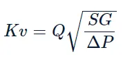
Kv can be calculated from Cv using the equation as given below
Kv = 0.865Cv
The Kv factor of the valve indicates, The water flow m3/h at a pressure drop across the valve of 1kgf/cm2 when the valve is completely open.
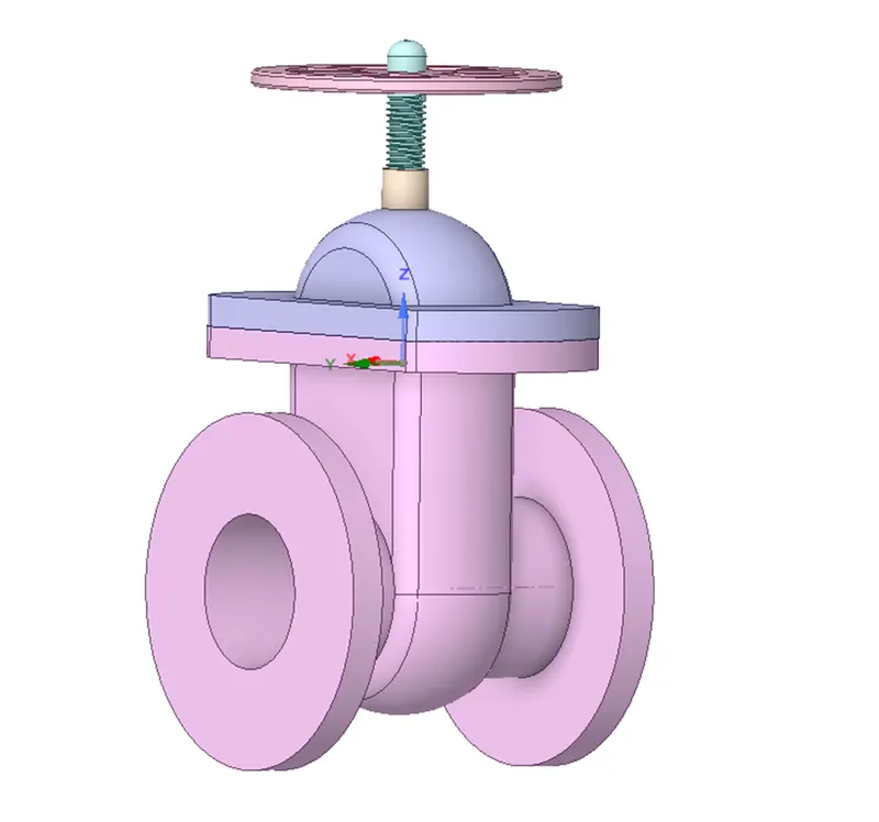
Geometry-
load the model into space claim
using pull tool er can extrude the sides of valves to length 800mm
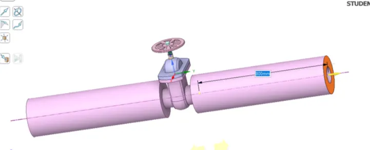
now we can can do volume extract by selsecting all the edges
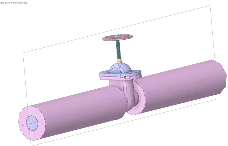
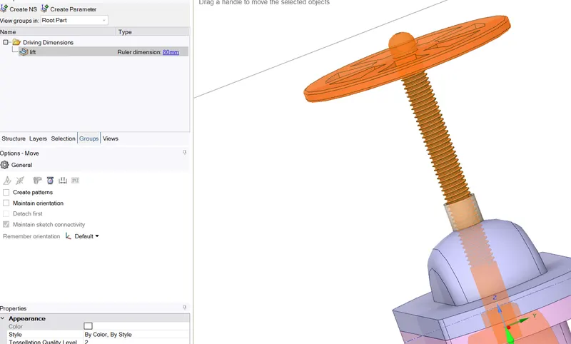
now we need to create the lift of valve as a input parameter first we can select all the parts of valve and using the move command we can move it by 10 mm while using move option me can go to groups and click on create parameters
we neet to update our volume we can r click on volume than click on update
Meshing-
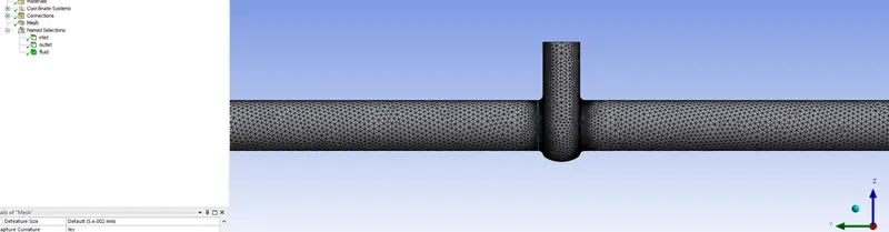
using 10mm element size
element 1.8 lac
create the require named selections inlet,outlet,fluid
Setup-
K epsilon RNG model
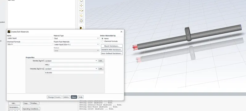
material = water
boundary conditions
inlet pressure 10 pa (Gauge Pressure)
outlet 0 pa (Gauge Pressure)
create a report of masss flow rate and tick the option set as output parameter
After that we can the simulation for 1000 iterations
now we can go to work bench and we will se a parameter option
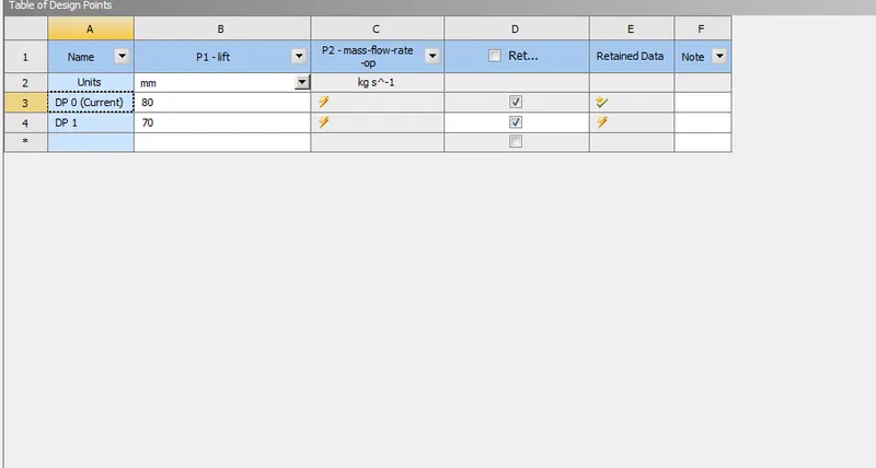
here we can enter value of lift for each case and we can get the result value
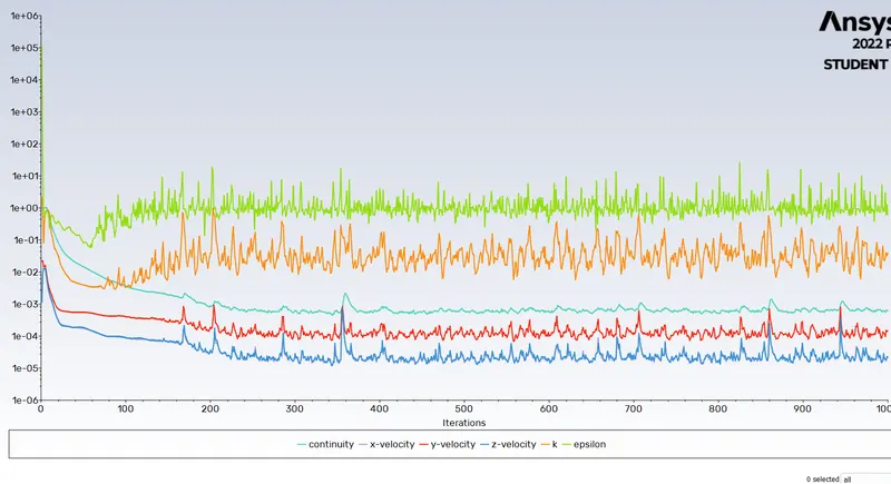
case 1
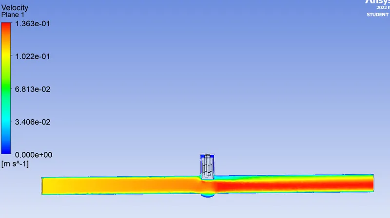
lift =80m
residual plot-
velocity contour-
Case 2
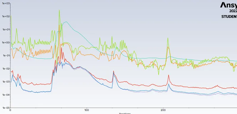
lift 70 mm
residual plot-
Velocity contour-
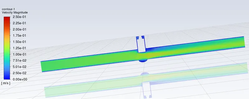
Case 3-
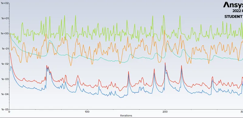
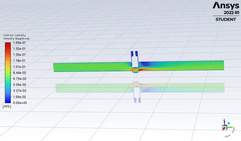
lift 60mm
residual plot-
vel plot-
Case 4 -
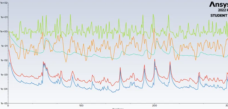
lift 50mm
residual value-
velocty contour-
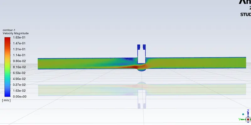
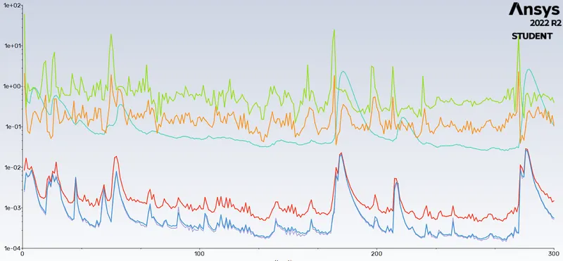
Case 5 lift 40mm
residual plot-
velocity contour-
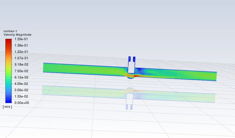
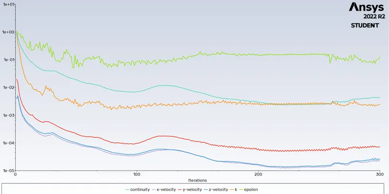
case 6 lift 30mm
residual plot-
vel contour-
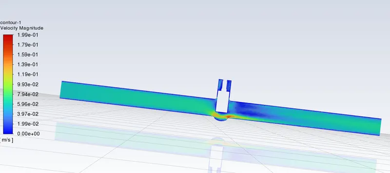
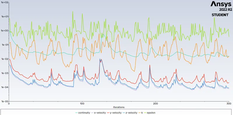
case 7 20 mm lift-
residual plot-
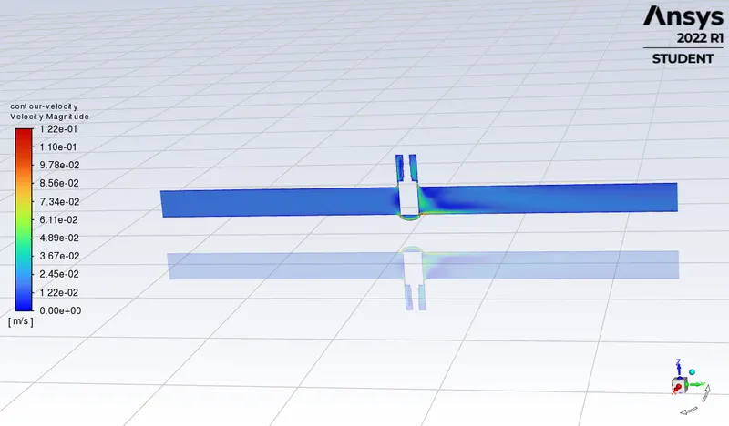
velocity contour-
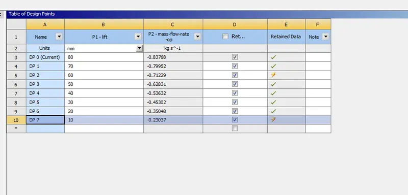
as we can see the final results-
calcualtion of flow factor(KV) and flow coeff(CV)
Flow Coefficient, Cv=Kv0.865">Cv=Kv/0.865
Cv=Kv0.865">FINAL RESULTS-
| Sno | name | LIFT(MM) | MASS FLOW RATE(KG S-1) | FLOW FACTOR | FLOW COEFF |
| 1 | DP1 | 80 | 0.8339 | 0.263737553 | 0.304898905202312 |
| 2 | DP2 | 70 | 0.7995 | 0.252857865 | 0.292321231213873 |
| 3 | DP3 | 60 | 0.7119 | 0.225152613 | 0.260292038150289 |
| 4 | DP4 | 50 | 0.62831 | 0.1987156037 | 0.229729021618497 |
| 5 | DP5 | 40 | 0.5362 | 0.169583974 | 0.19605083699422 |
| 6 | DP6 | 30 | 0.45302 | 0.1432766354 | 0.165637728786127 |
| 7 | DP7 | 20 | 0.35048 | 0.1108463096 | 0.12814602265896 |
| 8 | DP8 | 10 | 0.23037 | 0.0728591199 | 0.084230196416185 |
CONCLUSION:
Mass flow rate gradually increases as the lift of gate disc is increased.
The variation of flow coefficient and flow factor with the opening of the valve is studied by using parametric method.
Parametric study is time reducing option when studying the effects of changes of certain parameters of a system