Week 9 - Parametric study on Gate valve.
Aim
To perform a parametric study on the gate valve simulation by setting the opening from 10 % to 80%.
Introduction
A gate valve is generally used to completely shut off fluid flow or, in the fully open position, provide full flow in a pipeline. Thus it is used either in the fully closed or fully open positions. A gate valve consists of a valve body, seat and disc, a spindle, gland, and a wheel for operating the valve. The seat and the gate together perform the function of shutting off the flow of fluid. Gate valves are generally not suitable for regulating flow or pressure or operating in a partially open condition. For this service, a plug valve or a control valve should be used.
solving and modeling approch
- Obtain the mass flow rates at the outlet for each design point.
- Calculate the flow coefficient and flow factor for each opening and plot the graph.
- Discuss the results of the mass flow rate and flow coefficient.
Pre-processing and solver setting
Geometry
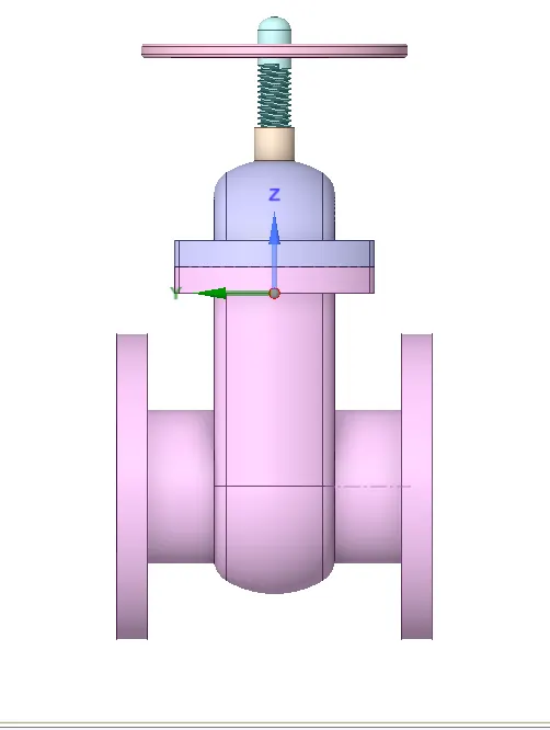
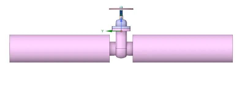
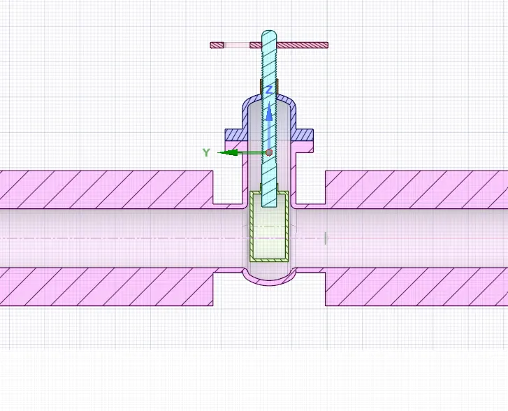
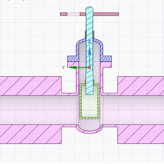
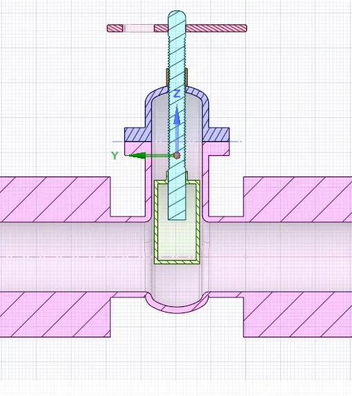
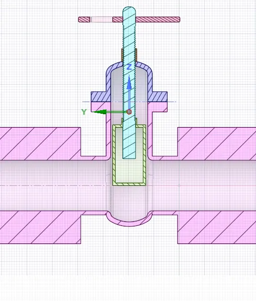
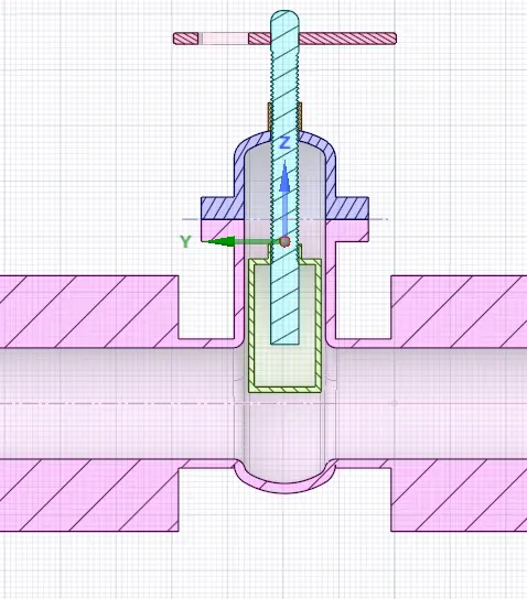
Open the geometry with space claim the geometry representing only the gate valve extude the length of 800mm on the pipe on both side for the fluid flow using with pull option
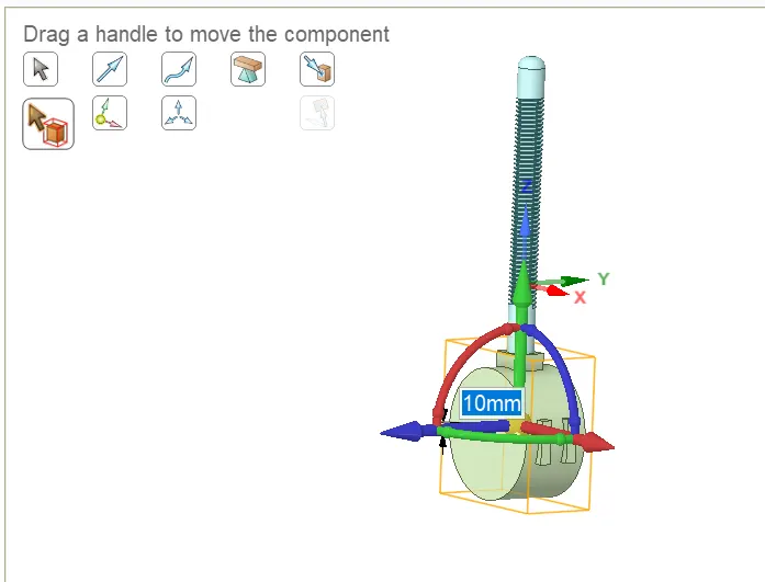
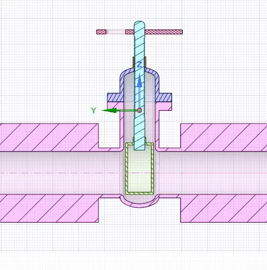
in this case the vavle must lifted to differet heightes there is tool called pull ----> click the surface the create gate valve as component and the change the position form it original mid point change to 10mm to 80mm
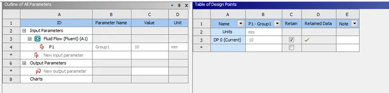
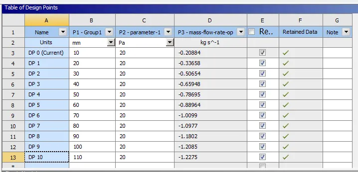
create an group of this component in parametric study for changing the height without changing an boundary condition of th given input creating a data point each position of the valve with same boundary condition with that computational time has reduces
creating the volumetric mesh on the domain with prepare tool ---> volume extude
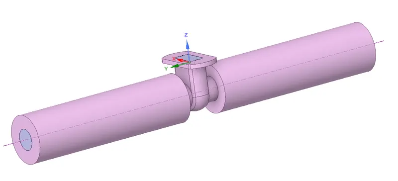
suppres all the outer wall and keep the volume domain and and go to the mesh deck
MESH
traget length 50 mm

Name selection for the boundary codition .
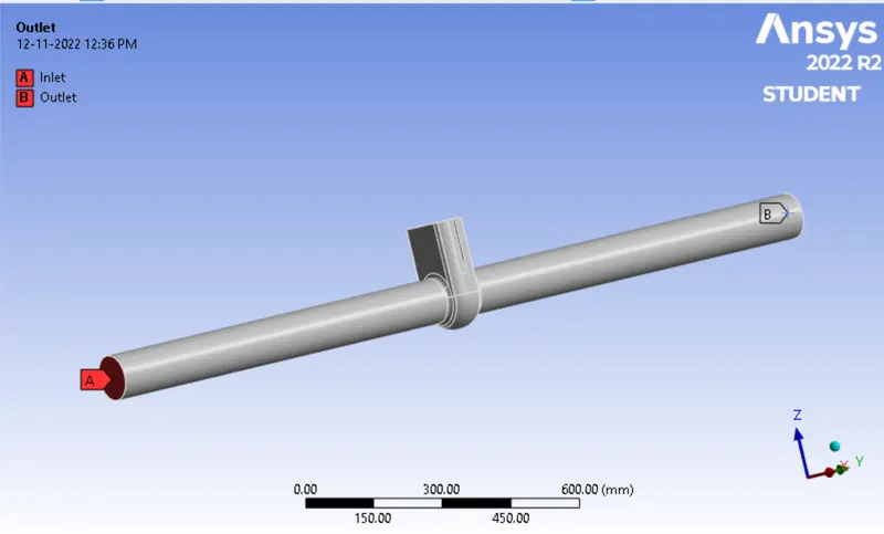
setup and solver settings
solver type
1) Absolute velocity formulation is preferred in applications where the flow in most of the domain is not rotating (e.g., a fan in a large room).
2) pressure based solver is used for incompressible flow at low speed
3) Time - steady state
4) gravity -9.81 m/s in Z direction
5) viscous models
k -epsilon ---> RNG---> swirl dominated fow
6) Marterials
set material to fluid
fluid ----> water Density = 998.2 kg/ m^3 , viscosity = 0.001003 kg/ ms
7)Cell Zone condition
Domain ----> fluid
8)Boundary condation
pressure inlet
The pressure inlet boundary condition defines an inflow condition based on the known pressure value (P) at the boundary. It is used when no flow rate is known
inlet --- pressure inlet @ 20 pa
outlet --- pressure outet
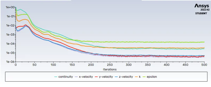
initialization @ run the simulation for 500 iteration
1) Gate Opening for 10%
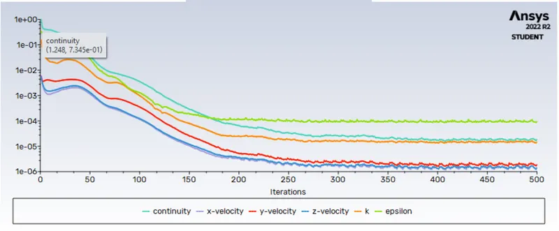
residual plot
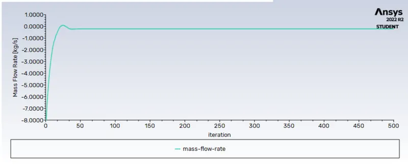
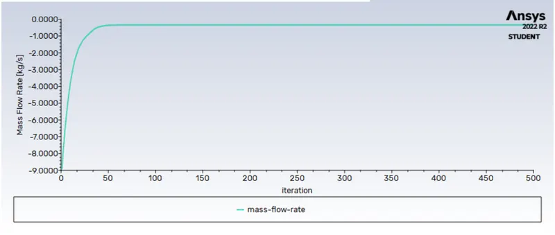
mass flow rate on outlet
pressure contour
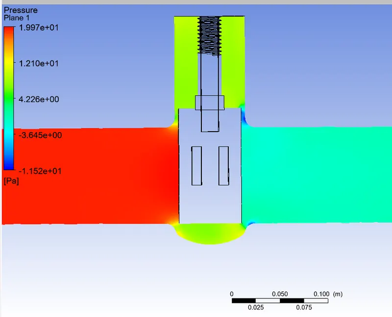
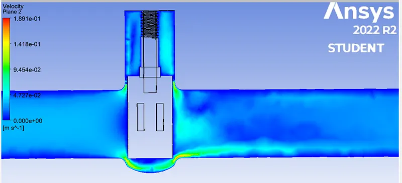
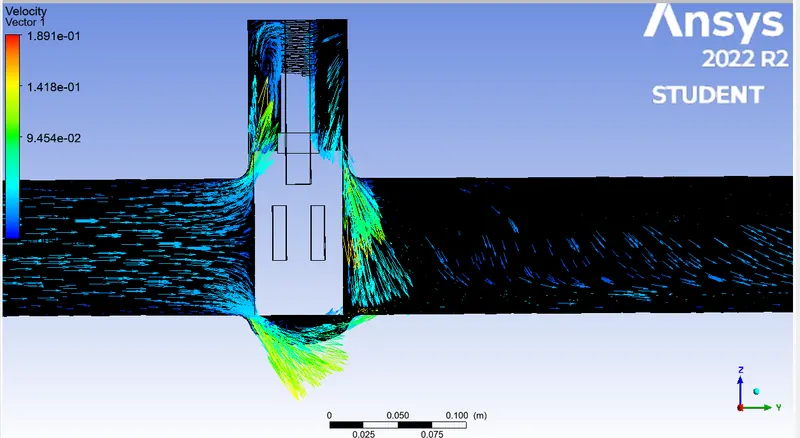
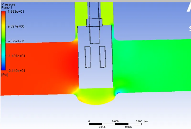
in inlet an high pressure as been devloped on the outlet gate edge the pressue drop is created and create velocity devlopment
velocity contour
velocity vector
1) mass flow rate on the outlet = -0.20884
cv = Q√ (SG - ΔP)
Q = -0.20884 kg/s = 3.31 gal/min kg/s ---> gal/min
SG = 1000/998.2≈1
ΔP = 0.0014241308
Cv=3.31√(1/0.0014241308)
CV Value: 62.046
Kv=0.865⋅Cv -------> 0.865 . 62.046 = 53.66979
parametric study
Gate open 20%
residual plot
mass flow rate
pressure contour
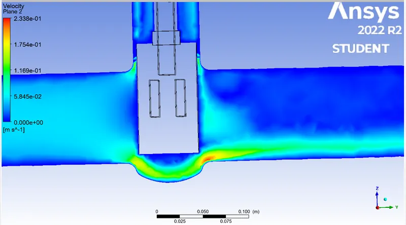
velocity contour
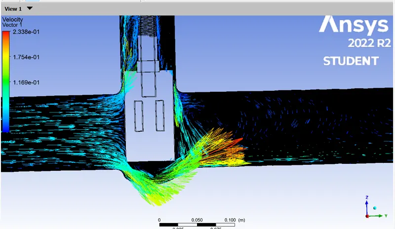
velocity vector
1) mass flow rate on the outlet = -0.33658
cv = Q√ (SG - ΔP)
Q = -0.33658 kg/s = 5.33 gal/min kg/s ---> gal/min
SG = 1000/998.2≈1
ΔP = 0.0014241308
Cv=3.31√(1/0.0027613319919657)
CV Value: 101.43
Kv=0.865⋅Cv -------> 0.865 . 101.43 = 87.739545
30mm
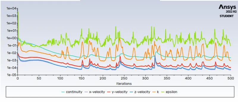
residual plot
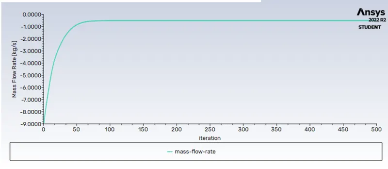
mass flow rate
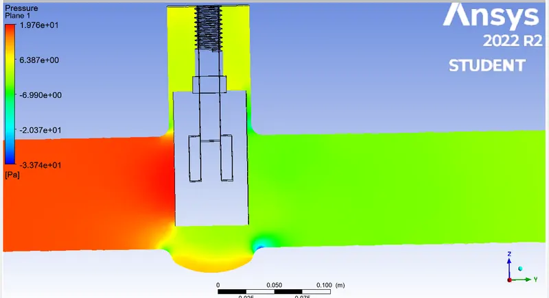
pressure contour
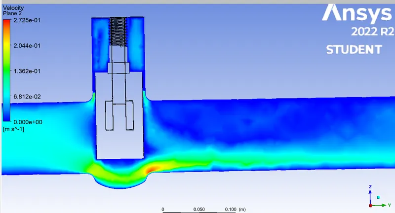
velocity contour
velocity vector
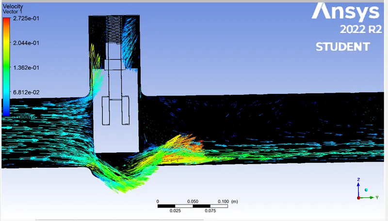
1) mass flow rate on the outlet = -0.50653838
cv = Q√ (SG - ΔP)
Q = -0.50653838 kg/s = 8.03 gal/min kg/s ---> gal/min
SG = 1000/998.2≈1
ΔP =0.00258326018496
Cv= 8.03√(1/0.00258326018496)
CV Value: 157.991
Kv=0.865⋅Cv -------> 0.865 . 157.991 = 136.66
40 mm
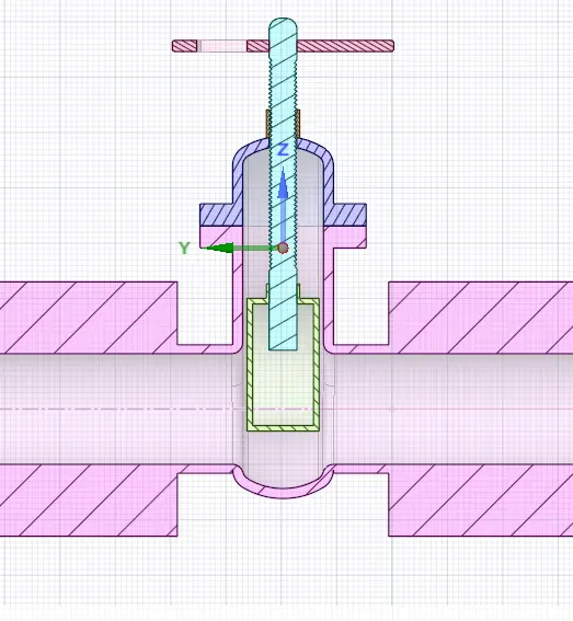
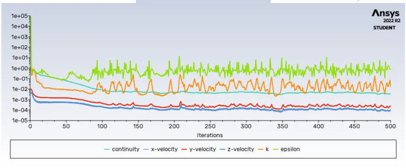
residual plot
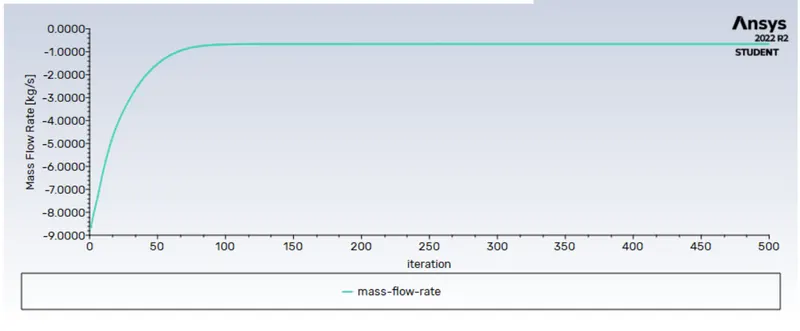
mass flow rate
pressure contour
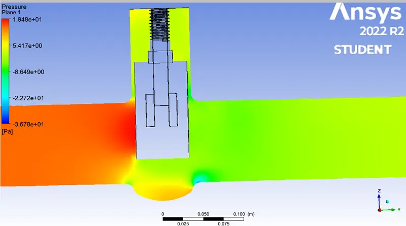
velocity contour
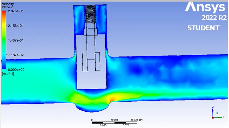
velocity vector
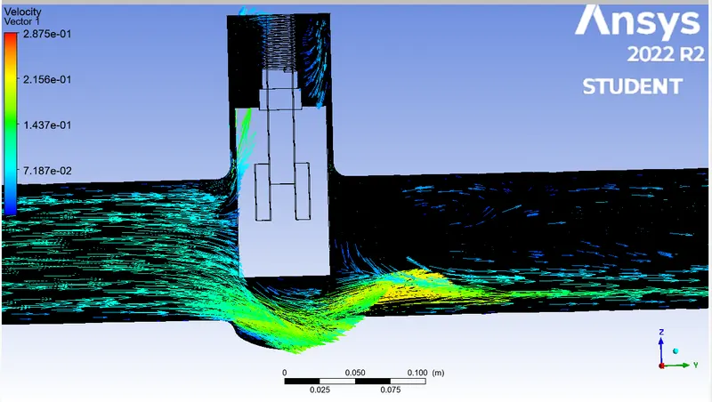
1) mass flow rate on the outlet = -0.65948234
cv = Q√ (SG - ΔP)
Q = -0.65948234 kg/s = 10.45 gal/min kg/s ---> gal/min
SG = 1000/998.2≈1
ΔP = 0.002360083076
Cv=3.31√(1/0.002360083076)
CV Value: 215.107
Kv=0.865⋅Cv -------> 0.865 . 215.107 = 184.23
50mm
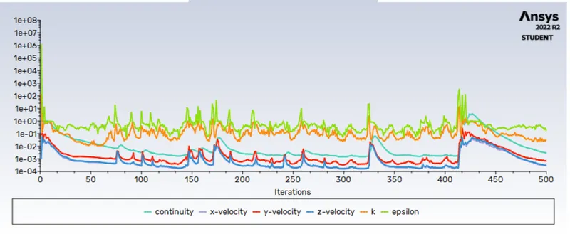
residual plot
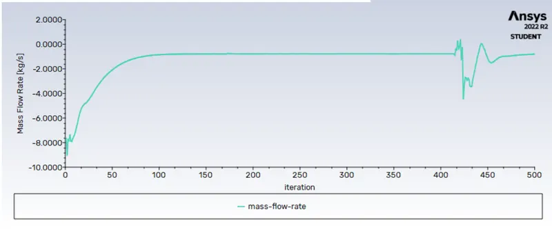
mass flow rate
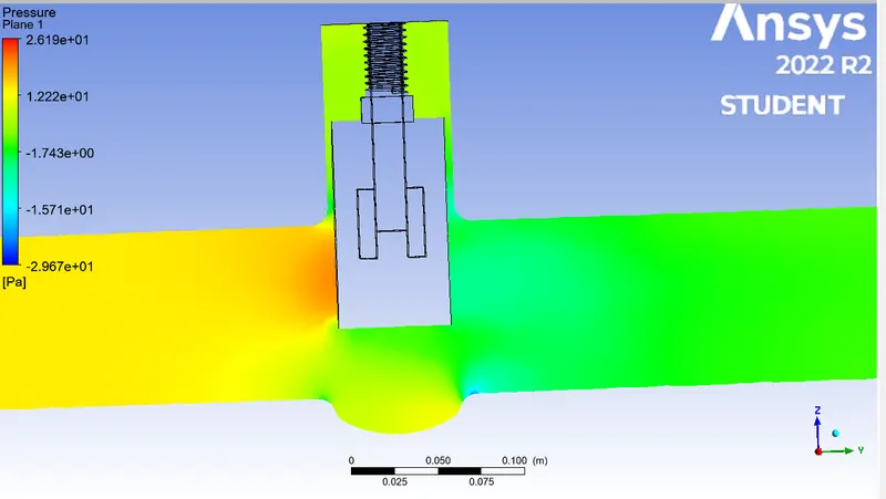
pressure contour
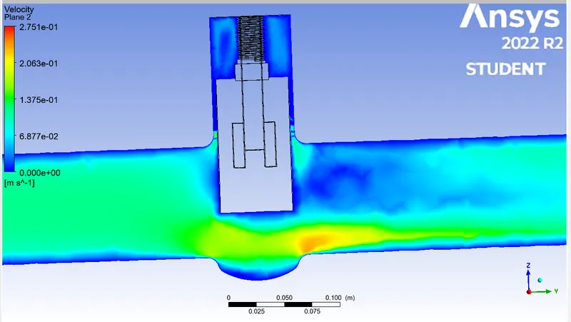
velocity contour
velocity vector
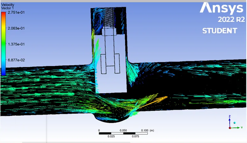
1) mass flow rate on the outlet = -0.7869511
cv = Q√ (SG - ΔP)
Q = -0.7869511 kg/s = 12.47 gal/min kg/s ---> gal/min
SG = 1000/998.2≈1
ΔP = 0.00213016925
Cv=3.31√(1/0.00213016925)
CV Value: 270.193
Kv=0.865⋅Cv -------> 0.865 . 270.193 = 233.71
60 mm
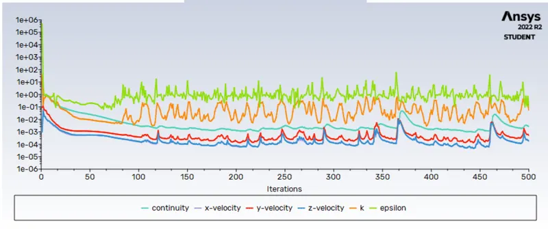
residual plot
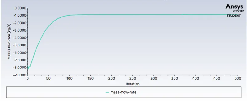
mass flow rate
pressure contour
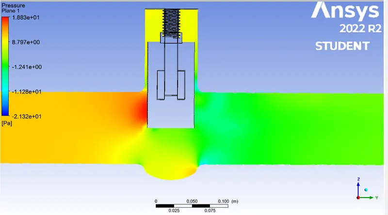
velocity contour
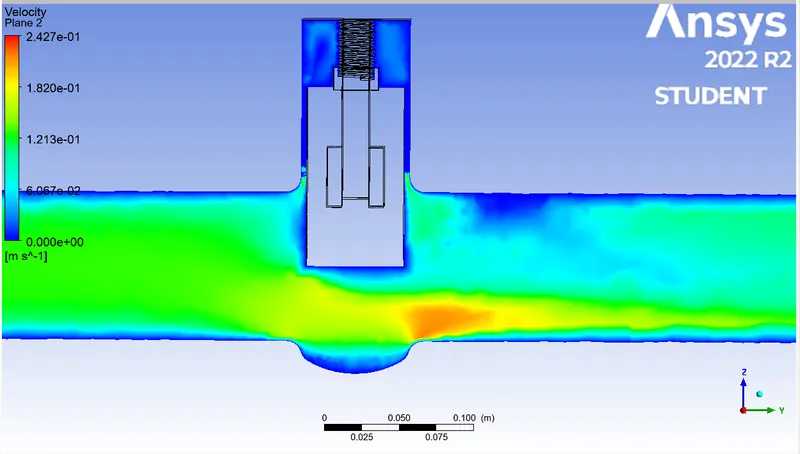
velocity vector
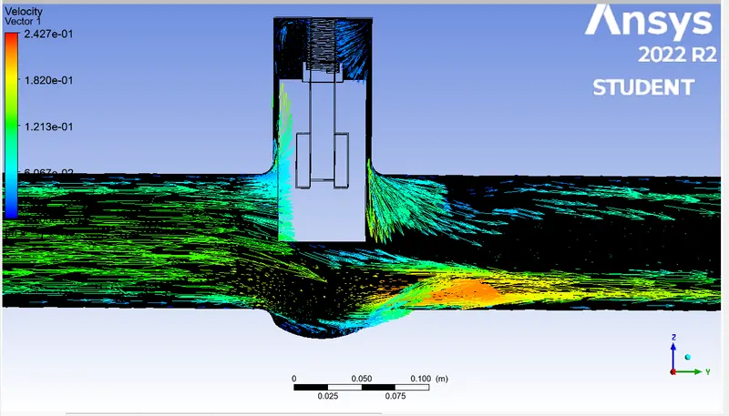
1) mass flow rate on the outlet = -0.88964287
cv = Q√ (SG - ΔP)
Q = -0.88964287 kg/s = 14.10 gal/min kg/s ---> gal/min
SG = 1000/998.2≈1
ΔP = 0.00192175
Cv=3.31√(1/0.00192175)
CV Value: 284.461
Kv=0.865⋅Cv -------> 0.865 . 284.461 = 246.05
70mm
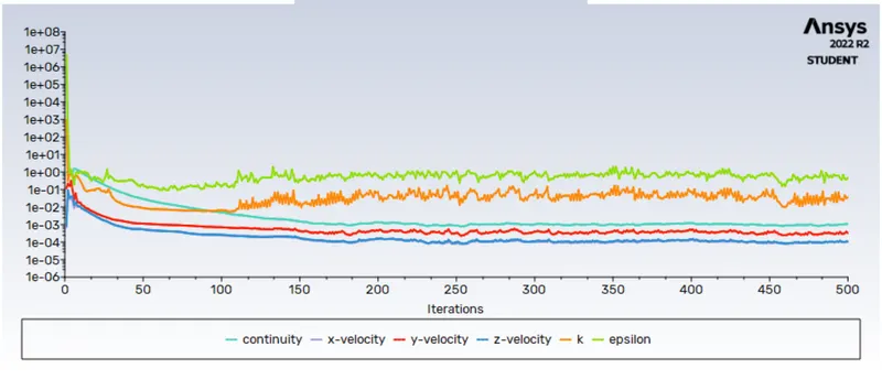
residual plot
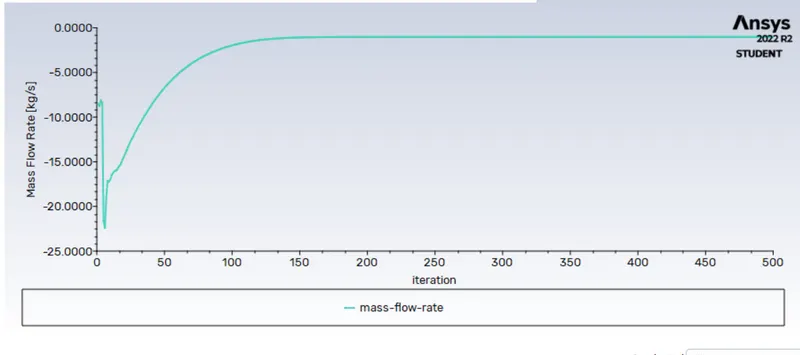
mass flow rate
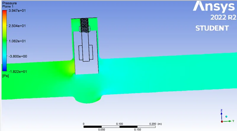
pressure contour
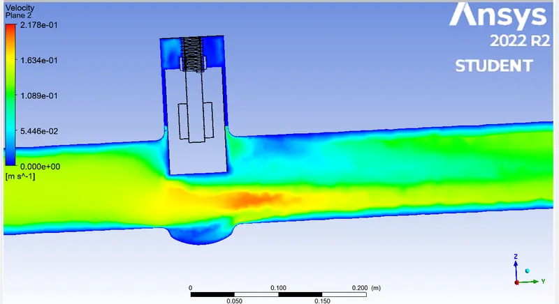
velcoty contour
velocity vector
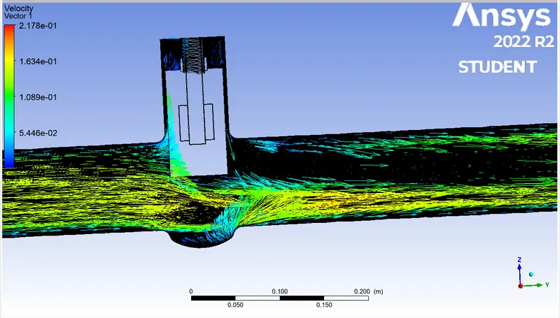
1) mass flow rate on the outlet = -1.0099038
cv = Q√ (SG - ΔP)
Q = -1.0099038 kg/s = 16.01 gal/min kg/s ---> gal/min
SG = 1000/998.2≈1
ΔP = 0.001642813448
Cv=3.31√(1/0.001642813448)
CV Value: 395.001
Kv=0.865⋅Cv -------> 0.865 . 395.001 = 341.67
80mm
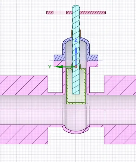
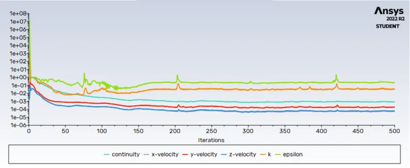
residual plot
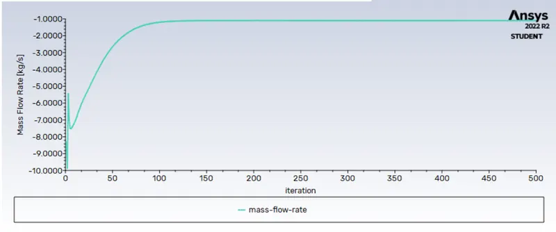
mass flow rate
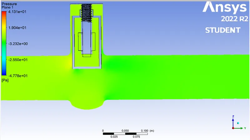
pressure contour
velocty contour
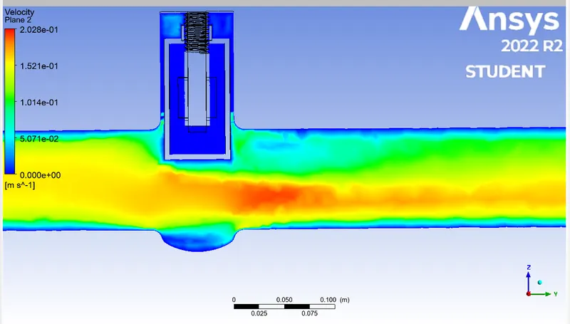
velocity contour
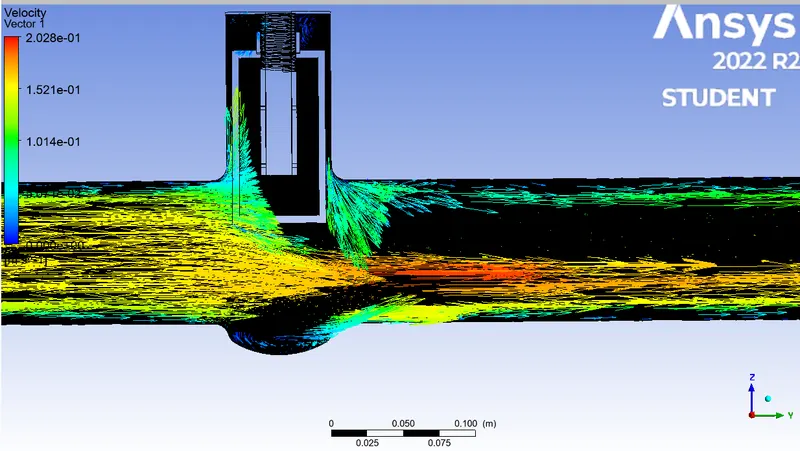
1) mass flow rate on the outlet = -1.0977116
cv = Q√ (SG - ΔP)
Q = -1.0977116 kg/s =17.40 gal/min kg/s ---> gal/min
SG = 1000/998.2≈1
ΔP = 0.0013974386
Cv=3.31√(1/0.0013974386)
CV Value: 465.45
Kv=0.865⋅Cv -------> 0.865 . 465.45 = 402.61
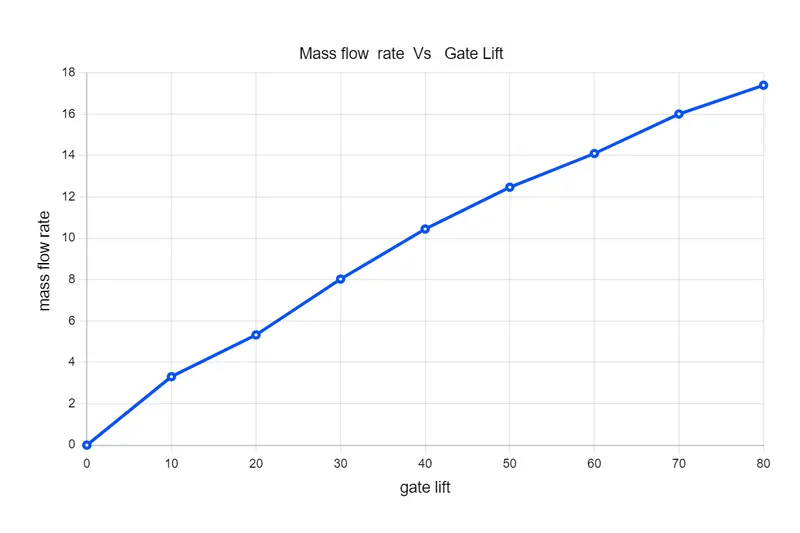
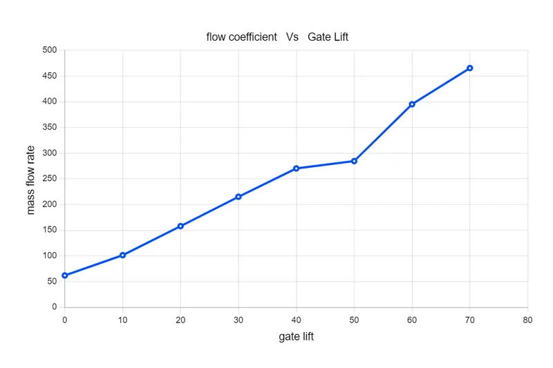
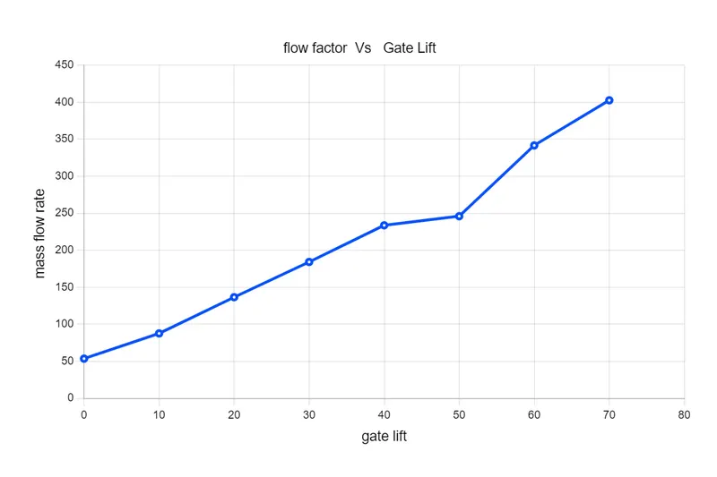
| case | mass flow rate {gal/min } | disk lifting | flow coefficient | flow factor |
| 1 | 3.31 | 10 | 62.046 | 53.66 |
| 2 | 5.33 | 20 | 101.43 | 87.73 |
| 3 | 8.03 | 30 | 157.991 | 136.66 |
| 4 | 10.45 | 40 | 215.10 | 184.23 |
| 5 | 12.47 | 50 | 270.193 | 233.74 |
| 6 | 14.10 | 60 | 284.46 | 246.05 |
| 7 | 16.01 | 70 | 395.001 | 341.67 |
| 8 | 17.40 | 80 | 465.45 | 402.61 |
mass flow rate VS gate lift
flow coefficient VS gate lift
flow factor Vs gate lift
conclusion
parametric study on the gate valve simulation by setting the opening from 10 % to 80%. is performed as the gate opens the pressue drop in the inlet and the vlocity keep increasing in outlet there is an incrementation in Mass flow rate, flow coefficient and flow factor.