Week 2 Challenge : Surface meshing on a Pressure valve
Surface meshing on a Pressure valve
- import the geometry from the file
- TOPO CLEANING
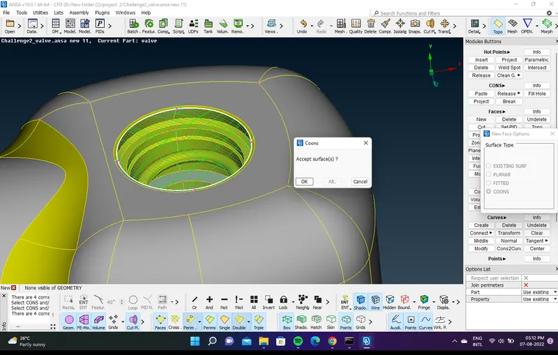
- fill the holes with fill holes option and the new face ----> coons
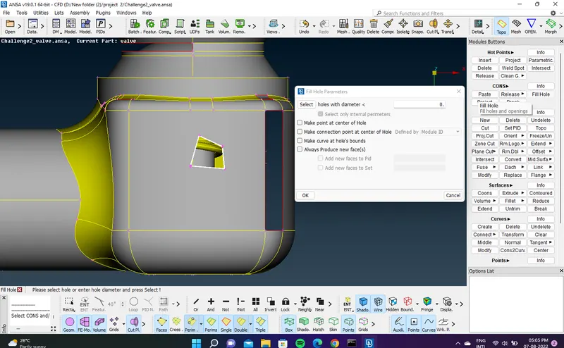
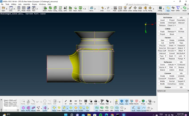
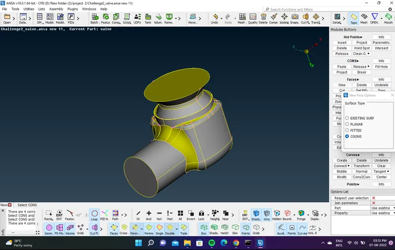
- close all opensurface for water tight geometry .
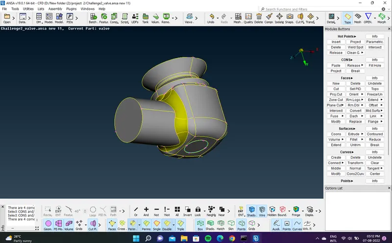
- PID: selection of all the entities of one selected PID
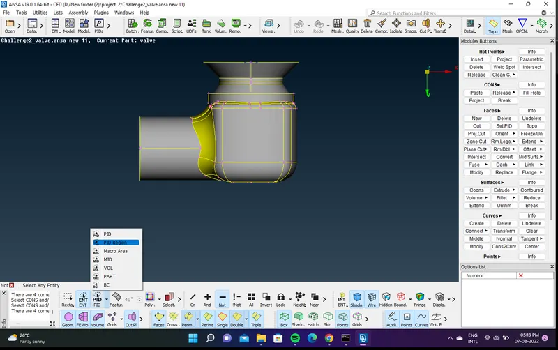
- PID region: selection of the entities of an unconnectedregion of one PID.
- select PID ----> PID REGION
- PID region is used in componets seperation when there is no conenction between the pid,s
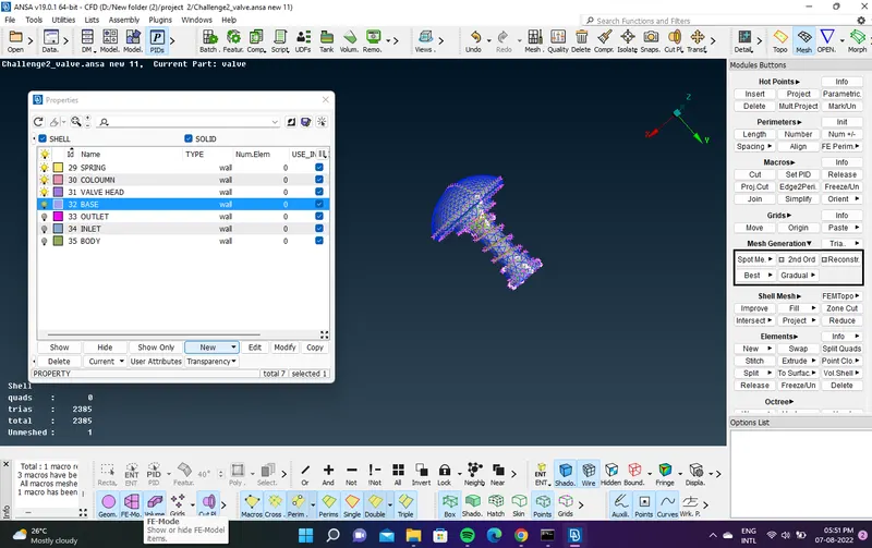
- convert the child components and boundary surface into pid,s as (inlet ,outlet , base surface , valve head ,column ,spring,body)
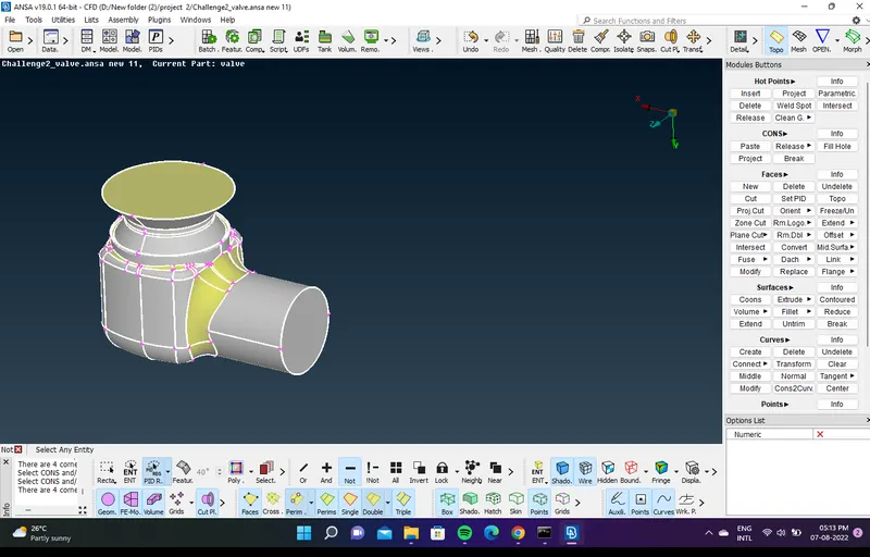
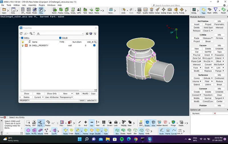
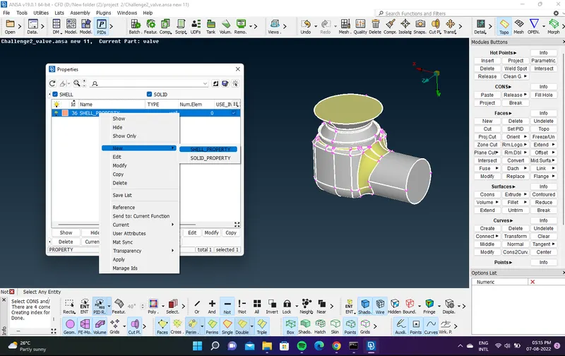
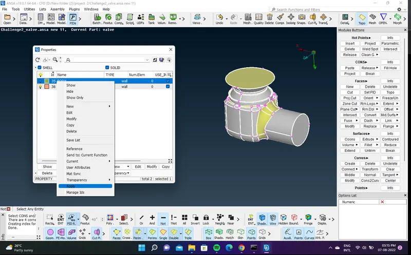
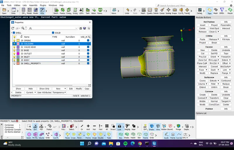
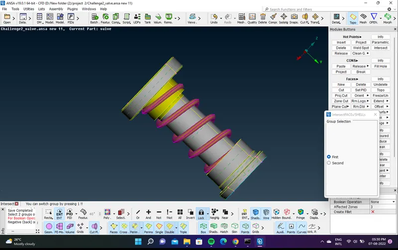
- penetration issue fixing
- spring is penetrain with coloumn
- intersect them face -----> intersect 1 spring 2 column
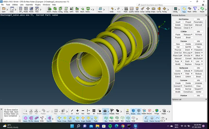
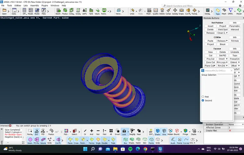
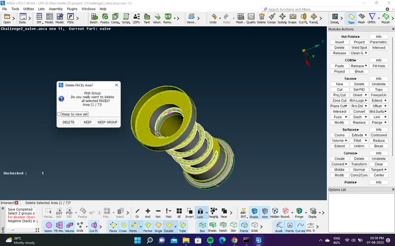
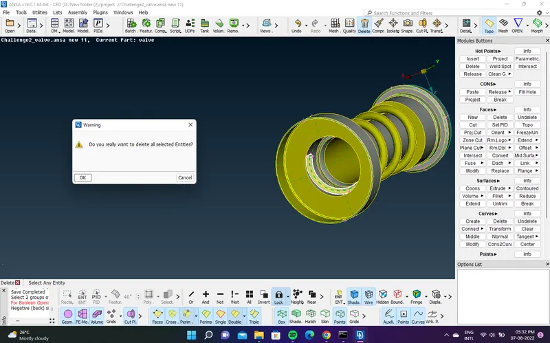
- identifi the unwanted surface in between of the components and delete it
- MESHING PART
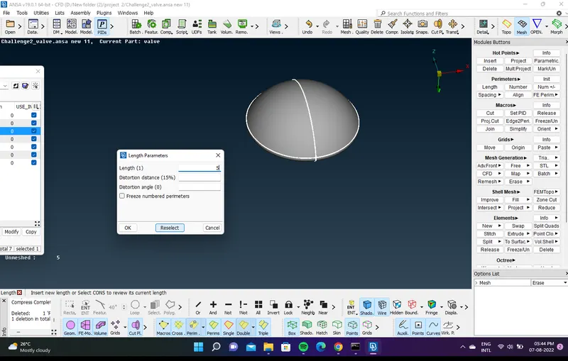
- MESH ------> PERIMETERS---> LENGTH 1)Perimeter ,macros
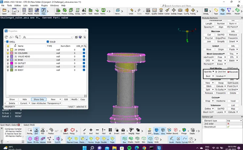
- MESH GENERATION ------> spot mesh
- Target length = 1mm, 3 mm and 5 mm (i.e. 3 cases)
- Element type = Tria
- MODEL 1
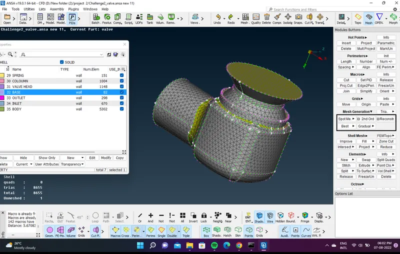
- Target length = 5 mm for whole geometry
- meshed pid wise and freeze it for to avoid mesh error in between the joints
- MODEL -2
- Target length = 3mm for whole geometry
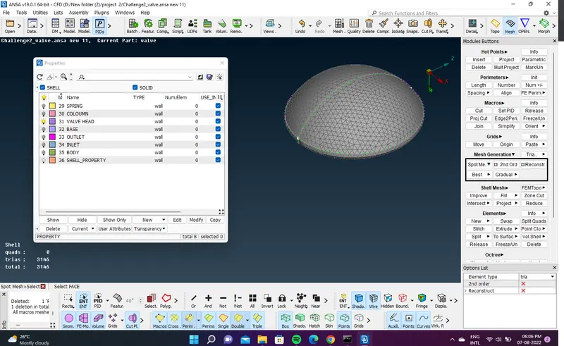
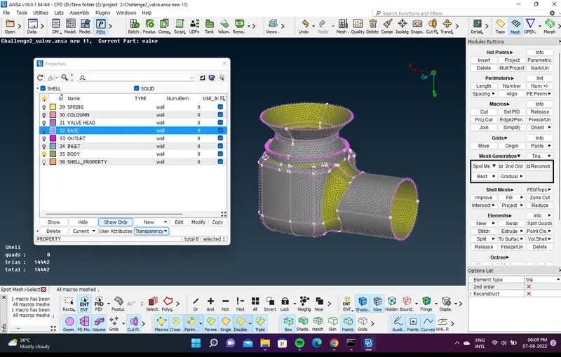
- measure the length between the node points
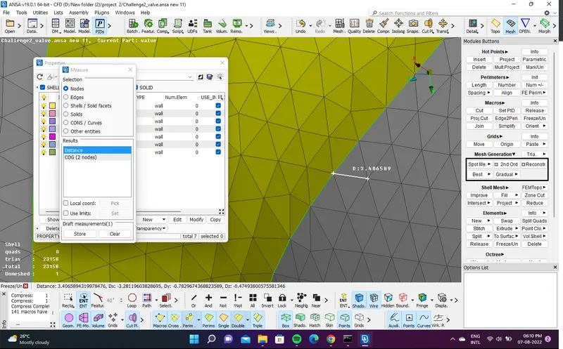
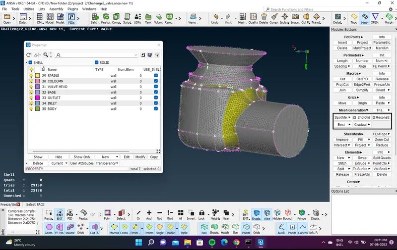
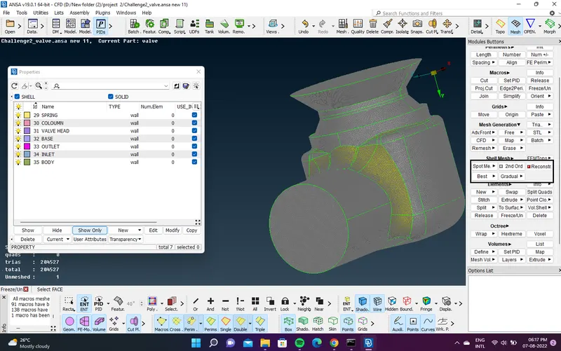
- MODEL -3
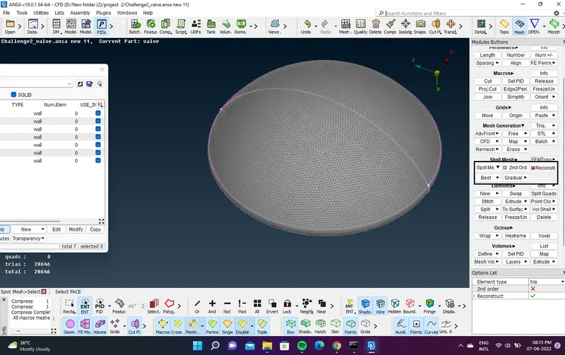
- Target length = 1mm for whole geometry
Report
- MODEL -3
- Target length = 1mm for whole geometry gives the good quality of mesh
- it occupid the whole surface of the geometry and give more number of elements in geomerty