Week 9 - Parametric study on Gate valve.
Aim :- Parametric study on Gate valve by setting the opening from 10% to 80%
Objective :-
- Perform parametric study by setting the opening from 10% to 80%
- Obtain the mass flow rate at the outlet for each design point
- Calculate the flow efficiency and flow factor
- Plot the graph for each opening
Theory of the project
Introduction
Gate valve : A gate valve is the most common valve for water supply systems. It represents a linear-motion isolation valve and has a function to stop or allow the flow. Gate valves got their name from the closure element sliding into the flow stream to provide shutoff and, therefore, acting like a gate.
Purpose of gate valve : Gate valves are used to isolate specific areas of the water supply network during maintenance, repair works, new installations, as well as to reroute water flow throughout the pipeline.
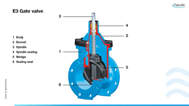
A resilient seated gate valve with a non-rising spindle consists of the following parts:
- wedge
- ductile iron valve body
- seating area
- stem (spindle)
- spindle bearing
- bonnet
- packing
Types of gate valves
Based on construction, gate valves for water supply systems can generally be divided into the following types:
- By wedge: parallel gate valves and wedge gate valves
- By seat: resilient seated gate valves
- By stem: with rising or non-rising stem.
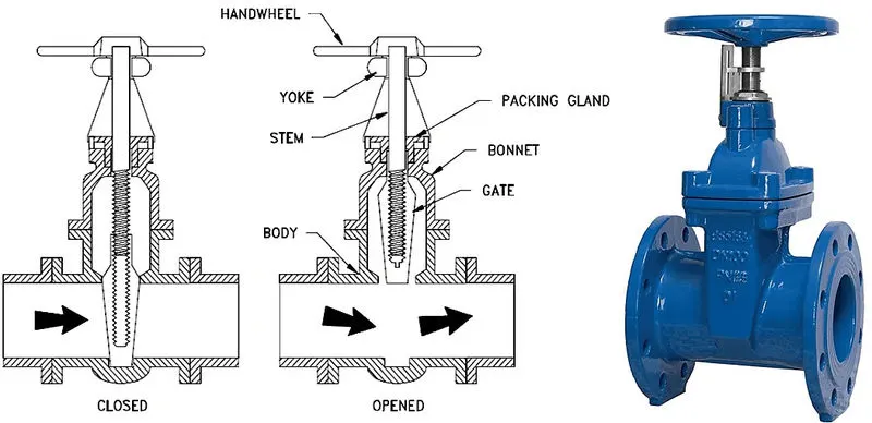
When the gate valve is fully open, the disk of a gate valve is completely removed from the flow. Therefore virtually no resistance to flow. Due to this, very little pressure drops when fluid passes through a gate valve.
PARAMETRIC STUDY :
Modelling and solving approach
1. Start the anys fluent workbanch
2. First import the geometry in spaceclaim
3. Pull the two sides of the gate disc and create the parameters
4. Extract the fluid volume by enble the necessary part of the geometry and supress the solid volumes
4. Meshing - baseline and refinement and named selection (Inlet and outlet)
5. Energy off (As we are not dealing with temp)
6. Steady state simulation using viscous K epsilon (RNG) model
8. Creating material (Water)
9. Boundary condition (pressure inlet , 10 Pa)
10. Hybrid initializing
11. Run Fluent solver
12. Post-processign and animation plots
Pre-processing
Importing the given geometry in spaceclaim. This is our given geometry.
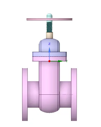
Now using pull tool in sketch pull the pipe's outer solid surfaces
Using move command we have lifted the valve of the gate and set lift of the valve as parameter in group in spaceclaim itself
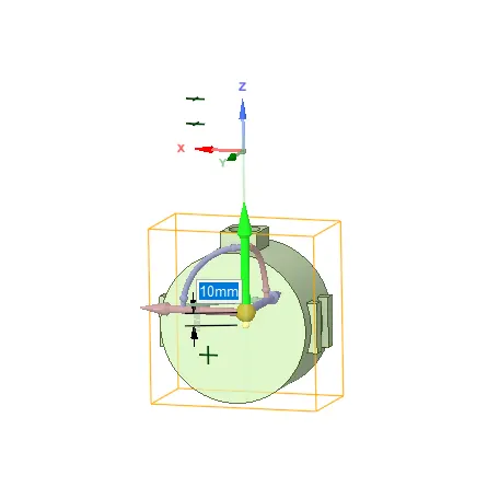
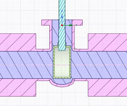
You can see the cut-section view of the gate disc in sketch mode before creating the fluid volume .
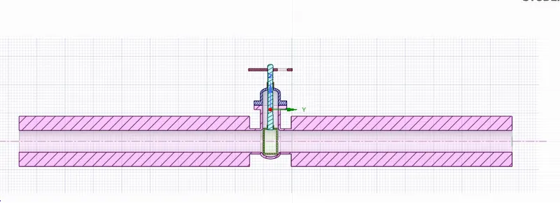
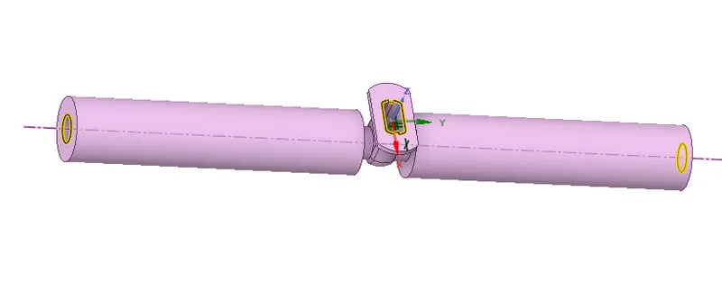
Next fluid volume has extracted by enable the bottom , disc and spindle and we have suppressed the unwanted component as suppress for physic.
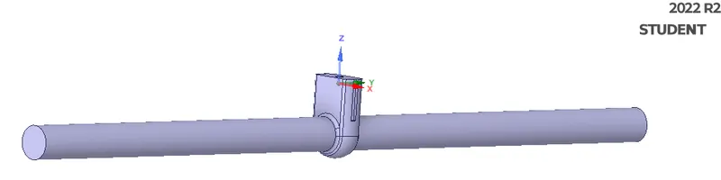
This is our fluid volume and we will go ahead with this fluid volume only.
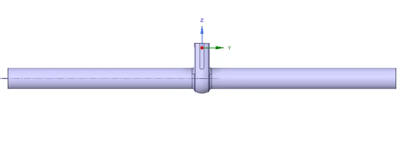
Meshing
- Open the meshing console.
- Click on the mesh and select generate mesh option.
- Now a basic mesh pattern will be created.
- Now we will run a baseline mesh having default size . We go to mesh size and put the desired value>> click on generate mesh tab.
- Now on the next step we will refine the mesh size br decreasing the element size to get the more accurate result .
For each case we have used same mesh size .
Aspect Ratio : We know that ratio between largest and smallest edge of an element is known as Aspect ratio.
Aspect ratio = 1 is ideal
In general Aspect ratio are maintained between 1 to 5 .
In our case it is lying between 1 to 2.5 .

Skewness : Skewness is measured by quantifying the deviation from the ideal shaped. And acceptable range is 0 to 0.5.
In our case it is between 0 to 0.35 . That is very good for the mesh quality .

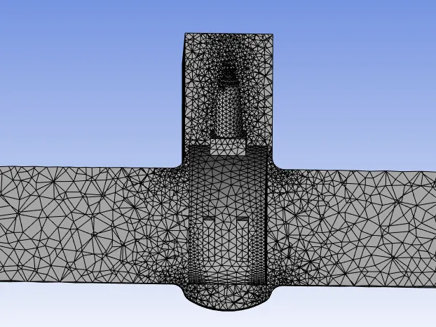
We have created the section plane in meshing in order the see the cutsection view.
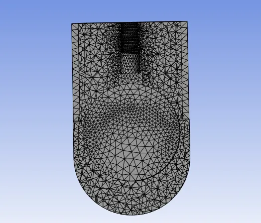
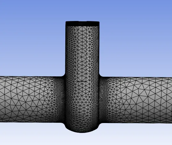
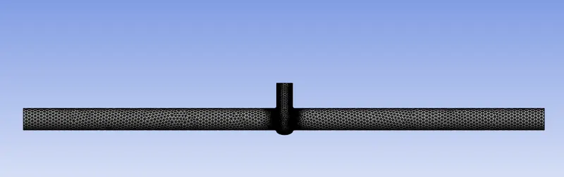
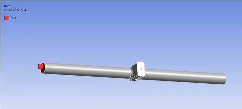
Named selection
Inlet
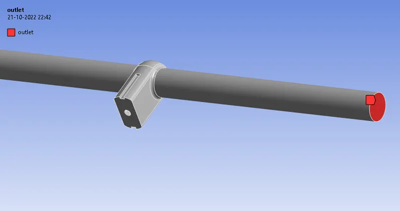
Outlet
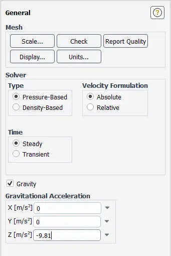
Setting up physics
Solver type - Pressure Based
Gravity (-9.81m/s^2 ) is enabled in negative z direction as gravity is acting in negative z direction in our problem.
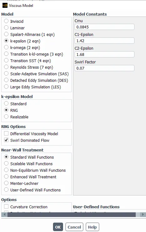
K -epsilon RNG model is used here as it will give more accurate result in our case .
Solver - Steady state
K -epsilon RNG model is used here as it will give more accurate result in our case .
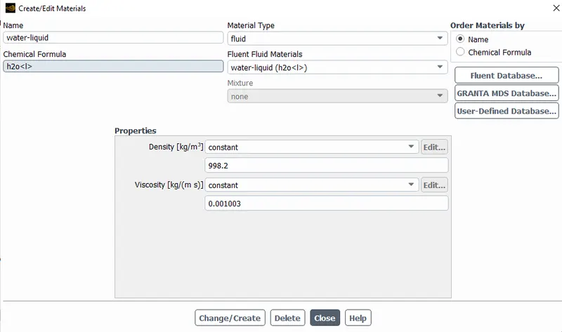
We have created the material from fluent database ( Water-liquid) and deleted the default material air .
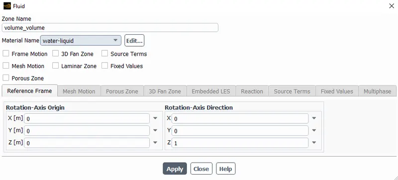
Water-liquid has used in cell zone condition .
To obtain the mass flow rate at the outlet and to Perform parametric study , surface report definition has been created by enabling the create output parameter.
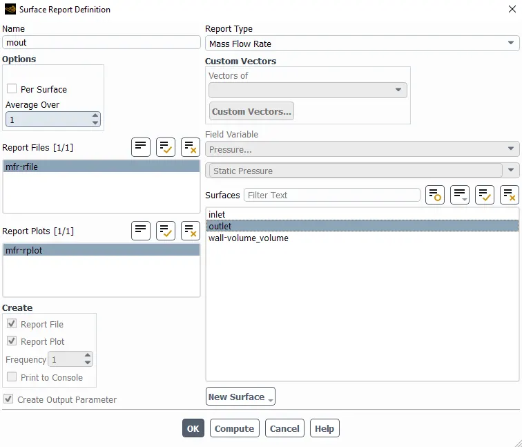
Prametric study
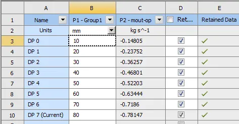
Results
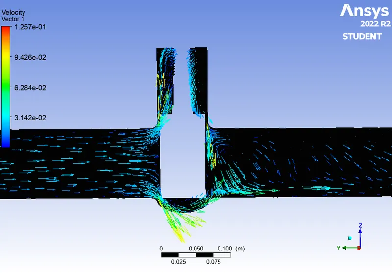
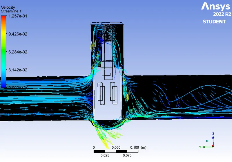
DP 0_ 10 mm
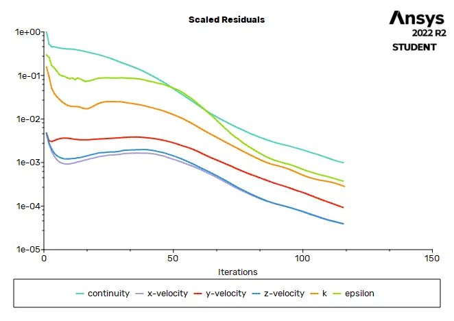
Residual plot
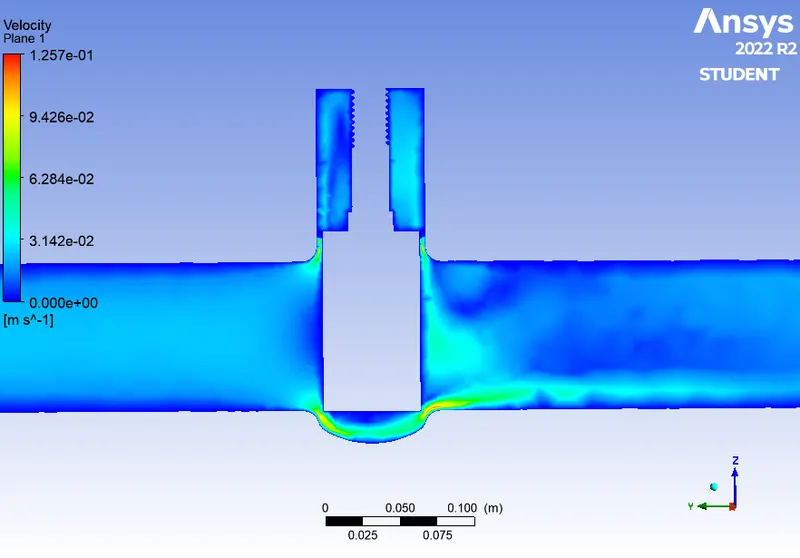
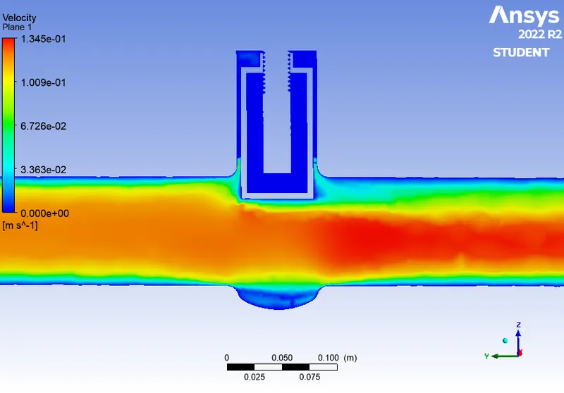
Velocity contour in yz plane
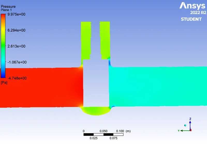
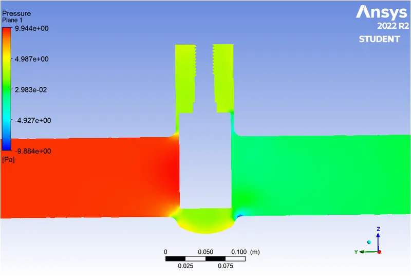
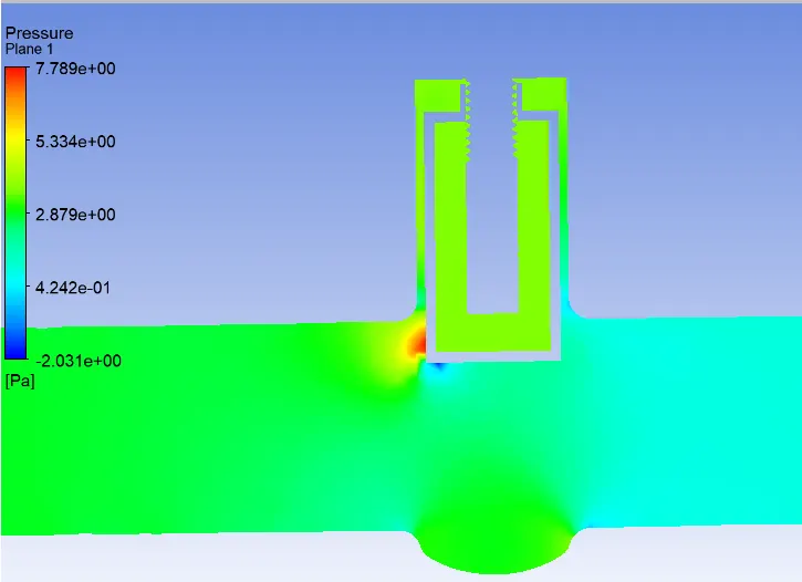
Pressure contour in yz plane
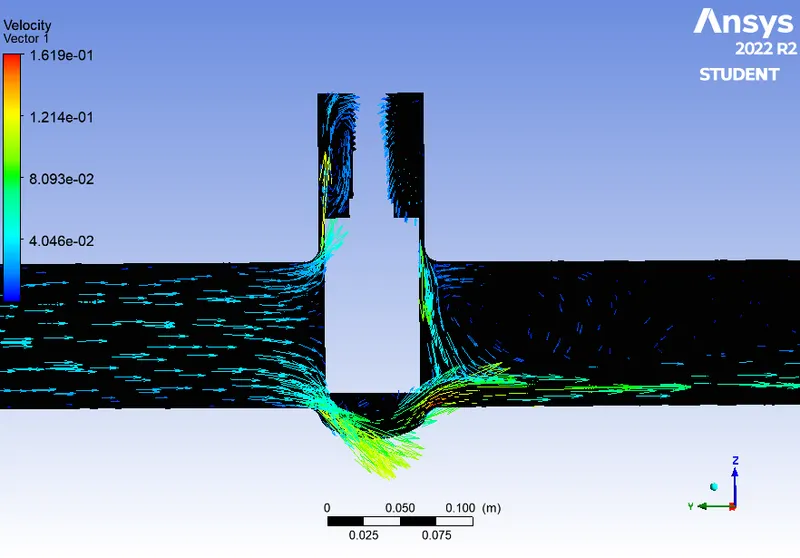
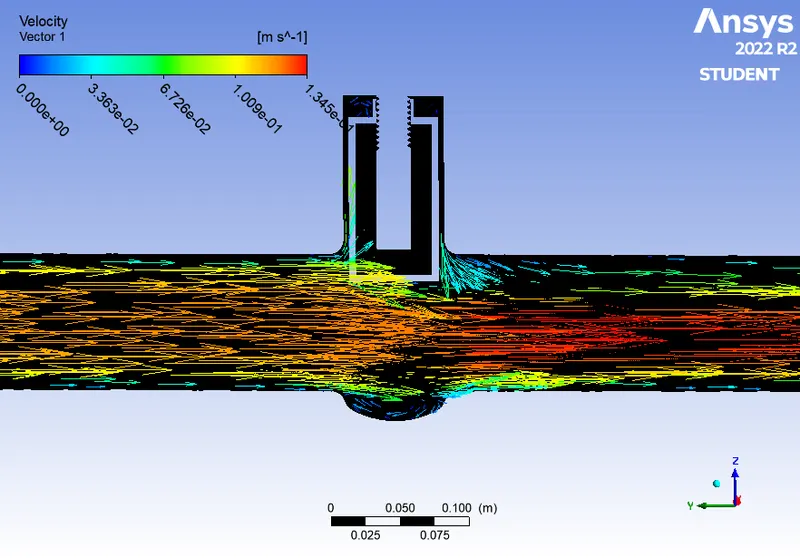
Velocity vector
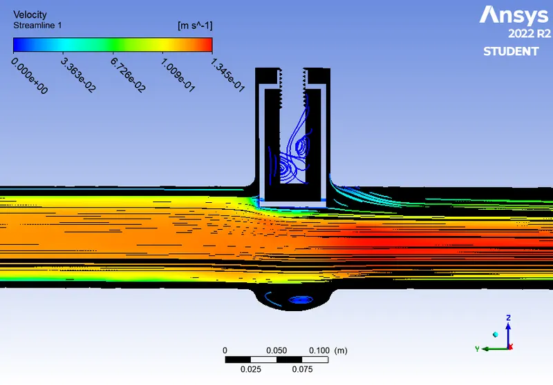
Streamline
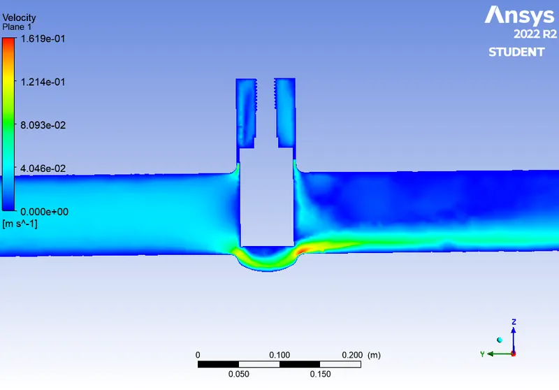
DP 1_ 20 mm
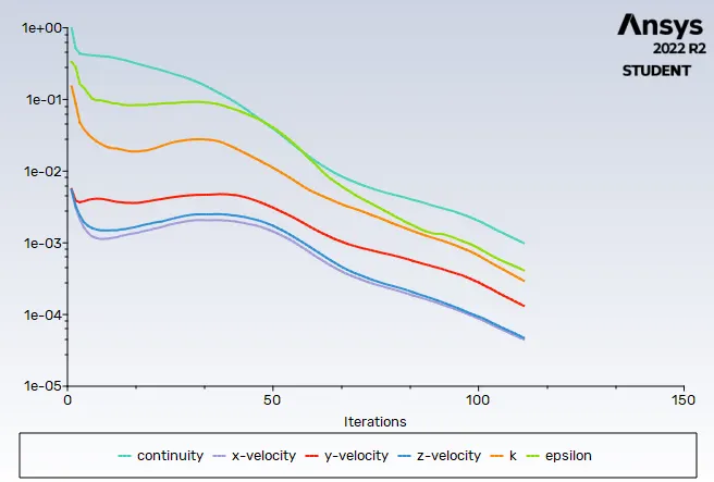
Residual plot for convergence
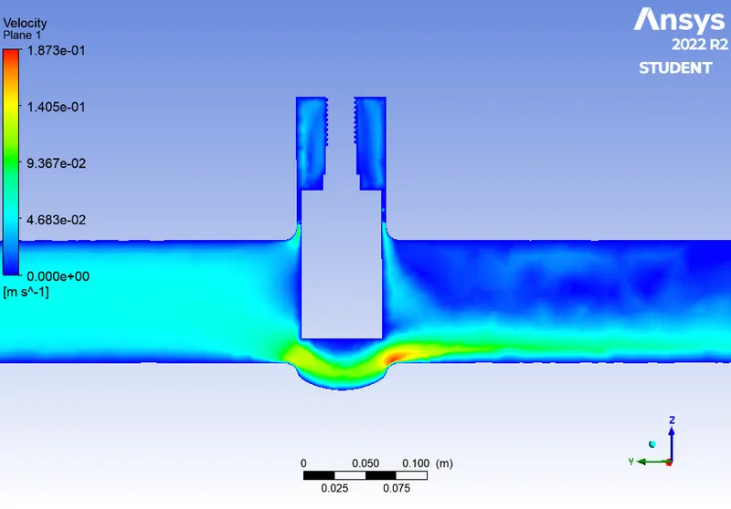
Velocity contour in yz plane
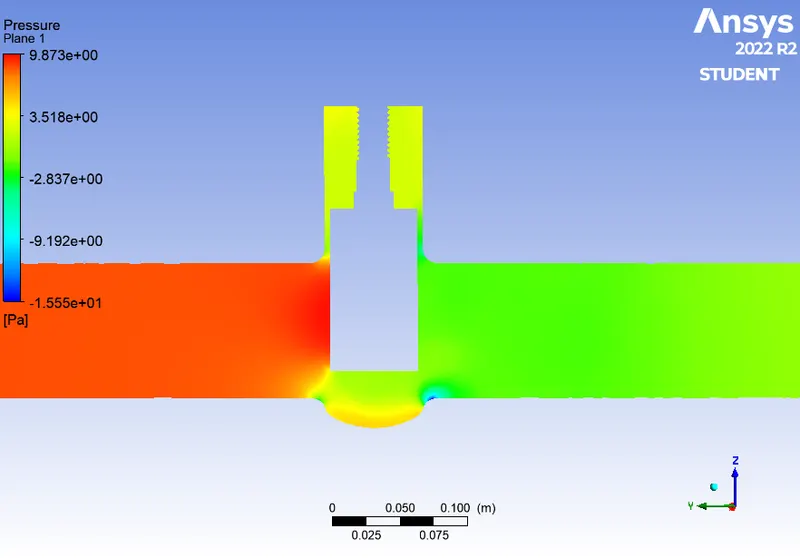
Pressure contour in yz plane
Velocity vector
DP 2_ 30 mm
Velocity contour in yz plane
Pressure contour in yz plane
Velocity vector
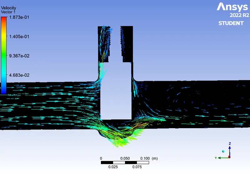
Streamline
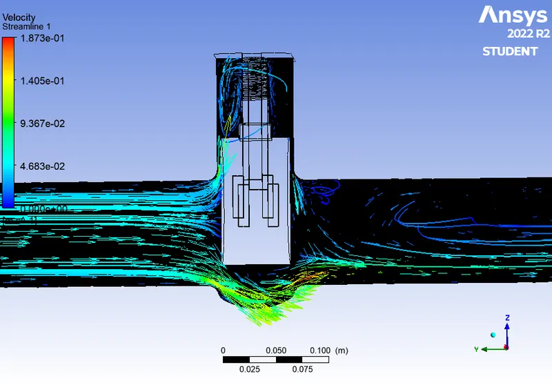
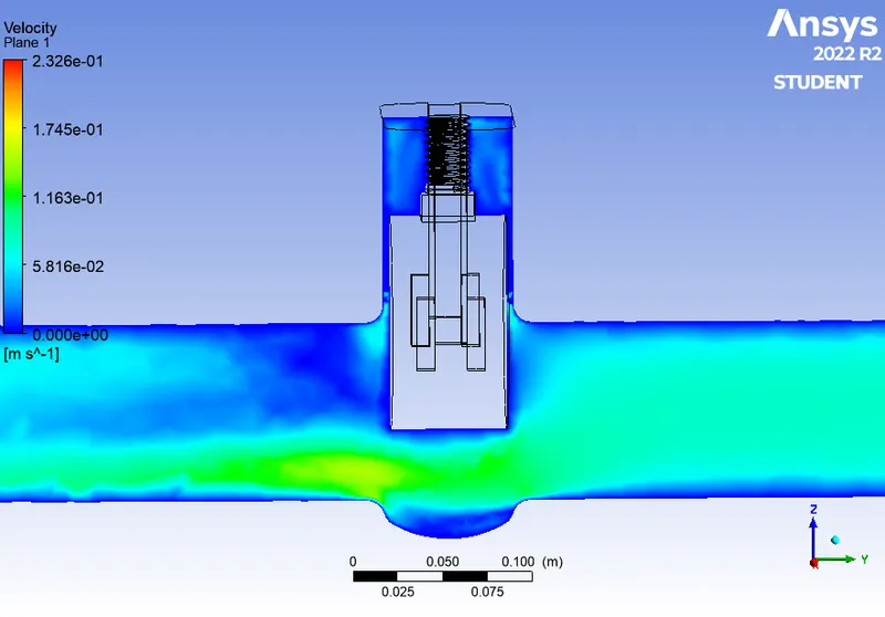
DP 3 40 mm
Velocity contour in yz plane
Velocity vector
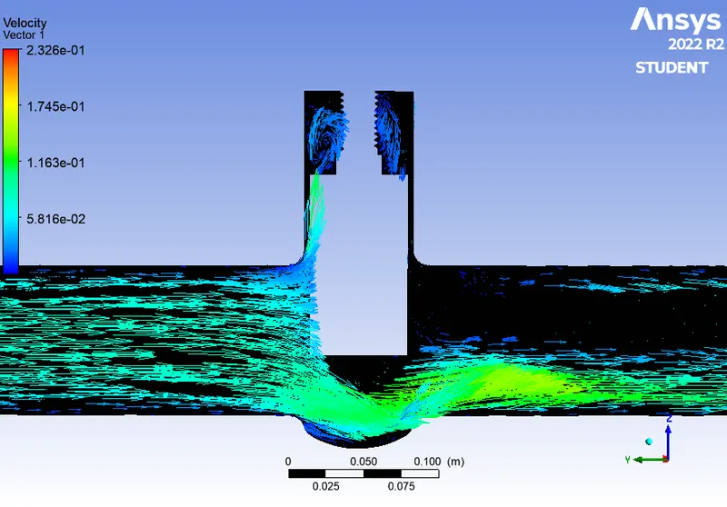
Streamline
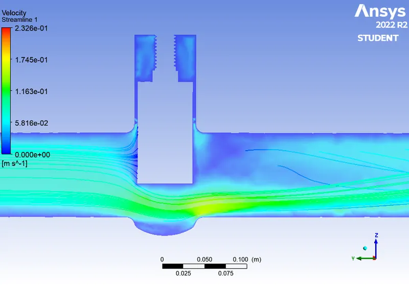
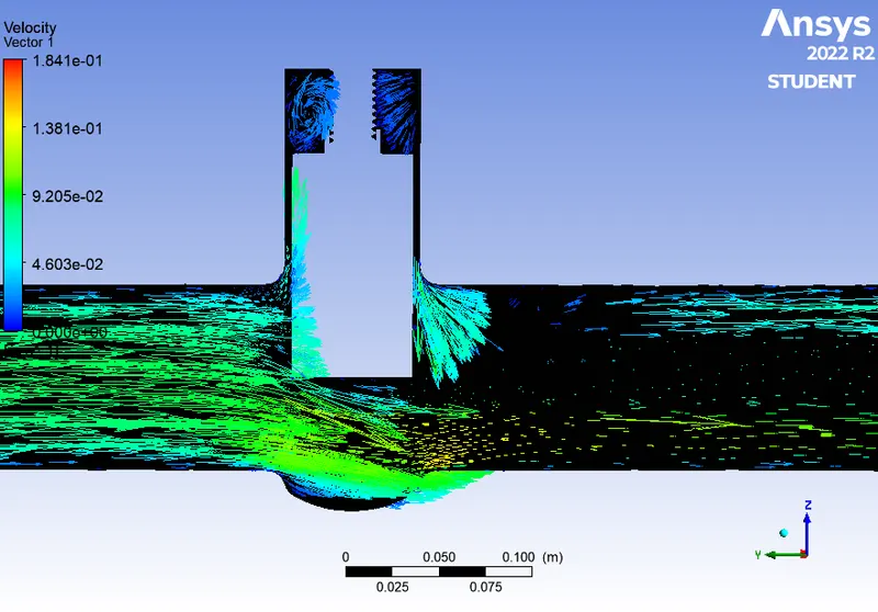
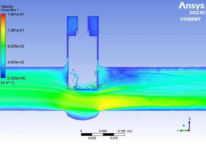
DP 4_ 50 mm
Velocity contour in yz plane
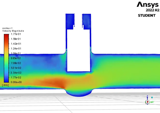
Pressure contour in yz plane
Velocity vector
Streamline
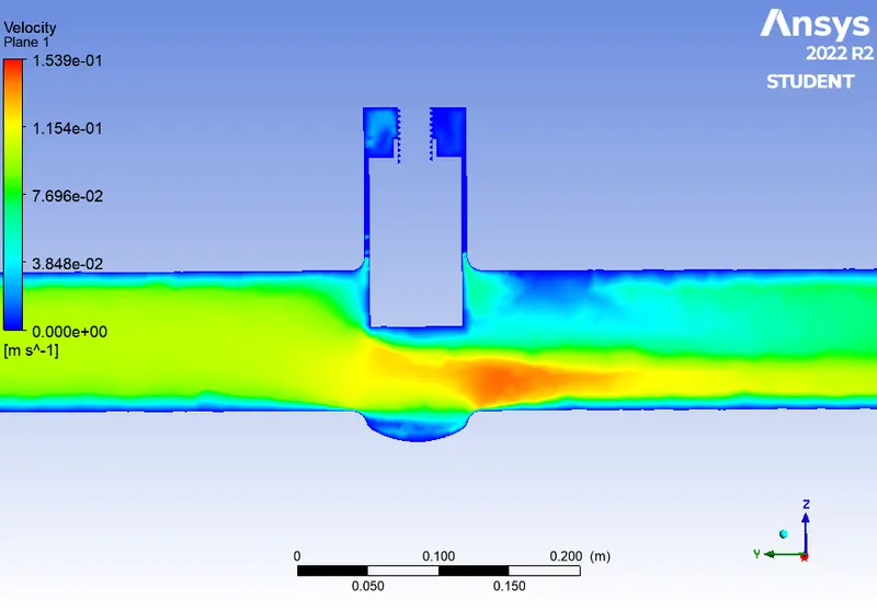
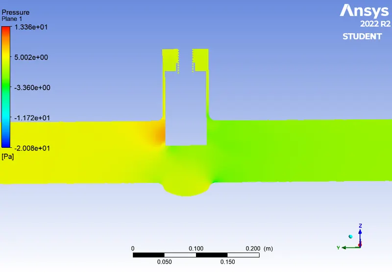
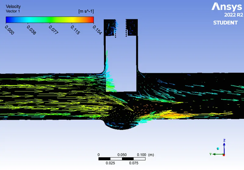
DP 5_ 60 mm
Velocity contour in yz plane
Pressure contour in yz plane
Velocity vector
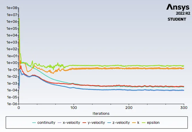
DP 6 70 mm
Residual for convergence
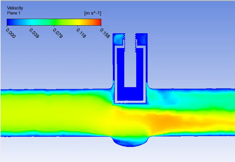
Velocity contour in yz plane
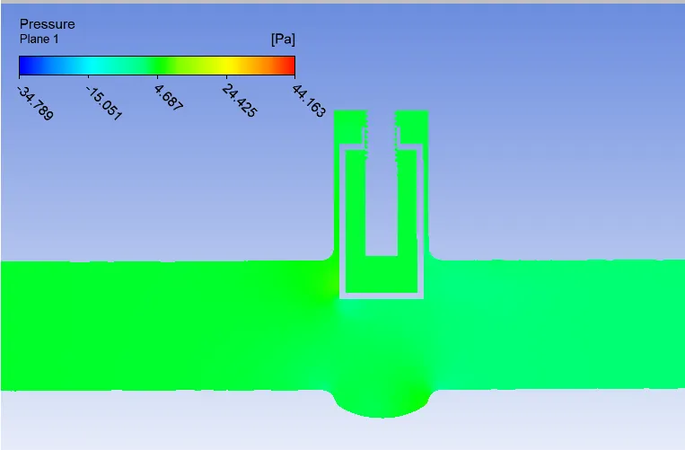
Pressure contour in yz plane
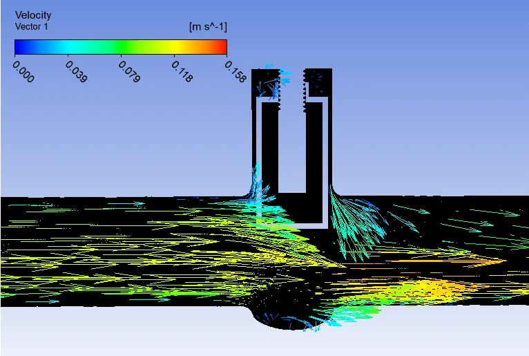
Velocity vector
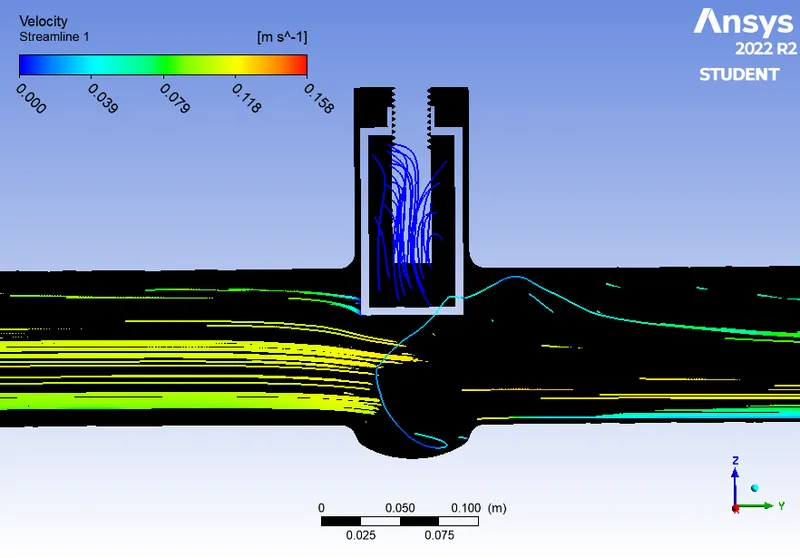
Streamline
DP 7_ 80 mm
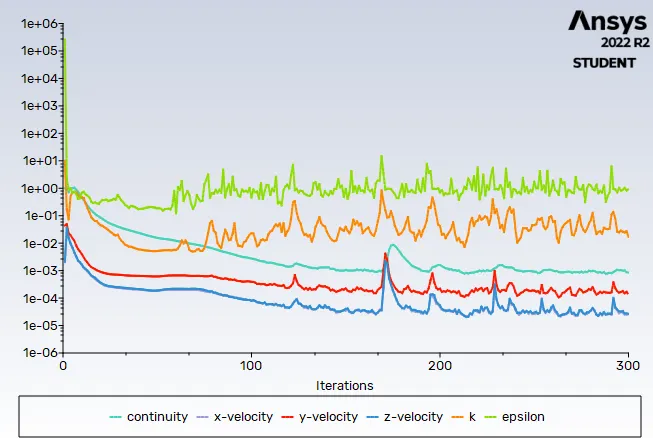
Residual plot
Velocity contour in yz plane
Pressure contour in yz plane
Velocity vector
Streamline
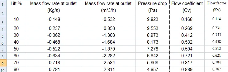
Calculation of mass flow rate : The mass flow rate is defined as the rate of movement of liquid pass through a unit area. The mass flow is directly dependent on the density, velocity of the liquid, and area of cross-section. Unit = kg/s
mass flow rate `m = rho* A*V`
where , `rho` = density of the water
`A` = cross sectional area
`V`= velocity of water
Flow coefficient : Valve Flow Coefficient (Cv) is a valve's capacity for a liquid or gas to flow through it. It describes the relationship between the pressure drop across an orifice valve or other assembly and the corresponding flow rate.

where , Cv = flow coefficient
Q = rate of flow
Sg = specific gravity of fluid(water)
`Delta P` = pressure drop across the valve
Flow factor : It indicates how much volume of a fluid flows through a valve at a given time. It is denoted by Kv. Unit = m^3/h
Relationship between Kv and Cv is :
Cv = 1.16 Kv
Kv = 0.862 Cv
For Gate disc lift = 10 mm
Specific gravity = 1000/998.2 = `approx`1
Pressure in inlet = 10 Pa
Pressure at outlet = 0
So, pressure difference `DeltaP`= 0
Cv = mass flow rate ( 0.532 ) * `sqrt (1/10)`,
= 0.532*0.316
= 0.168
Kv = 0.862*Cv = 0.114
We have calculated Flow factoe and flow coefficient from 10 to 80 mm lift of the gate disc by following the same procedure.
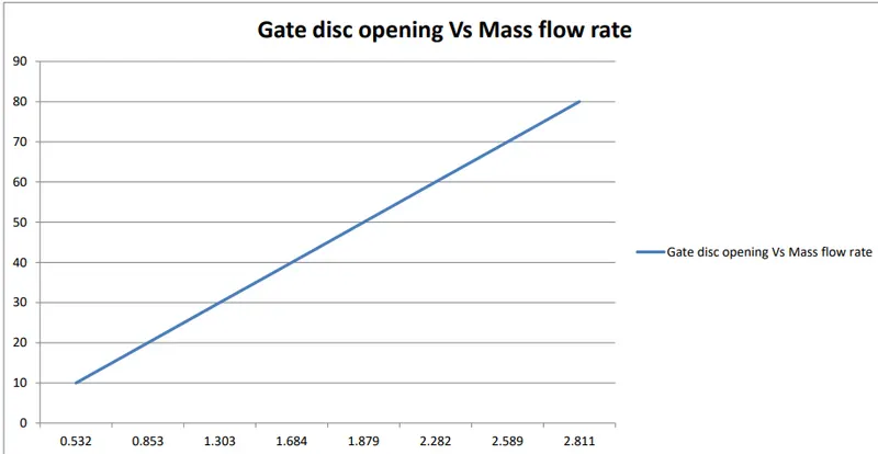
Gate disc opening Vs Mass flow rate graph
Along x axis - Mass flow rate
Along y axis - Lift
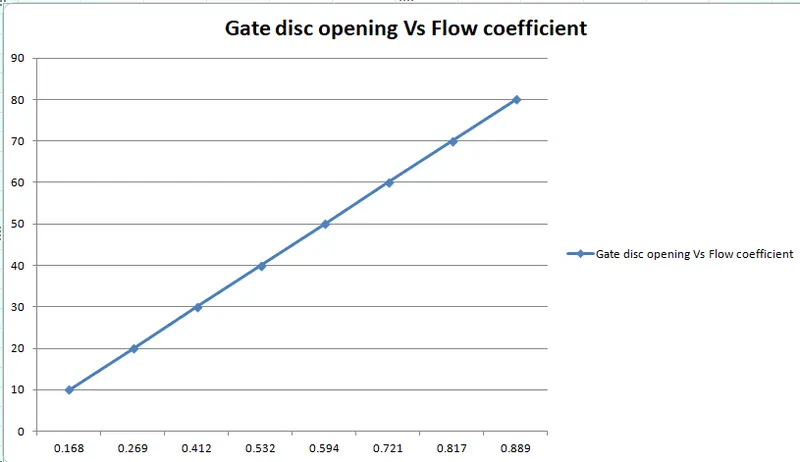
Gate disc opening Vs Flow coefficient graph
Along x axis -Flow coefficient
Along y axis - Lift
Mass flow rate , Flow coefficint , Flow fector Vs Lift
Along x axis - Lift
Along y axis - Mass flow rate , Flow coefficint , Flow fector
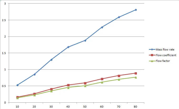
Observation :- From the above graphs we can say that
- With the increasing of the opening of the Gate Valve or Lift , Mass Flow Rate is increasing.
- With Increases in Mass Flow Rate, there is an increment in Flow Coefficient.
- Flow Factor is also increasing at each Design Point from 10 to 80 mm Lift.
- So, Graph of Mass Flow Rate, Flow Coefficient and Flow Factor go linearly with Gate Disc Opening.
Conclusion :-
1. Finally we have performed the parametric study on the gate valve simulation by setting the opening from 10 % to 80%. Also we have calculated the mass flow rate, pressure drop, flow coefficient and flw factor using the formula .
2. And to visualize the effect in Flow coefficient , mass floe rate with the increasing of the opening of the valve we have plotted the graph.
3. When the valve is fully opened for 80 % lift , mass flow rate, Cv, Kv becomes maximum as we can see in above graph.
References :-
https://skill-lync.com/knowledgebase/gate-valve-parametric-study-help
https://skill-lync.com/knowledgebase/parametrizing-in-ansys-fluent
https://en.wikipedia.org/wiki/Gate_valve
Thanks
Sk Tarif Ali