Project 1 : CFD Meshing for Tesla Cyber Truck
Title :- CFD Meshing for Tesla Cyber Truck
Aim / Objective :- For the given model, check and solve all geometrical errors on half portion and Assign appropriate PIDs. Perform meshing with the suitable Target length and element Quality criteria . Then mesh the wind tunnel only surface mesh not volume as it will take more than 2 days to perform.
Name of the PIDs and target length for the given model:
I have given four PIDs for tyres, as it was taking more time for surface meshing also for body part.
1.ty 1
2.ty 2
3.ty 3
4.ty 4
5.Body part 1
6.Body part 2
7.Body part 3
For tyres target length = 2 mm
For body parts target length = 3 mm
Topo cleanup - Set of tools for Geometry clean-up and for setting up of PIDs.
Surface mesh - A surface mesh or 2 D mesh consists of a set of polygonal faces, often triangles, that, taken together, form a surface covering of the object.
Volume mesh - In 3D computer graphics and modeling, volumetric meshes are a polygonal representation of the interior volume of an object.
In our case topo and surface mesh will be performed . AS volume mesh will take more than 2 days , volume mesh will not be performed here.
Tools to import the object -
1. Function Name : Open
Summary :
This function activates the File Manager and enables the input of data from a neutral format file or an ANSA database file. The neutral CAD formats currently supported are the VDA_FS, the IGES and the STEP format.
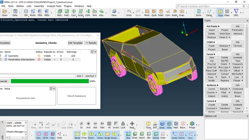
Then go to check manager to check the existing errors( Like - single coons, triple coons, unfinished surface , hollow, etc) in the given model.
Required tools for topo clean up :-
Required tools for topo cleanup -
1. Summary:
This function defines a new surface by selecting its boundary curves and creates a corresponding face that covers the new surface. The calculated surface appears as a net.
Function List :
New [COONS]
New [EXISTING SURF]
New [PLANAR]
New [FITTED]
2. Function Name : Cut
Summary :
This function cuts (splits) an existing Face or joins faces if inverse operation is applied (right mouse button).
3. Function Name : Project
Summary :
This function projects, as CONS or 3D Curves, a number of selected 3D-curves, CONS, element edges, line elements or Hexa Box edges on a number of selected Faces, WPLANEs and CROSS_SECTIONs, in a user controlled direction.
4. Function Name : Parametrical
Summary :
This function defines a new Node or Hot Point parametrically on a 3D-curve segment or a CONS segment.
5. Function Name : Topo
Summary :
This function automatically creates topological conditions between selected adjacent CONS.
6. Function Name : Fill Hole
Summary :
This function fills holes on Faces.
7. Function Name : Fine
Summary :
This function increases or decreases the presentation resolution of a selected 3D-curve or CONS segment.
8. Function Name : Transform
Summary :
This function defines new 3D Curves as transformation of a number of selected consecutive 3D Curves, CONS or Cross Section segments.
9. In order to give name to the available properties in the model we use
Function Name : Properties
Summary :
This function facilitates property management. A list of the properties existing in the file is available.
9. To delete the unwanted PIDs
Function Name : Compress
Summary :
This function is used to compress an ANSA database.
10. To delete the unwanted and overlapping surface we can use ..
Function Name : Delete
Summary :
The Delete function of the Geometry Group can be used to delete various ANSA entities (Curves, Faces, FE-Model entities etc.).
11.Function Name :Undelete
Summary :
This function recovers a Face that was previously deleted, provided that the COMPRESS command was not used since the Face was deleted. As the Faces>Undelete function is activated, all deleted Faces still in the database become highlighted and can be selected for recovery.
12.Function Name : Orient [Visible]
Summary :
This function sets a uniform orientation direction to all visible Faces according to the orientation of the majority of the Faces. The mesh elements that will be generated, or those already existing, also obtain a uniform orientation.
13.Function Name :Intersect
Summary :
This function defines the intersection between two groups of Faces and/or FE elements that penetrate each other. Topology can be applied automatically if required. In case that the two groups can define a closed volume between them, Boolean operations can be applied.
Using this tools we can deal with the errors like single coons, triple coons, unfill hollow, intrsection errors, convex cons, concave coon, overlapping surface ( If we enable PID draw mode , overlapping surface will be shown clearly) .
Required tools for surface Meshing:-
1. Function Name : Mesh Parameters
Summary :
This function opens the 'Mesh Parameters' window, where the user can define the parameters for the Reconstruction, Reshape and Fix functions.
2. Function Name : Quality criteria
Summary :
Select and set the respective quality criteria for the corresponding elements to perform the Quality Checks (Hidden Mode). Also set the general presentation settings concerning the ANSA workspace.
3. Function Name : Length
Summary :
This function defines the element length on selected perimeter segments or macro areas. The element length may be explicitly declared or may be declared as a factor to be multiplied by the existing element length.
4. Function Name : Spot Mesh [Select - Re-Generate - Visible]Summary :
This function automatically meshes Macro and FE shell mesh areas using a special meshing method for Macro-Areas that have 'weld spot' nodes on their surface.
In order to give target length for the Meshing, we used mainly Mesh parameters, Quality Criteria, Macros and Perimeters in length tool within Perimeters manager.
5.Function Name : Spacing [Manual]
Summary :
Manual control of nodal spacing and distribution on perimeter segment. There are five available node-biasing modes in ANSA, Linear, Geometric, Bi-Geometric, Bell Curve and User Defined. This function can be applied only on CONS, if there is no CONS in the model, the function is not activated.
6.Function Name : Free [Select]
Summary :
This function automatically meshes Macro Areas and FE shell areas using the Free meshing method, taking into account the element type already selected and the defined meshing parameters.
In order to clear the off elements this tools are strongly recommended :
1.
Function Name : Move
Summary :
This function can be used to move nodes. Selected nodes can be moved/slid freely in space with respect to global or a local coordinate system, on a geometrical or FE model surface, along a perimeter or can be offset from a perimeter.
2.
Function Name : Split [Shells]
Summary :
This function splits quadrilateral and triangular shell elements into smaller ones. Element splitting is performed between selected nodes and/or inserted nodes along selected element edges.
3.
Function Name :Improve
Summary :
The function is applied on either meshed Macro Areas or FE models in order to improve the existing mesh. The user can select one of the embedded algorithms: Reconstruct, Reshape, Smooth or Fix Quality.
Tools for creating the wind tunnel:-
1.
Function Name :Relative
Summary :
This function defines new 3D-points that lie on a given relative position from a number of selected 3D-points, Hot Points, Weld Points etc. The input of a (dx, dy, dz) vector, or an indication by the mouse is required for the definition of the relative position.
2.Function name : Create
Summary :
This function streamlines legacy functionality for Planar and 3-D curves, including primitive planar shapes (circles and ellipses, rectangles) and adds corner fillet, trim and offset capabilities. Support may be derived from geometric and element entities (e.g., Faces, CONS, Curves, Nodes, Elements, Working Planes e.t.c).
Procedure to Clean all geometrical errors for the given model:-
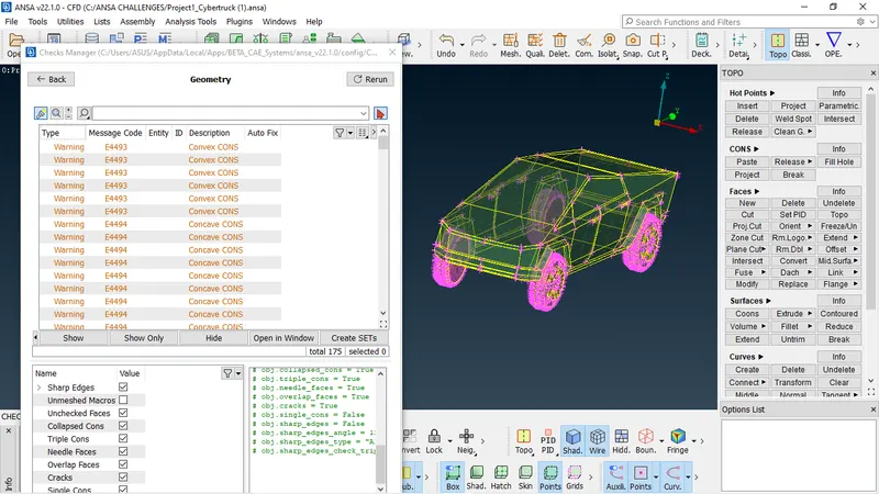
1. First of all import the given geometry to ANSA and go to check manager to see what are the errors presentin the model .
In our model, mainly intersection erros, single cons , concave cons, convex cons, mixed cons, unfill hollow were present as you can see...
2.First of all we have used Topo because there was many single cons which was not supposed to stay .And by using topo single cons convert into double cons.
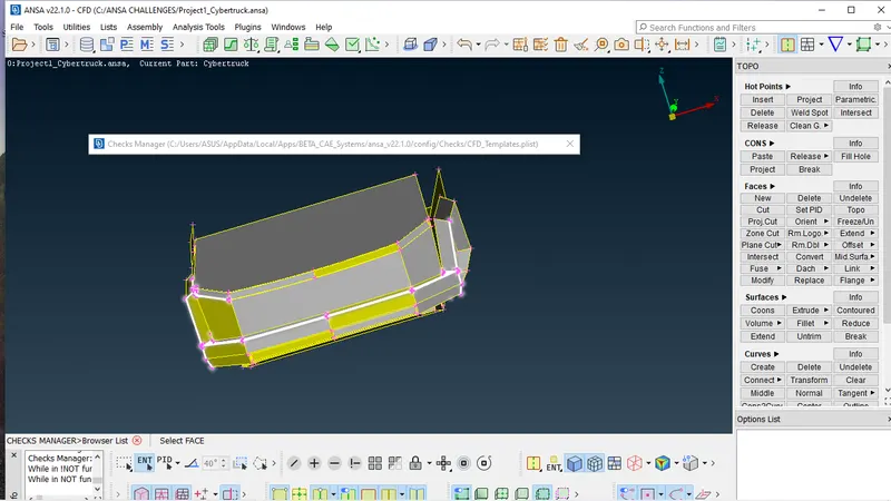
3. Then using Not, iNot , Lock option we isolated the intersection surfaces and resolved the penetration errors one by one using Intersect in Faces . And deleted the unwanted face and keep the necessary surfaces. After that we release the Lock option and go for All in order to get back the full geometry.
4. Again we go for check manager to see where the errors are present, the actual place. Then isolating the surface one by one using Universal deleted tools we deleted the overlapping surface and created the new surface where it is required using New cons, Fitted tools.
Also we can check the overlapping surfaces by enable PID mode.
5.In our geometry many concave cons, conves cons were present but in our case we can simply ignore this concave cons, convex cons. We just onlt need to resolve the penetration errors, single cons, overlapping surfaces , unnecessary triple cons and unfill surfaces.
6. In this way I have cleared all the errors.
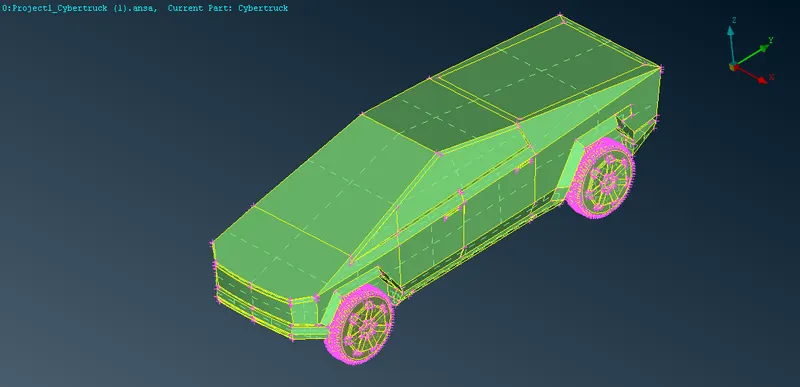
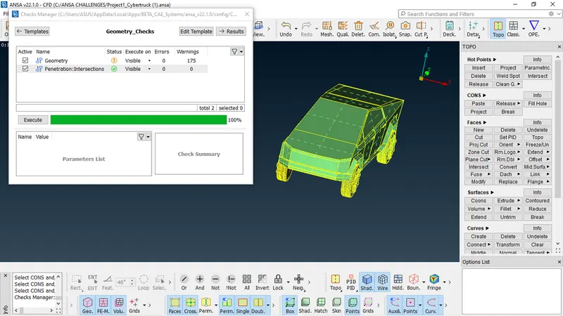
Here you can see 175 warnings of concave cons, convex cons . We can simply ignore that.
7. Now we have set the PIDs for the tyres and body using PIDs manager or set PIDs.
1.ty 1
2.ty 2
3.ty 3
4.ty 4
5.Body part 1
6.Body part 2
7.Body part 3
For tyres target length = 2 mm
For body parts target length = 3 mm
Using compress tool we deleted all the unwanted PIDs.
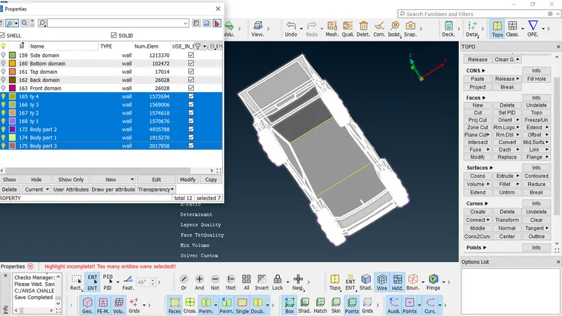
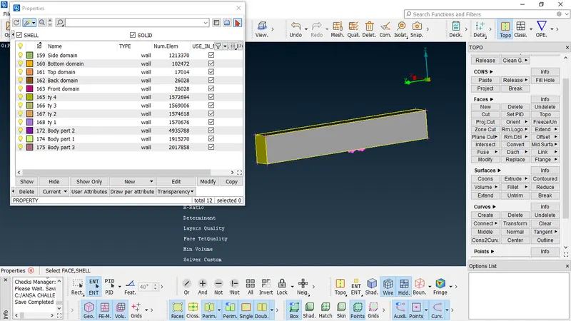
Procesure for surface meshing :-
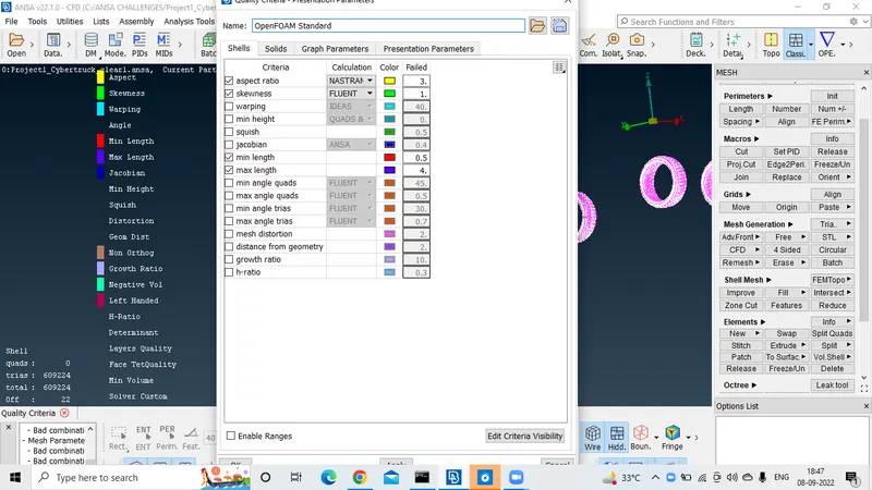
1.First we enable the tyre part from PID one by one in order to surface mesh. For tyre we have given 2 mm target length. And in order to meshing Mesh parameters, Quality criteria , Length in perimeters has been used. We enabled Aspect ratio, Skewness, min length and max length and disabled all other quality croteria.
2. Surface mesh of tyres -
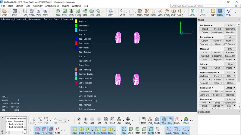
To see the off elements we enable Hidden option and here you can see 3542 off elements.
In order to clear the offelements improve, split, move etc has been used.
3. Surface mesh for body part . For body target length 3 mm
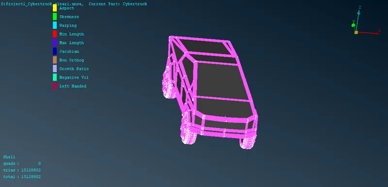
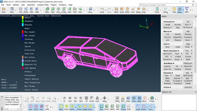
No more off elments. Also we have used freeze so that othe part stay uneffected by the other mesh length and quality criteria.
Procedure to create and mesh the wind tunnel:-
1. Before creating we need to measure the length, width and height of the car. And for the front domain 4 *length of the car and bottom domain width of the truck , distance of rear domain from model 6*length .
2. Create in curve , Relative in points has been used to create the wind tunnel.
First using Relative tools in topo we have to create a curve in y direction and then create the surface using curve tool, Fitted in New.
In this way we created the wind tunnel. Then set pids for the Top , Bottom, Side , Front and Rare domain in wind tunnel.
3. Now we meshed the winned tunnel by length 20 mm for Bottom and 100 for Top domain . And at last using spacing we meshed all the PIDs in wind tunnel . In spacing we have used Dstart = 20 and Dlimit = 100.
Snapshot of the wind tunnel :-
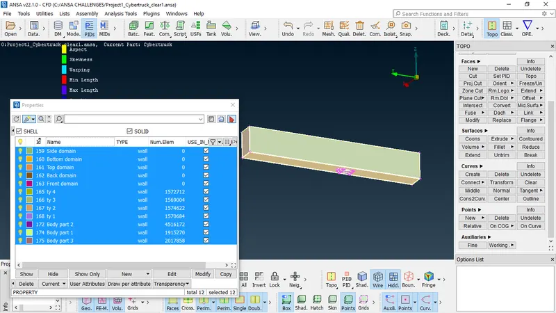
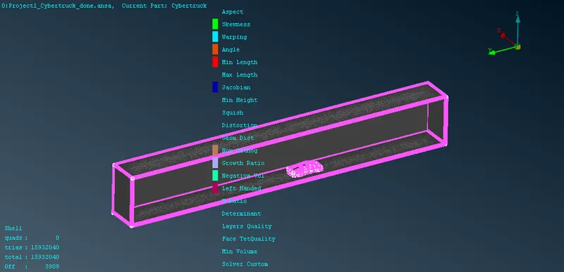
You can see there are 3909 off elements present in our geometry. But as compare to the total elements of the model 3909 is very small amount of number. So we can simply ignore this off elements.
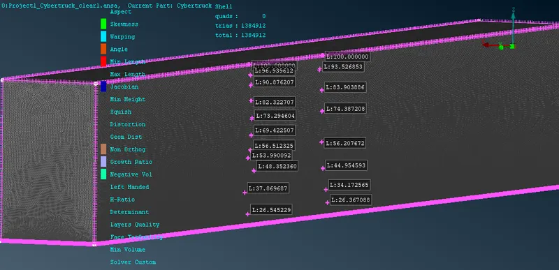
Length is increasing form 20 mm to 100 mm gradually as we have used spacing from bottom to top domain.
Link of the meshing geometry with wind tunnel :-
https://drive.google.com/file/d/14mkiB6jCQSen1VM4I00g2GBQNq0d7azW/view?usp=sharing