Week 9 - Parametric study on Gate valve.
Aim: To perform a parametric study on Gate Valve using steady-state simulation by raising the disc of the valve from 20,30,40,50,60mm.
Objective:
- Obtain the mass flow rates at the outlet for each design point.
- Calculate the flow coefficient and flow factor for each opening and plot the graph.
- Discuss the results of the mass flow rate and flow coefficient.
Introduction
A gate valve, also called sluice valve, often installed in a pipe fitting, opens by lifting a barrier called gate out of the path of the fluid. Gate valves require very little space along the pipe axis and hardly restrict the flow of fluid when the gate is fully opened. The gate faces can be parallel but are most commonly wedge-shaped.
Gate valves are used to shut off the flow of liquids rather than for flow regulation. When fully open, the typical gate valve has no obstruction in the flow path, resulting in very low flow resistance.
step 1:-
geometry
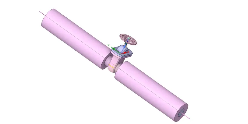
The used geometry has been adapted from the source provided. Later modifications were done for development of computational domain. Ansys SpaceClaim has been used to modify the geometry for further development.
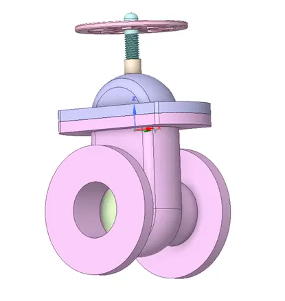
The imported geometry
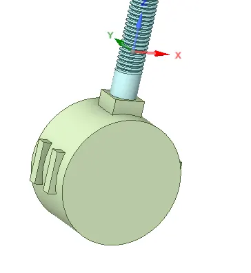
gate disc
step 2:-
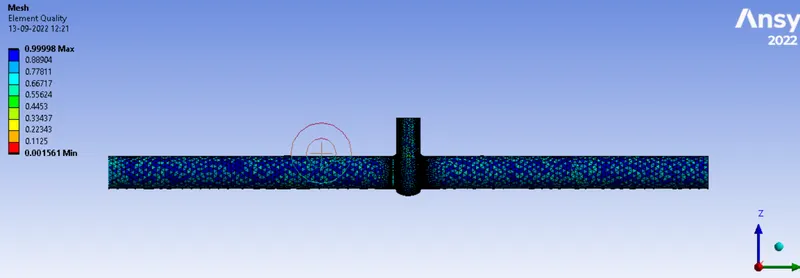
meshed geometry and its quality
step 3:-
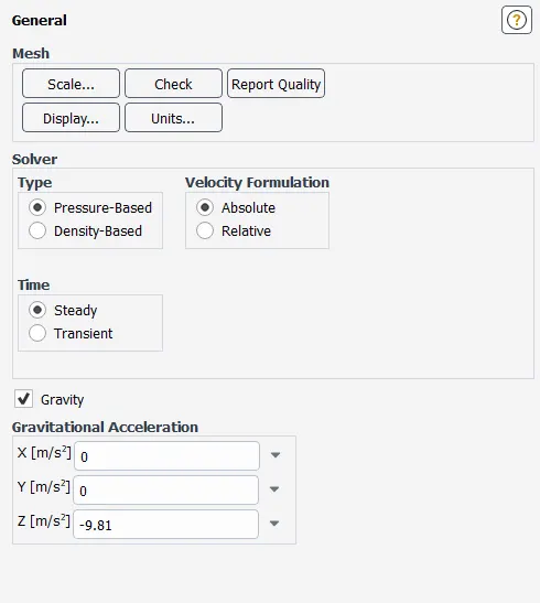
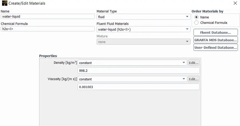
setting up the physics
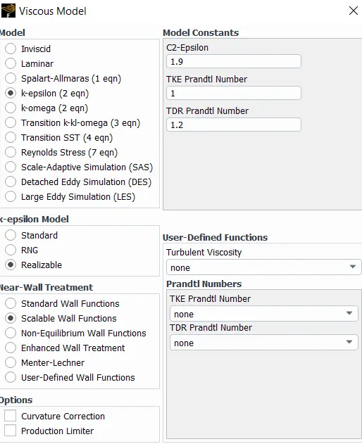
Viscous Model
Since this is a pipe flow simulation, if our goal was to employ accurate solution of near boundary values, we would have gone through modelling the boundary more precisely, here our objective is to measure the bulk flow parameter so we are going to be using K – epsilon model with scalable wall function.
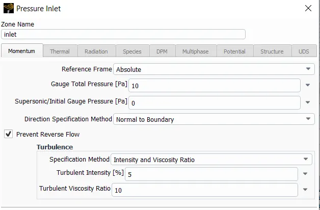
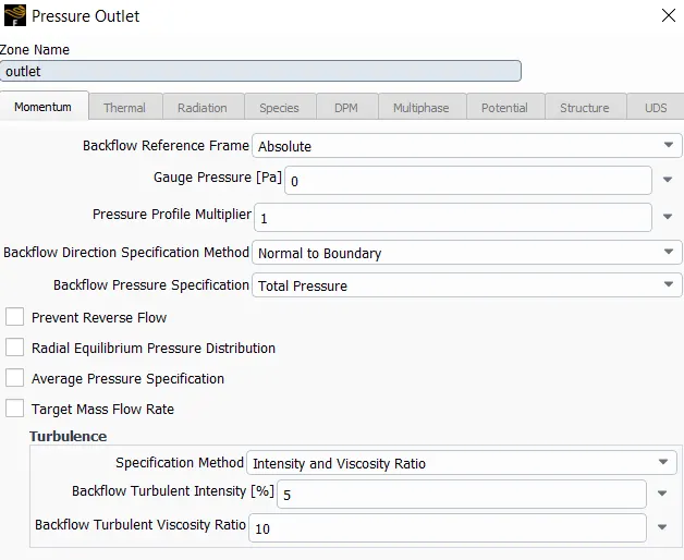
boundary conditons
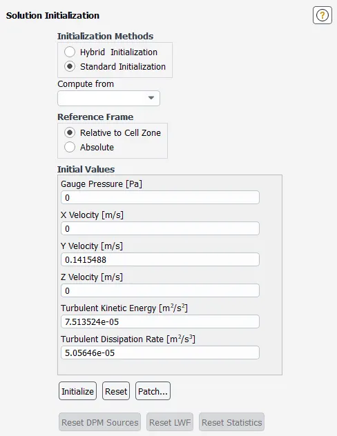
intilization of solver
results :-
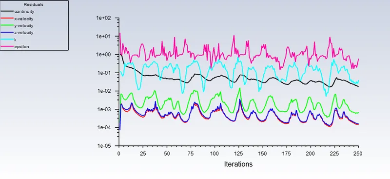
plots of residuals for the 20mm lift
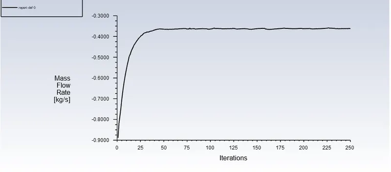
mass flow rate :-
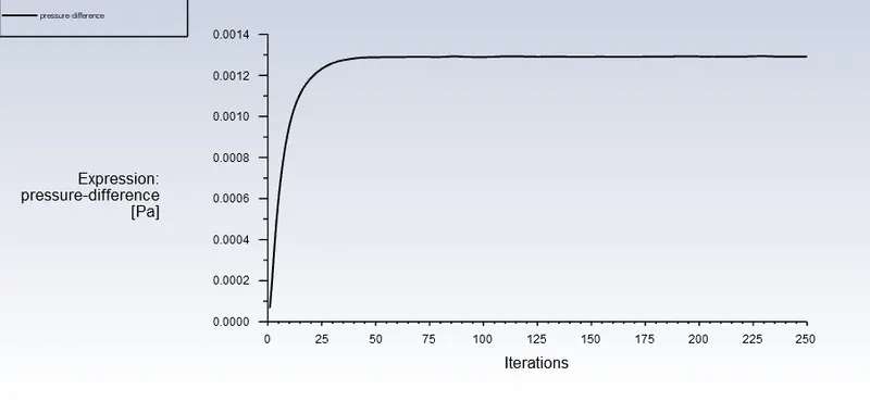
pressure difference plot:
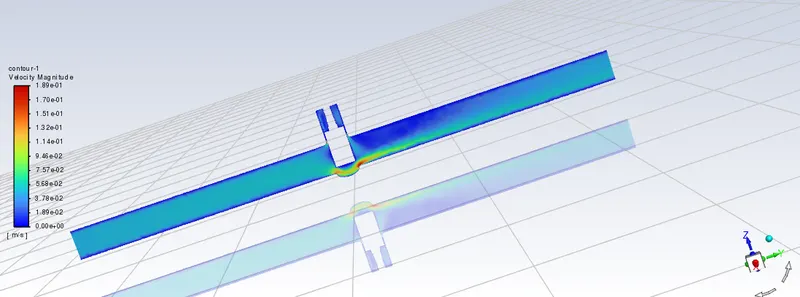
velocity contour for 20mm life
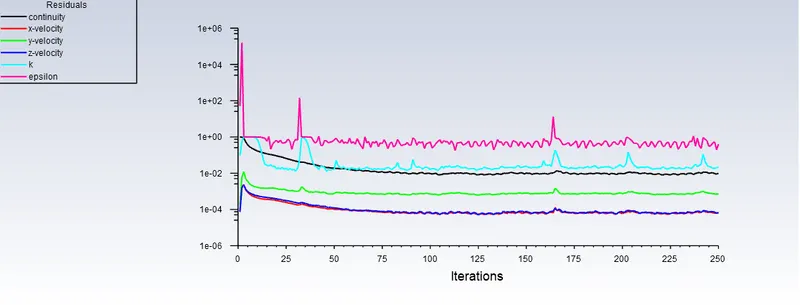
scalar residulas for 30mm lift
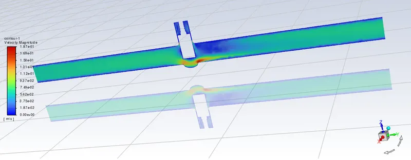
velocity contour for 30mm lift
The Parametric Values Gatherd from the simulation are:
the parametrization is done to the below mentioned gate hight in mm
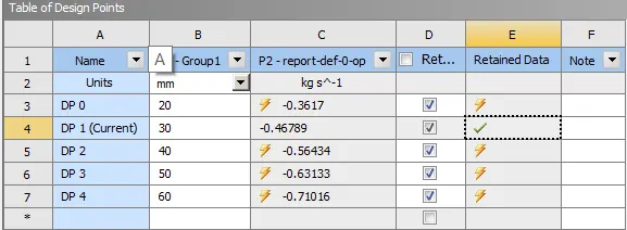
from the above table we can say the for the differnet lift of gate the mass flow rate of fluid incresed.
the results of all the DP point can be visulize bgt making that DP as "set as current point".
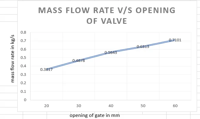
plot for the mass flow rate and opening of valve
conclusion
As can be seen from the above plot, The lower is the valve, or lesser space is there for fluid flow, low is the mass flow rate.
Aslo, lower is the valve opening higher is the pressure difference.
With increase in the valve opening, the mass flow rate also flow coefficient as well as flow factor also increases.