Week 9 - Parametric study on Gate valve.
REPORT
Gate Valve Simulation
OBJECTIVE
To perform a parametric study on the gate valve simulation by setting the opening from 10% to 80%.
ABSTRACT
This work presents a simulation for a gate valve with a parametric study showing variation in various factors like mass flow rate, flow coefficient, and flow factor for the lift of gate disc by different percentages.
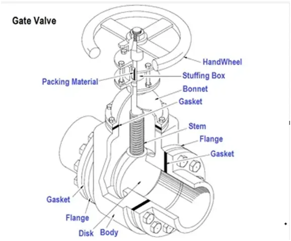
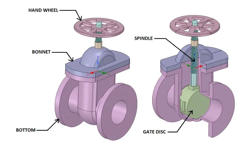
The main components of a gate valve are the body, seat, stem, bonnet, and actuator. The main operation mechanism of a gate valve is quite simple. When the hand wheel is turned, it rotates the fluid, which is translated into the vertical movement of a Gate Disc via threads. They are considered multi-turn valves as it makes more than 3600 turns to fully open/close the valve. When the gate is lifted from the path of the flow, the valve opens and when it returns to its closed position, it seals the bore resulting in a full closure of the valve.
THEORY
Gate valve
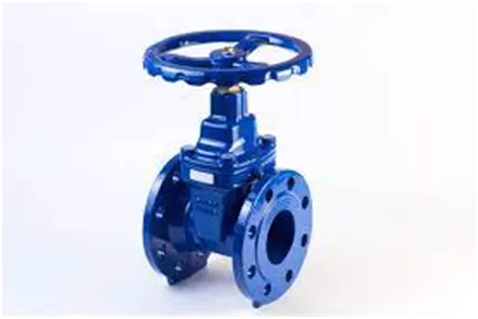
A gate valve, also known as a sluice valve, is a valve that opens by lifting a barrier out of the path of the fluid. Gate valves require very little space along the pipe axis and hardly restrict the flow of fluid when the gate is fully opened. Gate valves are widely used for all types of applications and are suitable for both above-ground and underground installation.
Construction: Common gate valves are actuated by a threaded stem that connects the actuator to the gate. They are characterized as having either a rising or a non-rising stem, depending on which end of the stem is threaded. Rising stems are fixed to the gate and rise and lower together as the valve is operated, providing a visual indication of valve position. The actuator is attached to a nut that is rotated around the threaded stem to move it. Non-rising stem valves are fixed to, and turn with, the actuator, and are threaded into the gate. They may have a pointer threaded onto the stem to indicate valve position since the gate’s motion is concealed inside the valve. Non-rising stems are used where vertical space is limited. Gate valves are typically constructed from cast iron, cast carbon steel, ductile iron, gunmetal, stainless steel, alloy steel, and forged steel.
Use: Gate valves are used to shut off the flow of liquids rather than for flow regulation. When fully open, the typical gate valve has no obstruction in the flow path, resulting in meagre flow resistance.
Parametric Study
With very little marginal work a completed model can be parameterized to stimulate scenarios limited only by computational time and resources.
As we move forward with the design, one can assess the impact that changing certain parameters can have on the design. The parameters can include dimensional parameters. A parametric study allows one to nominate parameters for evaluation, define the parameter range, specify the design constraints, and analyze the results of each parameter variation.
A parametric study requires the following:
- The design objective is to set parametric dimensions
- Parameters nominated for use in the simulation
- Parameter ranges identified
- Design criteria specified
- Various configurations generated
Once determined that a configuration satisfies the design needs, one can promote that configuration back to the model as a CAD edit. One is prompted to make changes.
Flow coefficient
The flow coefficient of a device is a relative measure of its efficiency at allowing fluid flow. It describes the relationship between the pressure drop across an orifice valve or other assembly and the corresponding flow rate.
Mathematically the flow factor Cv (or flow-capacity rating of the valve) can be expressed as:
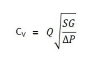
Where
- Q is the rate of flow (expressed in US gallons per minute),
- SG is the specific gravity of the fluid (for water = 1)
- /_\ P is the pressure drop across the valve (expressed in psi)
In more practical terms, the flow coefficient Cv is the volume (in US gallons) of water at 600F that will flow per minute through a valve with a pressure drop of 1 psi across the valve.
The use of the flow coefficient offers a standard method of comparing valve capacities and sizing valves for specific applications widely accepted by the industry. The general definition of the flow coefficient can be expanded into equations modelling the flow of liquids, gases and steam using the discharge coefficient.
Flow factor
The metric equivalent flow factor (Kv; commonly used in Europe and Asia) is calculated using metric units:
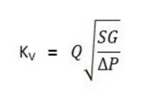
Where
- Kv is the flow factor
- Q is the flow rate (expressed in cubic meters per hour)
- SG is the gravity of the fluid (for water = 1)
- /_\P is the differential pressure across the device (expressed in bar)
Kv can be calculated from Cv using the equation given below:
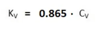
The kv factor of a value indicates ‘the water flow in m3/h, at a pressure drop across the valve of 1kgf/cm2 when the valve is completely open.
CASES
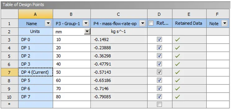
According to the opening of the valve, given as lift of ‘Gate Disc’ in mm, all 8 cases are named as given below:
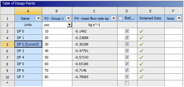
- DP 0 = 10
- DP 1 = 20
- DP 2 = 30
- DP 3 = 40
- DP 4 = 50
- DP 5 = 60
- DP 6 = 70
- DP 7 = 80
PROCEDURE TO SETUP THE CASE
Methodology
- Activate parameters at appropriate points throughout the simulation.
- Adapt fluid volume to changing solid geometry.
SpaceClaim
- Import the gate valve step file into space claim.
- Hide all the components of the gate disc except the Spindle and Gate Disc.
- Pull the pipe’s outer solid surface before extracting the fluid volume.
- Extract the fluid volume.
- Extend the fluid flow regions of the inlet and outlet by using the Pull option on the Design tab. Select inlet and outlet faces individually and drag outwards and assign the value of 800 mm on each side respectively.
- The solid geometry is suppressed for physics.
- Then from the Design tab and choose the Move option and further select Move Component and select the Gate-Disc. Following this, a Coordinate system appears on the gate disc and then proceeds to move the gate disc towards the top of the spindle.
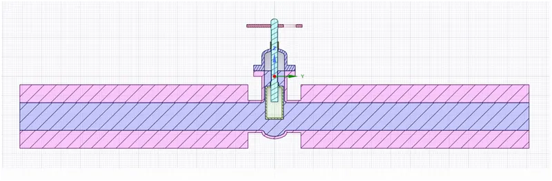
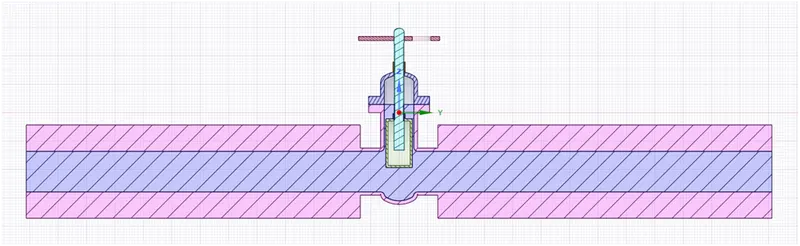
- On the Groups menu adjacent to the Structure menu, there is a Create Parameter button which gets enabled only after the gate disc is moved. Click on the Create Parameter following which a Group-1 appears in which one can edit the dimensions of the lift. Assign the ruler dimension accordingly.
- After setting the lift of the valve as a parameter, update the extracted volume as Update it as per the context. (Make sure that the bonnet is hidden while updating it within the context and the section line should not cross through the gate disc.)
Geometry
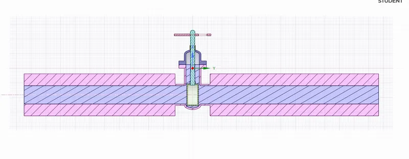
Geometry with no disc lift
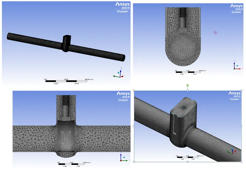
Mesh
- Name surfaces according to respective boundary conditions are created.
- Element size: 7 mm
- Statistics
Nodes 64436
Elements 315372
Mesh
Mesh Metric
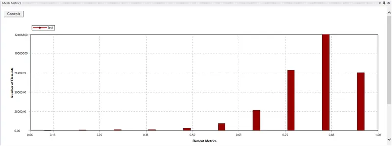
Setup
General Settings
Solver
- Type – Pressure-based
- Velocity Formulation – Absolute
- Time – Steady State
- Gravity - -9.81 m/s2 in z-direction
Viscous
- Turbulence
- k-epsilon (2 equation)
- Model – Realizable
- Near Wall Treatment – Scalable Wall Functions
Material
- Fluid Volume – Water Liquid
Chemical Formula – H2O
Density – 998.2 kg/m3
Viscosity – 0.001003 kg/(m-s)
Boundary Conditions
- Inlet
- Type: Pressure-Inlet
- Gauge Total Pressure: 10 Pa
- Outlet
- Type: Pressure-Outlet
- Gauge pressure – zero Pa
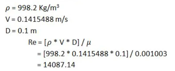
Note: The choice for the k-epsilon viscous model is made according to the characteristic of the flow i.e. turbulent flow. For Reynolds numbers about 2000 and more, the flow becomes turbulent.
Solution
- Use definitions to plot important parameters.
- Define necessary contours for tracking the result.
- Initialization using Standard as the inlet and outlet boundary conditions can be seen.
- Standard initialization is done with assigned values computed from the inlet.
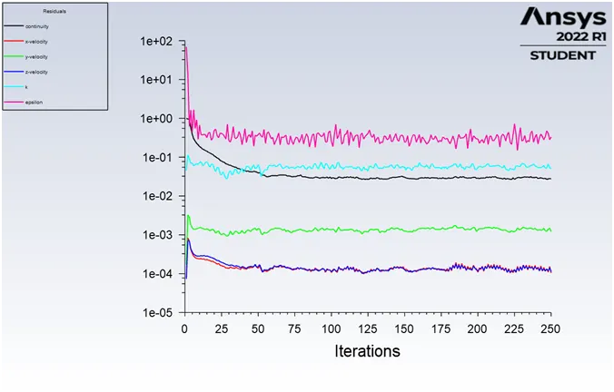
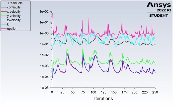
- Calculating with 250 iterations
CFD Post
After setting up the case and providing appropriate initial and boundary conditions, several simulations are performed on the domain. For analysis, the resulting plane can be created to view measuring parameters.
Parameters
- Create a report for the mass flow rate and create that as an output parameter. (Use the Coupled solver with all factors using the first-order upwind, if facing issues with the mass-flow rate excitation)
- Just add one parameter at the start. Update that and retain that parameter. (Don’t change the current reference fixed in the parametric window)
- After getting a valid mass-flow rate output concerning the lift value, add as many parameters as needed and select all-new parameters and update those.
OUTPUT
- DP 0
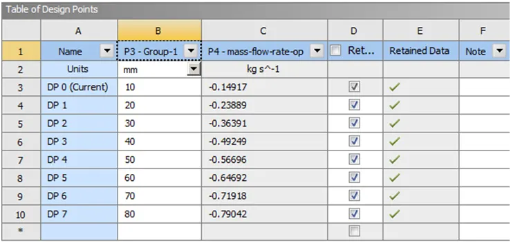
Parameters
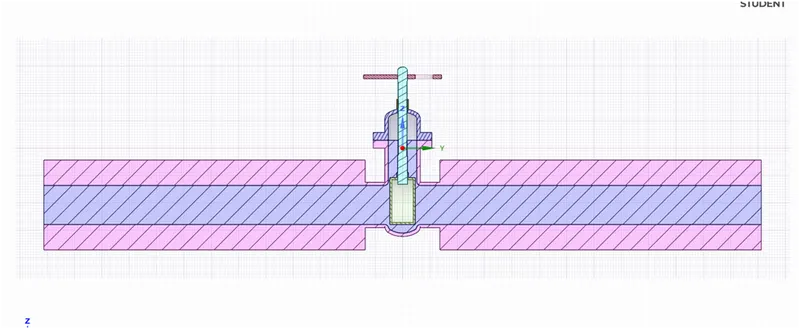
Geometry with 10 mm disc lift
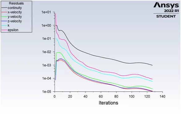
Residuals
Mass flow rate
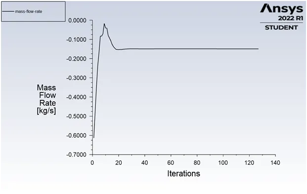
Mass flow rate value

Velocity Contour
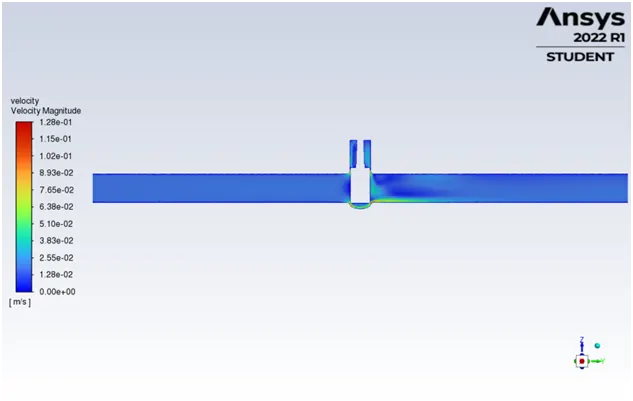
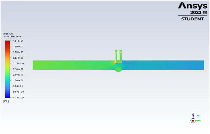
Pressure Contour
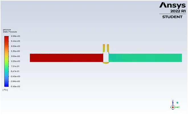
Animation
Flow Coefficient and Flow Factor
- Q = 0.1492
- SG = 1 for water
- `/_\P` = 10 psi
- Note: Here, Total Outlet pressure in Pascal is a very small value, and for converting from Pascal to psi unit, we have to multiply it by 0.000145037, which will become a negligible value as compared to 0.
- So, we can take the Pressure at the outlet as 0.
- So the pressure at Inlet is 10 and the Pressure difference mentioned here becomes 10.
`Cv = 0.1492 * sqrt (1/10)`
`Cv = 0.04718`
`Kv = 0.865 * Cv`
`Kv = 0.04081`
- DP 1
Parameters
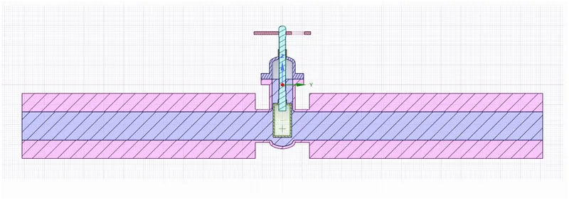
Geometry with 20 mm disc lift
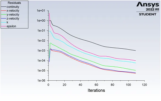
Residuals
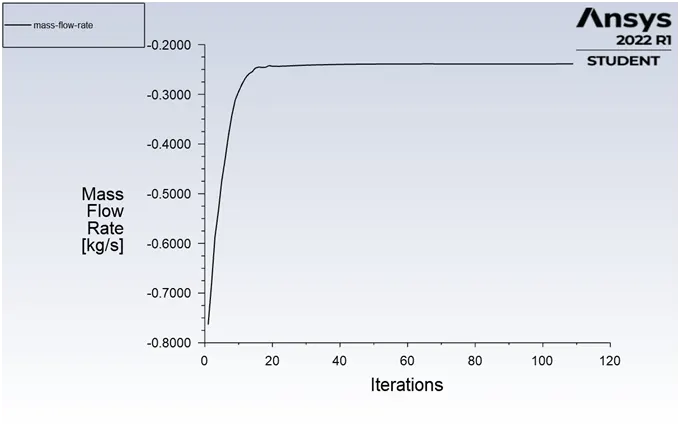
Mass flow rate
Mass flow rate value

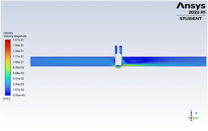
Velocity Contour
Pressure Contour
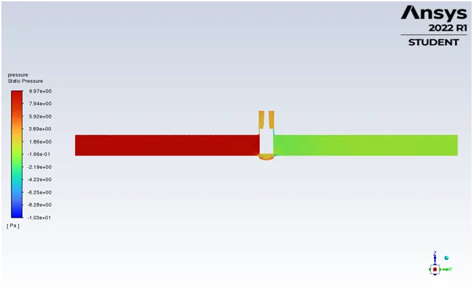
Animation
Flow Coefficient and Flow Factor
- Q = 0.23888
- SG = 1 for water
- `/_\P` = 10 psi
`Cv = 0.23888 * sqrt (1/10)`
`Cv = 0.07554`
`Kv = 0.865 * Cv`
`Kv = 0.06534`
- DP 2
Parameters
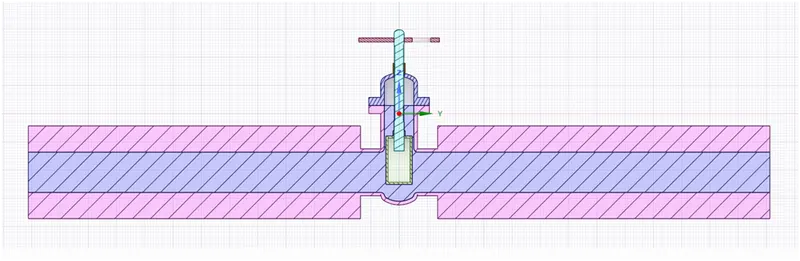
Geometry with 30 mm disc lift
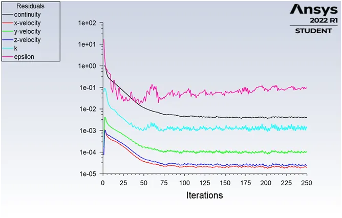
Residuals
Mass flow rate
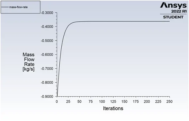
Mass flow rate value

Velocity Contour
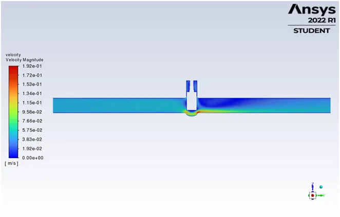
Pressure Contour
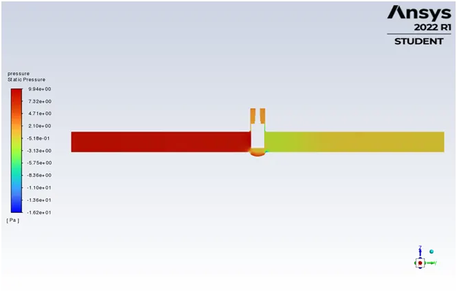
Animation
Flow Coefficient and Flow Factor
- Q = 0.36298
- SG = 1 for water
- `/_\P` = 10 psi
`Cv = 0.36298 * sqrt (1/10)`
`Cv = 0.11478`
`Kv = 0.865 * Cv`
`Kv = 0.09928`
- DP 3
Parameters
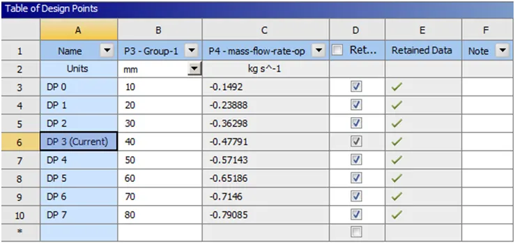
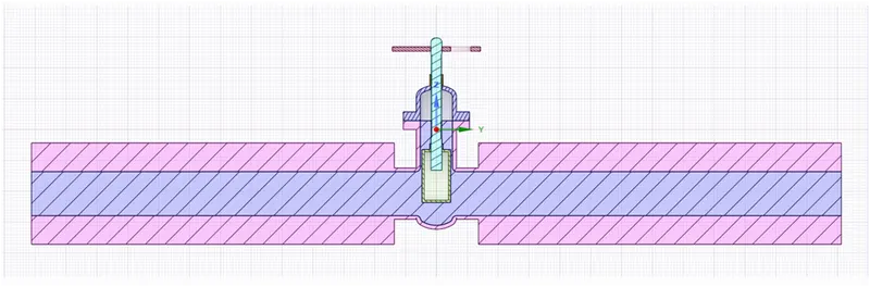
Geometry with 40 mm disc lift
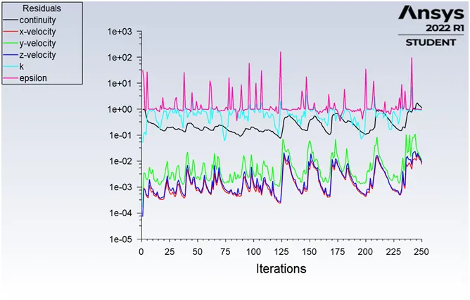
Residuals
Mass flow rate
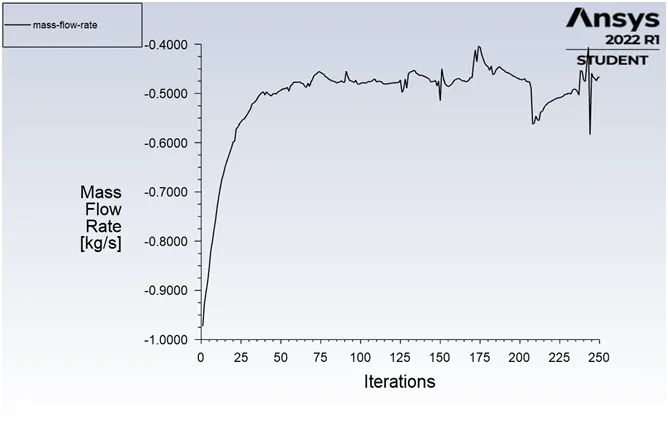
Mass flow rate value

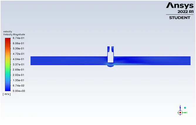
Velocity Contour
Pressure Contour
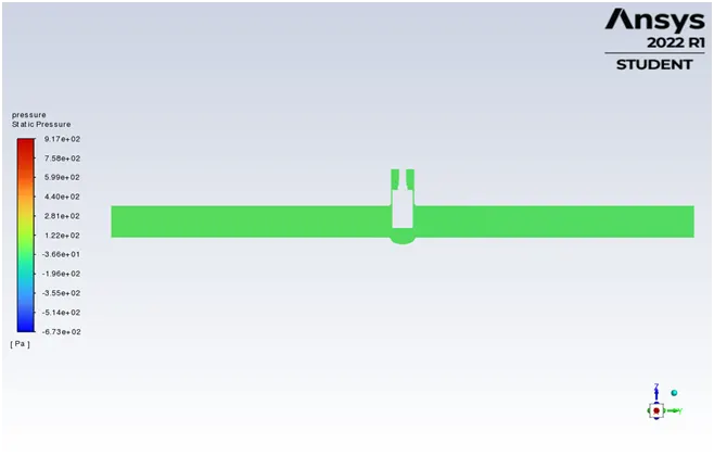
Animation
Flow Coefficient and Flow Factor
- Q = 0.47791
- SG = 1 for water
- `/_\P` = 10 psi
`Cv = 0.47791 * sqrt (1/10)`
`Cv = 0.15112`
`Kv = 0.865 * Cv`
`Kv = 0.13072`
- DP 4
Parameters
Geometry with 50 mm disc lift
Residuals
Mass flow rate
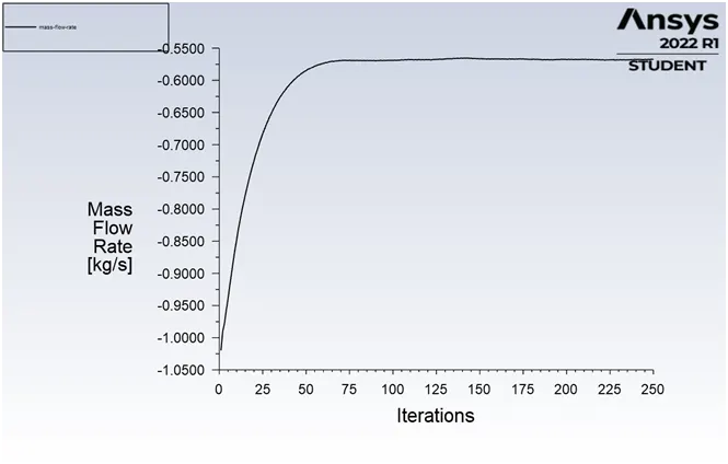
Mass flow rate value

Velocity Contour
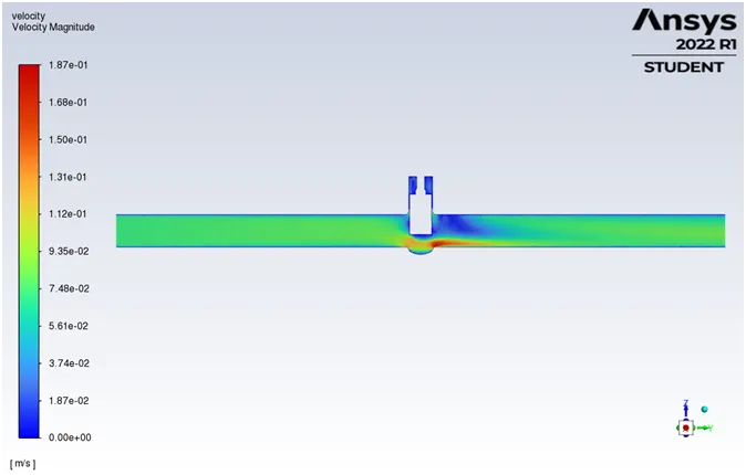
Pressure Contour
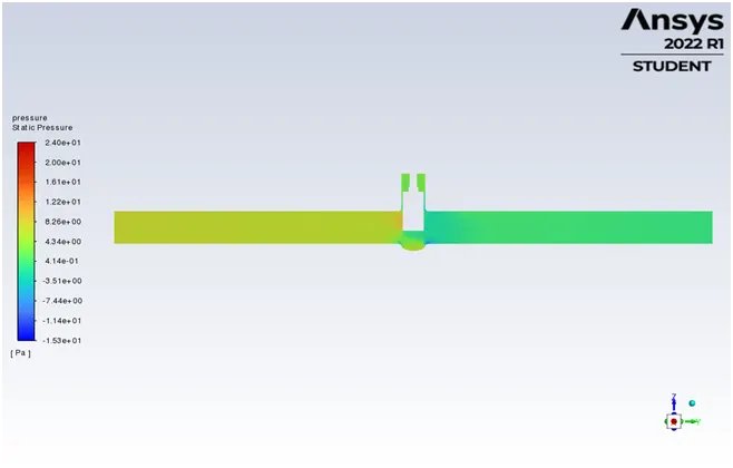
Animation
Flow Coefficient and Flow Factor
- Q = 0.57143
- SG = 1 for water
- `/_\P` = 10 psi
`Cv = 0.57143 * sqrt (1/10)`
`Cv = 0.18070`
`Kv = 0.865 * Cv`
`Kv = 0.1563`
- DP 5
Parameters
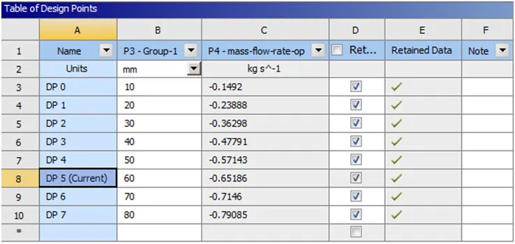
Geometry with 60 mm disc lift
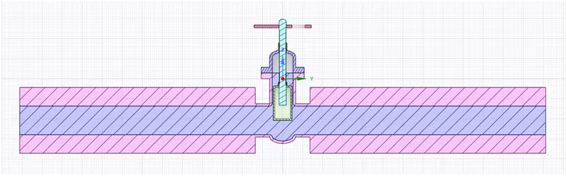
Residuals
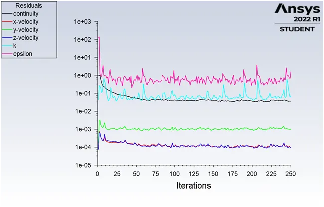
Mass flow rate
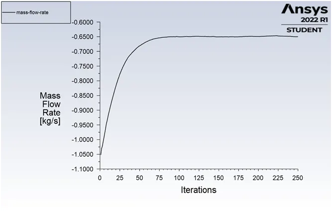
Mass flow rate value

Velocity Contour
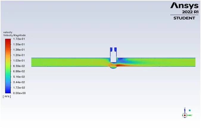
Pressure Contour
Animation
Flow Coefficient and Flow Factor
- Q = 0.65186
- SG = 1 for water
- `/_\P` = 10 psi
`Cv = 0.65186 * sqrt (1/10)`
`Cv = 0.20613`
`Kv = 0.865 * Cv`
`Kv = 0.1783`
- DP 6
Parameters
Geometry with 70 mm disc lift
Residuals
Mass flow rate
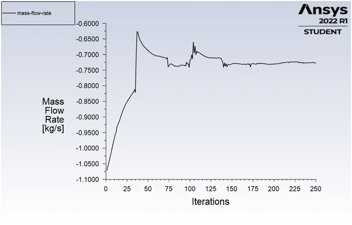
Mass flow rate value

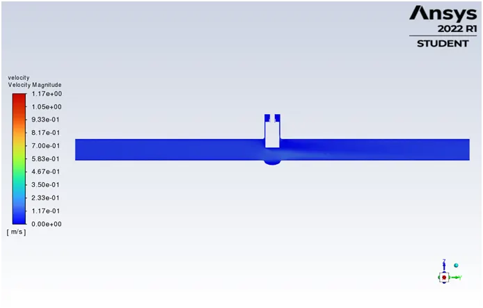
Velocity Contour
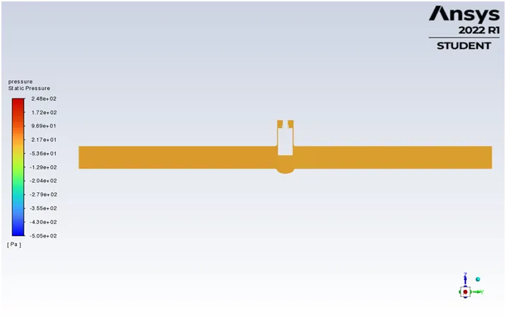
Pressure Contour
Animation
Flow Coefficient and Flow Factor
- Q = 0.7146
- SG = 1 for water
- `/_\P` = 10 psi
`Cv = 0.7146 * sqrt (1/10)`
`Cv = 0.22597`
`Kv = 0.865 * Cv`
`Kv = 0.195469`
- DP 7
Parameters
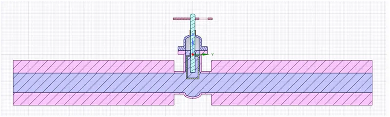
Geometry with 80 mm disc lift
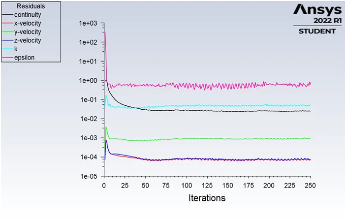
Residuals
Mass flow rate
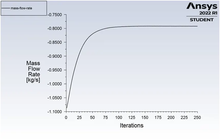
Mass flow rate value

Velocity Contour
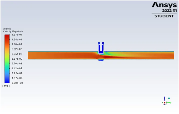
Pressure Contour
Animation
Flow Coefficient and Flow Factor
- Q = 0.79085
- SG = 1 for water
- `/_\P` = 10 psi
`Cv = 0.79085 * sqrt (1/10)`
`Cv = 0.25`
`Kv = 0.865 * Cv`
`Kv = 0.216326`
OBSERVATIONS
Reynolds Number
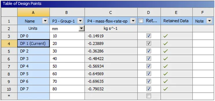
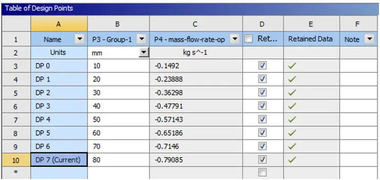
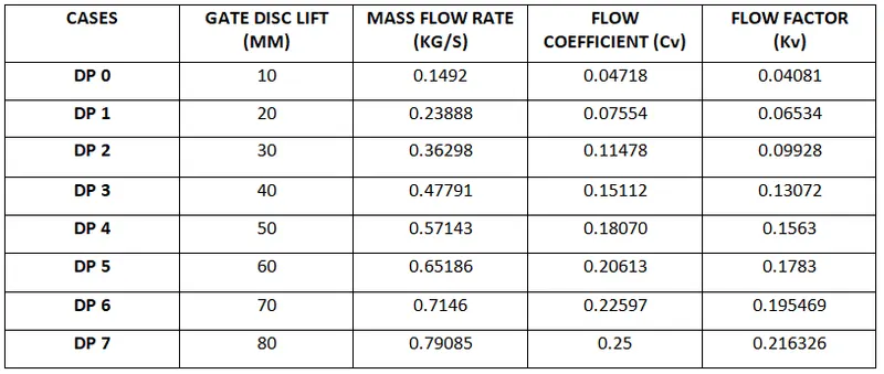
Tabular Data
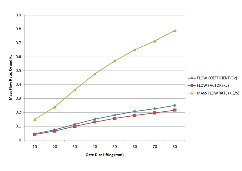
Combined graph of Gate Disc Lifting vs Mass flow rate, Cv and Kv
CONCLUSION
- From the tabular data, we can observe
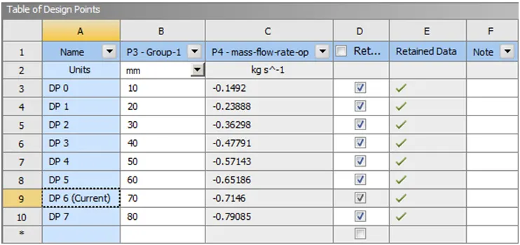
- The mass flow rate gradually increases as the lift of the gate disc is increased.
- With the increases in mass flow rate, there is an increment in both flow coefficient and flow factor.
- As the percentage of Gate Disc lift increases, the velocity of the flow increases.
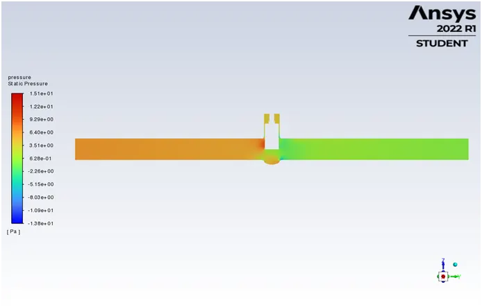
- At the inlet side of the valve, pressure is high. As flow passes through the valve opening, it decreases.
- Due to no resistance at the outlet, the pressure becomes zero resulting in minimum pressure drop.
- There is a subsequent increase in Mass Rate, Flow Coefficient and Flow Factor as the Gate Disc is gradually lifted from 10mm to 80mm.
- When the valve is fully opened, Mass Flow Rate, Flow Coefficient and Flow Factor become maximum.
- Thus, parametric study helps to analyze the different positions of valve opening and gives the benefit to get easy and quick results. A parametric study is a time-reducing option when studying the effects of changes in certain parameters on a system.
REFERENCES
- https://en.wikipedia.org/wiki/Gate_valve
- https://hardhatengineer.com/gate-valve-types-parts/
- http://www.ijirst.org/articles/IJIRSTV3I10075.pdf
- https://en.wikipedia.org/wiki/Flow_coefficient
- https://tameson.com/gate-valve.html
- https://www.avkvalves.eu/en/insights/product-insights/gate-valves/what-is-a-gate-valve