Week 9 - Parametric study on Gate valve.
A PARAMETRIC STUDY ON GATE VALVE
INTRODUCTION
Gate valve
A gate valve is a valve that opens by lifting a barrier/gate out of the path of the fluid. Gate valves require very little space along the pipe axis and hardly restrict the flow of fluid when the gate is fully opened. The gate faces can be parallel but are most commonly wedge-shaped (in order to be able to apply pressure on the sealing surface).
Gate valves are used to shut off the flow of liquids rather than for flow regulation. When fully open, the typical gate valve has no obstruction in the flow path, resulting in very low flow resistance.
The size of the open flow path generally varies in a nonlinear manner as the gate is moved. This means that the flow rate does not change evenly with stem travel. Depending on the construction, a partially open gate can vibrate from the fluid flow
Gate valves are mostly used with larger pipe diameters since they are less complex to construct than other types of valves in large sizes. At high pressures, friction can become a problem. As the gate is pushed against its guiding rail by the pressure of the medium, it becomes harder to operate the valve. Large gate valves are sometimes fitted with a bypass controlled by a smaller valve to be able to reduce the pressure before operating the gate valve itself.
OBJECTIVE-
- Simulate the fluid flow through a the valve
- Obtain the mass flow rates at the outlet for each design point
- to perform a parametric study on the gate valve simulation by setting the opening from 10 % to 80%.
- Calculate the flow coefficient and flow factor for each opening.
1-Parametric study
Parameter optimisation provides a number of variation without the need to remodel your FE analysis. Geometrical, mesh properties and their effect on stress, strain, thermal or vibration analysis can be individually optimised with parameter set
A parameter is defined as a numerical or other measurable factor forming one of a set that defines a system or sets of conditions of its operation. Parameters are elements of a system that are useful or critical to identifying a system or evaluating a system’s performance, status, or condition. As an example, parameters of an equation modeling movement could include the mechanics, masses, dimensions and shapes, and densities and viscosities of fluids within the system.
- These results need to post-processed in order to find the optimal solution or compromise in an overall design
2-Flow Coeifficient
The flow coefficient of a device is a relative measure of its efficiency at allowing fluid flow. It describes the relationship between the pressure drop across an orifice valve or other assembly and the corresponding flow rate.
Mathematically the flow coefficient Cv or flow-capacity rating of valve can be expressed as ,
`Cundersetv``=Qsqrt((SG)/(DeltaP))`
where:
Q is the rate of flow (expressed in US gallons per minute),
SG is the specific gravity of the fluid (for water = 1),
ΔP is the pressure drop across the valve (expressin psi)
The use of the flow coefficient offers a standard method of comparing valve capacities and sizing valves for specific applications that is widely accepted by industry. The general definition of the flow coefficient can be expanded into equations modeling the flow of liquids, gases and steam using the discharge coefficient.
3-Flow factor
The metric equivalent flow factor (Kv) is calculated using metric units ,
`Kunderset(v)``=Qsqrt((SG)/(DeltaP)`
Kv can be calculated from Cv using the equation.
`Kundersetv``= 0.865.Cundersetv`
The kv factor or value as it is also called is defined in VDI/VDE Richtlinien No. 2173.A simplified version of the definition is the kv factor of a valve indicates "The water flow in m3/h, at a pressure drop across the valve of 1 kgf/cm2 when the valve is completely open. The complete definition also says that the flow medium must have a specific gravity of 1000 kg/m3 and a kinematic viscosity of 10−6 m2/s. e.g. water.
Pre-processing and solver setup
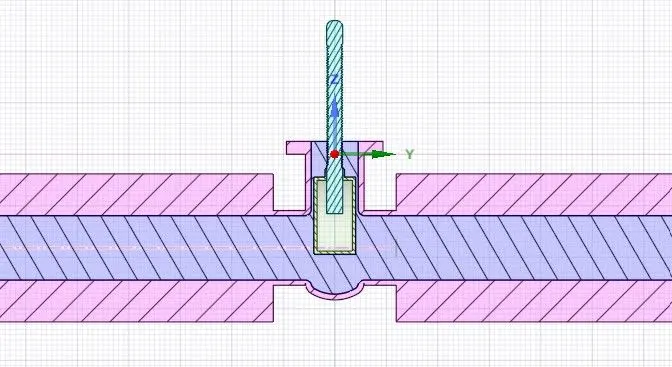
Spaceclaim geometry
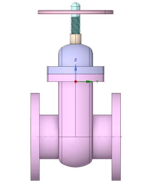
Initial lift
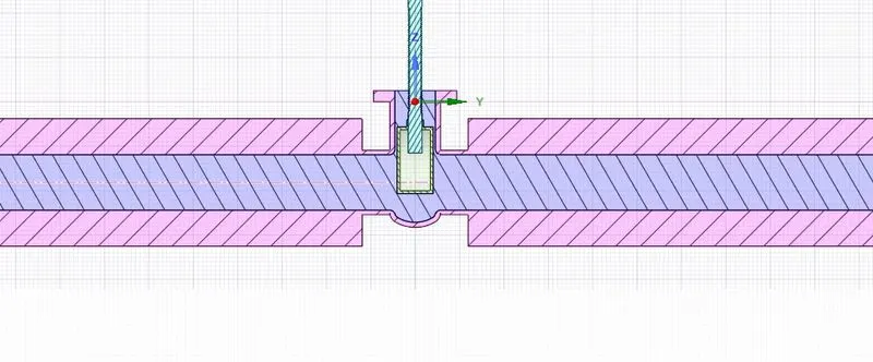
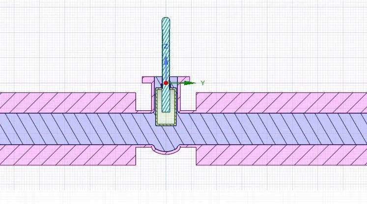
-Hide the bottom part and by using move tool move the "gate disk' 10mm upward ,after the lift we can chose the parametric option after tha the group for lift has been created(where we can change the value of lift).
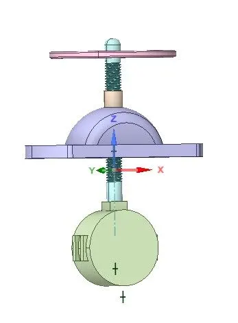
Fluid volume
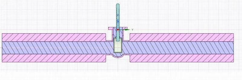
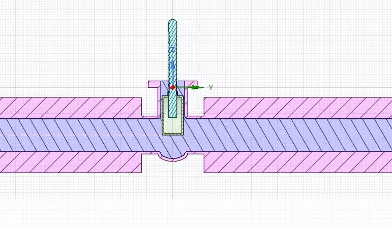
To analysis the fluid flow we increses the pipe from inlet and outlet by 800mm.
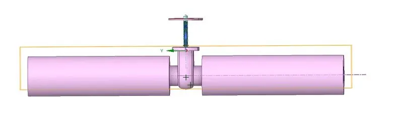
After extension Fluid volume
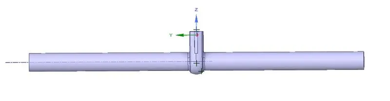
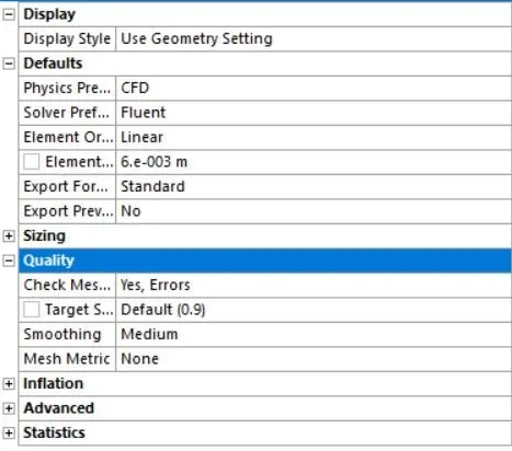
Mesh setting
The mesh
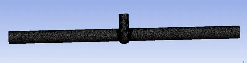
Mesh quality
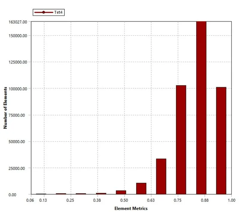
Simulation setup in fluent
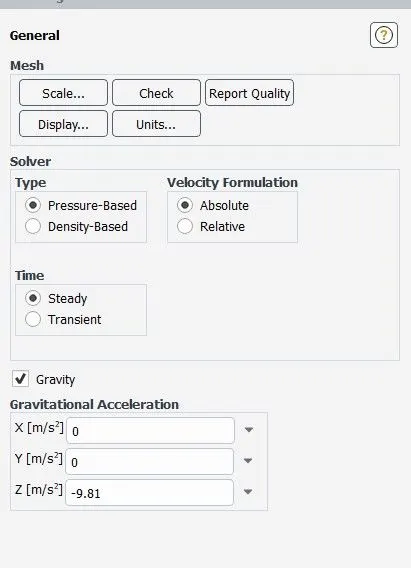
i-Solver setup
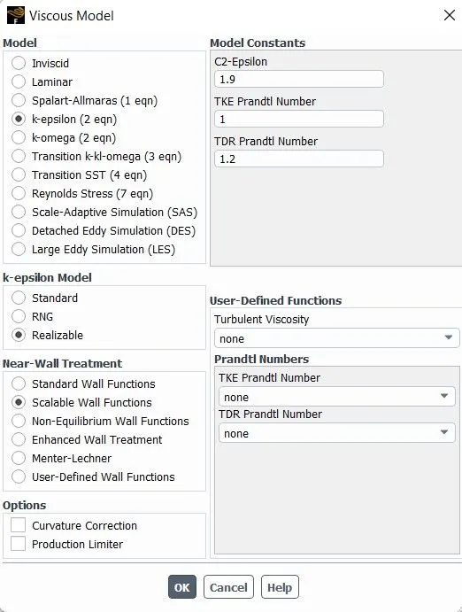
ii-Tubulance model
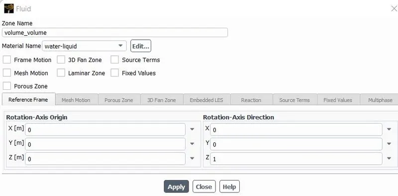
iii-Cell zone condition
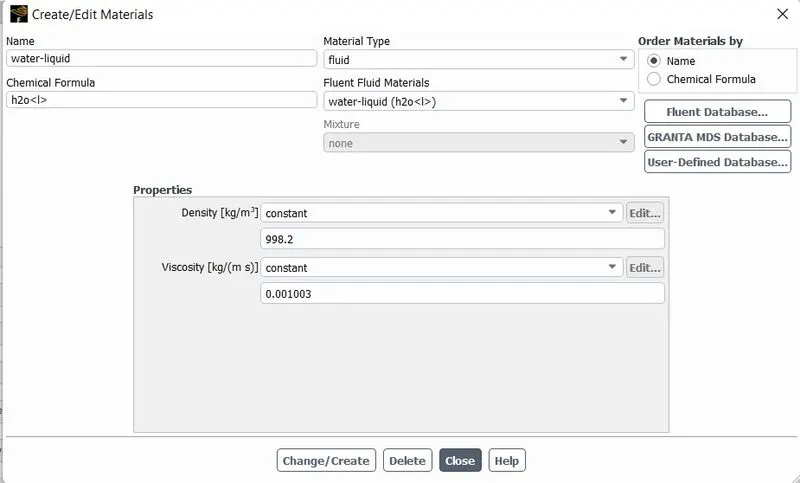
iv-material specification
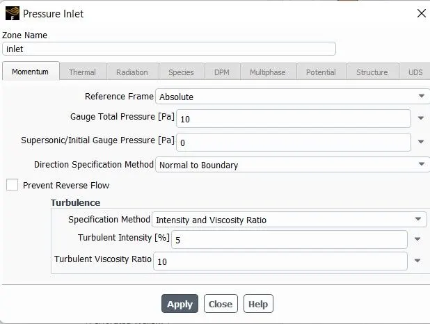
v-boundaries
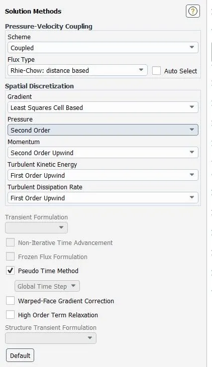
vi-Solution method
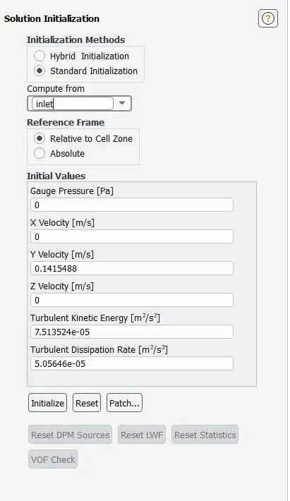
v-Initialization
RESULTS
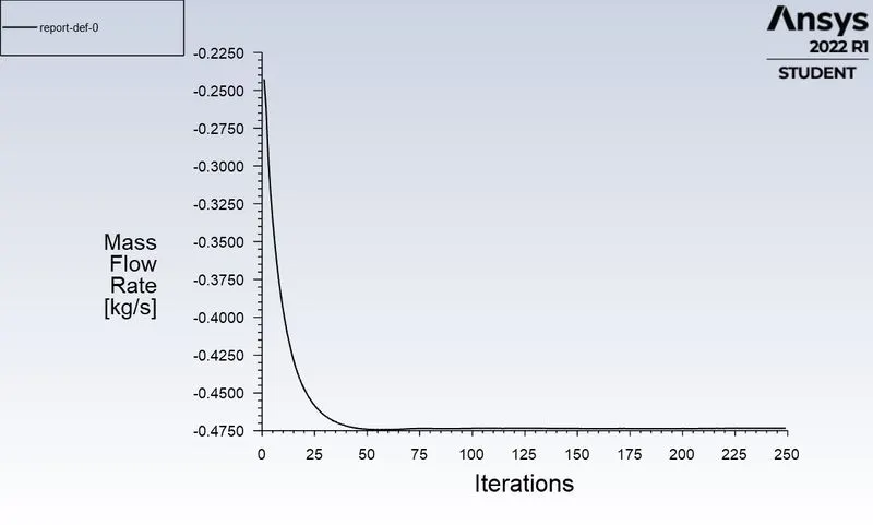
1-Parametric study of mass flow rate
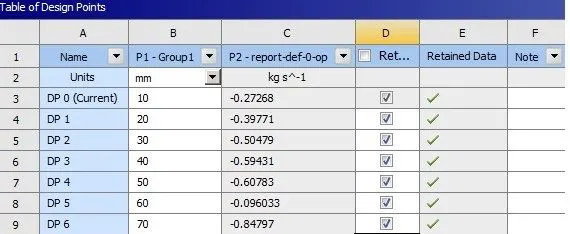
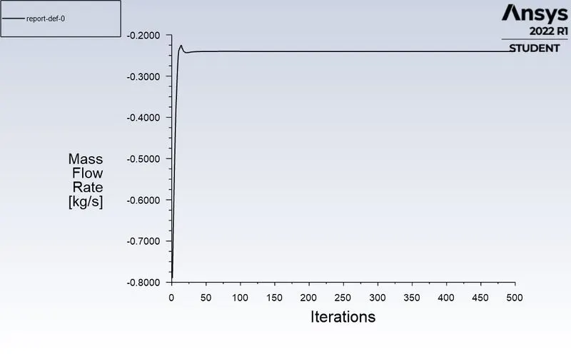
TABLE-1(FOR ALL THE CASES WE HAVE STIMULATED)
|
Lift of gate disc in mm |
Mass flow rate (kg/s) |
Flow coefficient (Cv) |
Flow factor (kv) |
|
10 |
0.27268 | 0.086228 | 0.074587 |
|
20 |
0.39771 | 0.125768 | 0.108789 |
|
30 |
0.50479 | 0.159628 | 0.1380782 |
|
40 |
0.59431 | 0.187936 | 0.1625646 |
|
50 |
0.60783 | 0.192212 | 0.1662633 |
|
60 |
0.096033 | 0.0303730 | 0.0262726 |
|
70 |
0.84797 | 0.261510 | 0.2262061 |
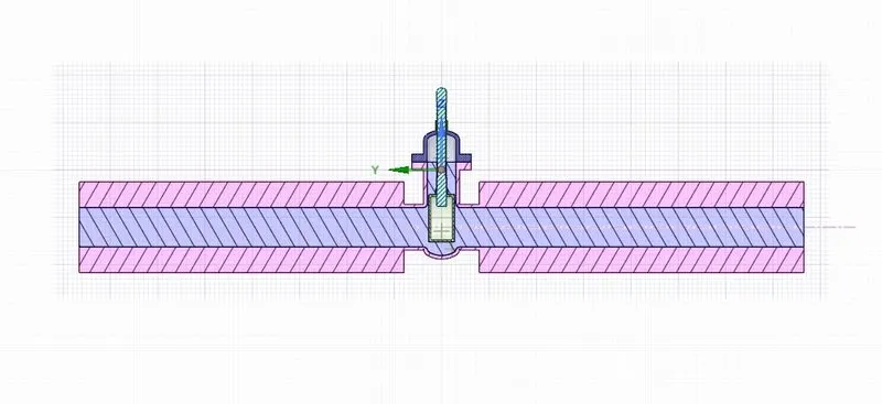
Case-1
Lift-10mm
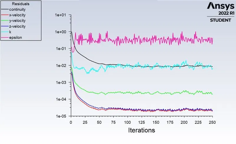
Residuals
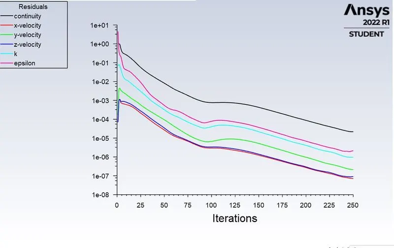
Mass Flow rate
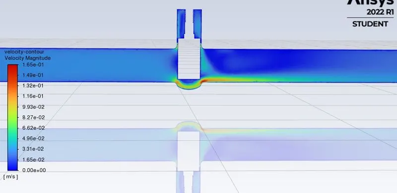
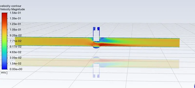
velocity contour
Case-2
Lift-20mm
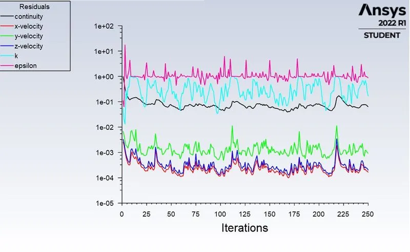
Residuals
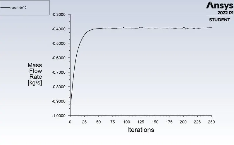
Mass Flow rate
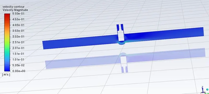
velocity contour
Case-3
Lift-30mm
Residuals
Mass Flow rate
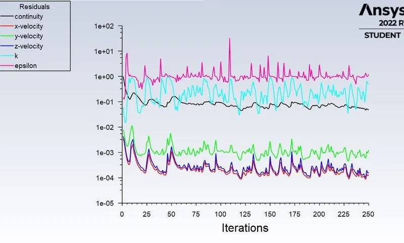
Case-4
Lift-40mm
Residuals
Mass Flow rate
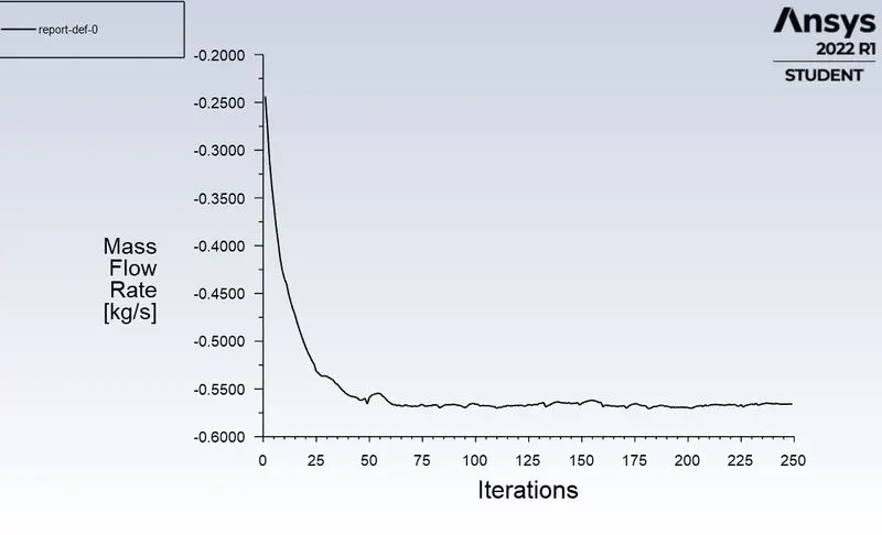
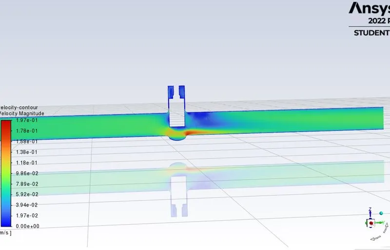
Velocity contour
Case-5
Lift-50mm
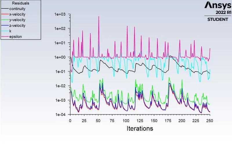
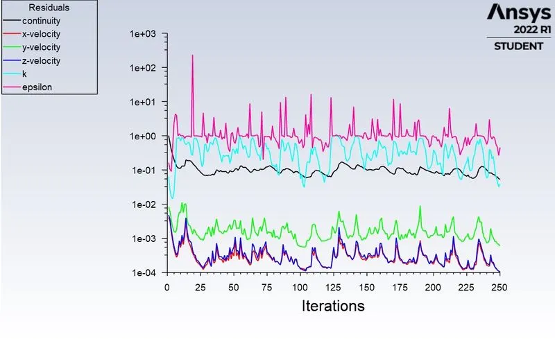
Residuals
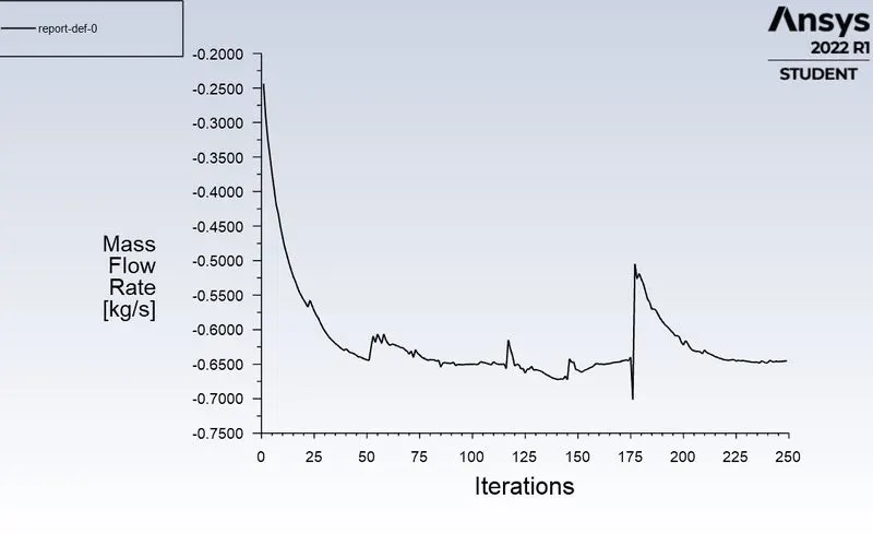
Mass Flow rate
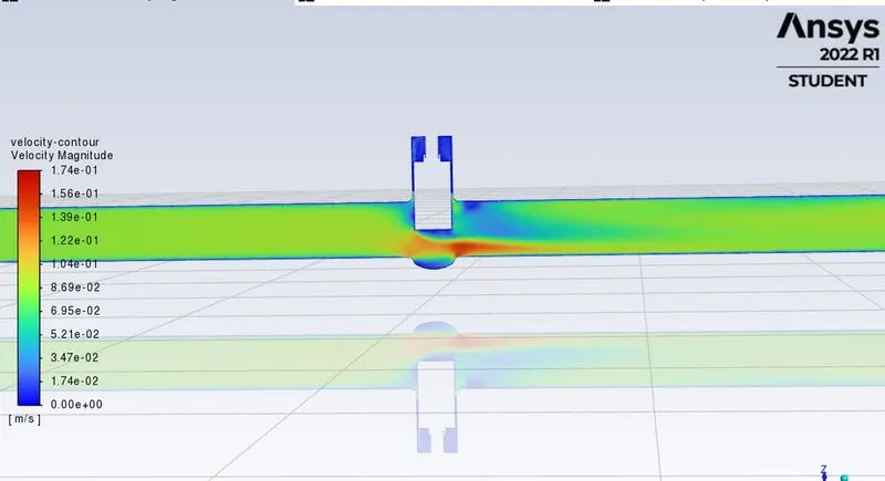
Velocity Contour
Case-6
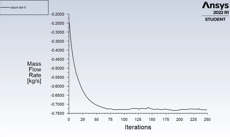
Lift-60mm
Residuals
Mass Flow rate
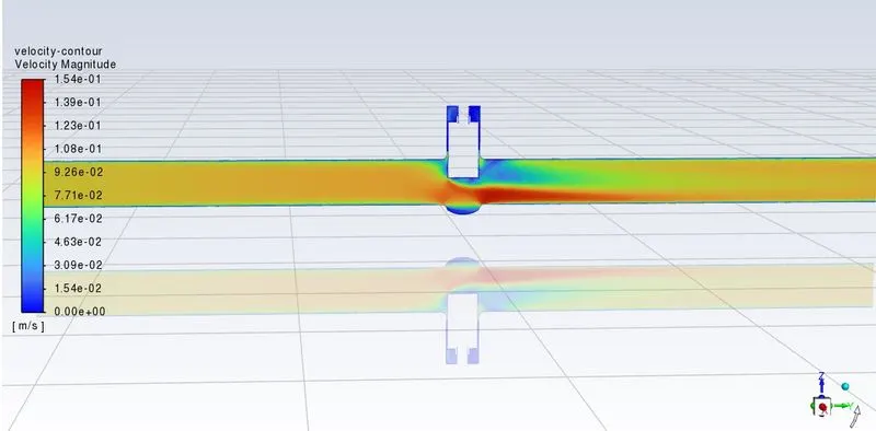
Velocity contour
Case-7
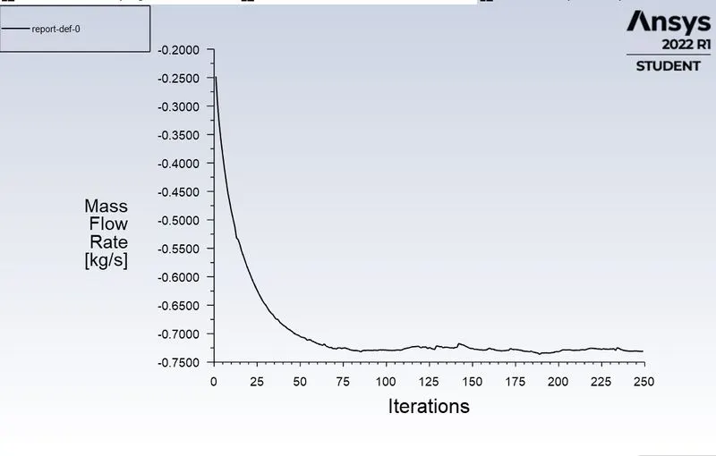
Lift-70mm

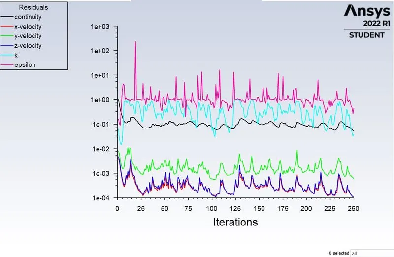
Residuals
Mass Flow rate
Velocity contour
CONCLUSION
Fom the above all the simulation we conclude that the mass flow rate increses with incresing lift of the disk, the flow factor and flow coeficent with each other.
-Velocity increses ass we increse lift of the gate valve.
-Parametric study helps to analyze the different position of valve opening and gives the benifit to get quick result