Week 9 - Parametric study on Gate valve.
OBJECTIVE: To perform parametric study on gate vale by varying the opening of the gate disc.
THEORY:
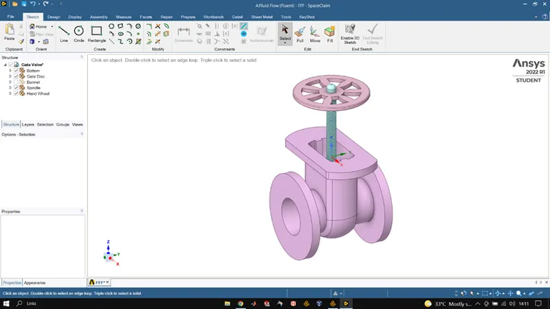
A gate valve controls the flow of fluid by varying the opening of the gate disc. The opening is varied by either lifting the gate disc or lowering the gate by use spindle. When the gate is fully opened then there is no restriction to the flow of fluid and hence the drop of pressure between inlet and outlet is very low but in case where the gate is fully closed there in no flow of fluid through the valve and the pressure drop between the inlet and outlet is significant. A gate valve consists of bonnet, gate, stem, seat, spindle and handwheel which is rotated to move the gate disc.
They are usually used to shut off the flow of liquids rather than for flow regulation.
Flow coefficient, of a device is a relative measure of its efficiency at allowing fluid flow. It describes the relationship between the pressure drop across an orifice valve and other assembly and the corresponding flow rate. Mathematically the flow coefficient Cv is expressed as,
`Cv = Qsqrt((SG)/(DeltaP))`
Flow factor, is calculated as 0.865 times of flow coefficient, it indicates the water flow in meter cube per hour at a pressure drop across the valve of 1kgf/cm2 when the valve is completely open.
`Kv = Qsqrt((SG)/(DeltaP))`
PROCEDURE:
GEOMETRY
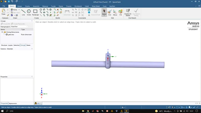
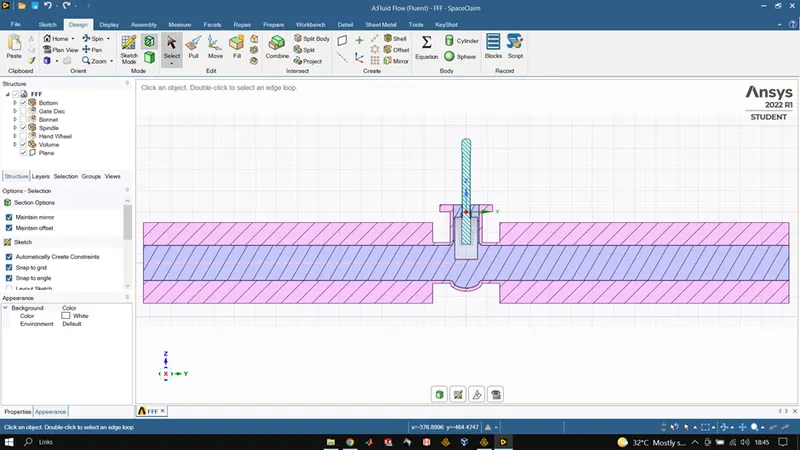
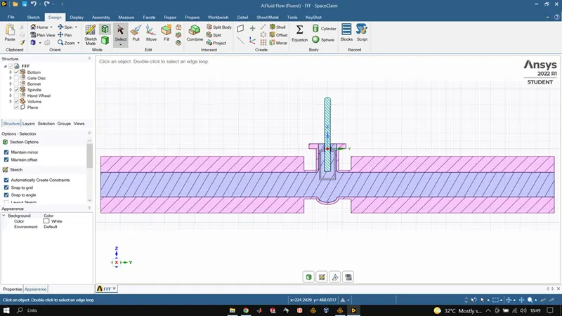
The 3d model of the gate valve is loaded and then we use the volume extract tool to extract the fluid flow volume. After that we use the pull tool to extend the bottom openings of the valve by 800mm so there is a slight visualization of the valve being connected to a pipe. After that we use the move tool to move the gate disc and move it by 10mm and in the groups on the left panel we create a parameter for this distance and name it gate-disc. Once done we close space-claim.
MESHING
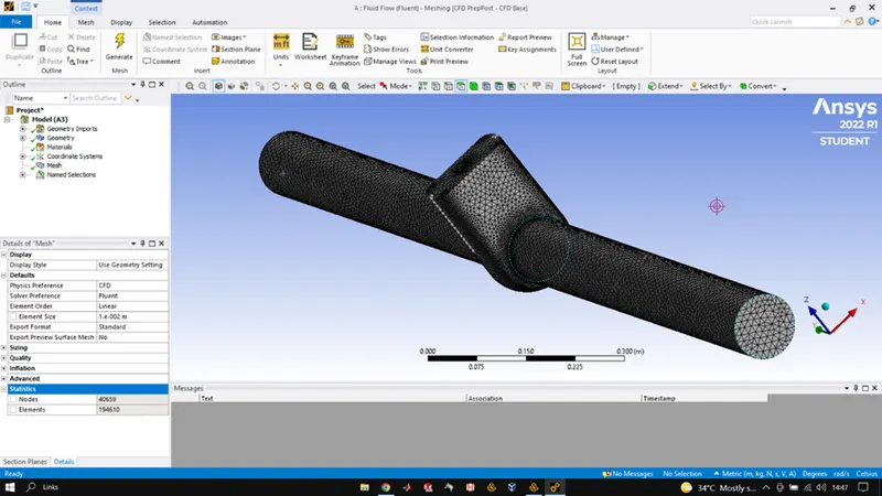
Once fluid volume is extracted, we use the meshing tool to mesh the volume and create the mesh. The size for the mesh element is 10mm and after meshing we name our inlets and outlets.
FLUENT/SETUP
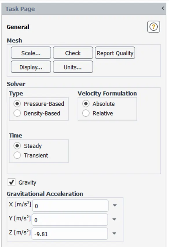
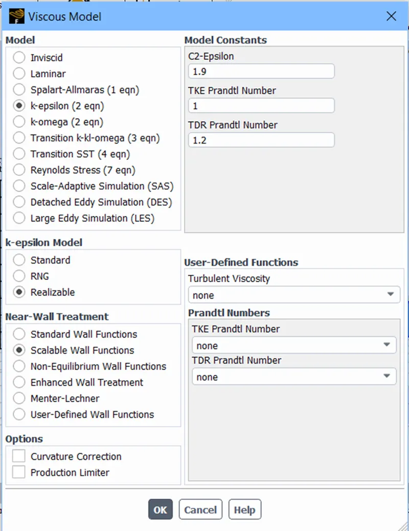
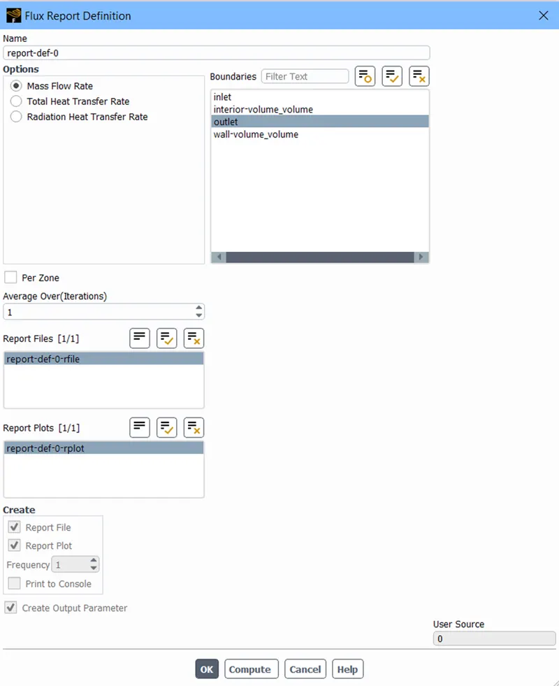
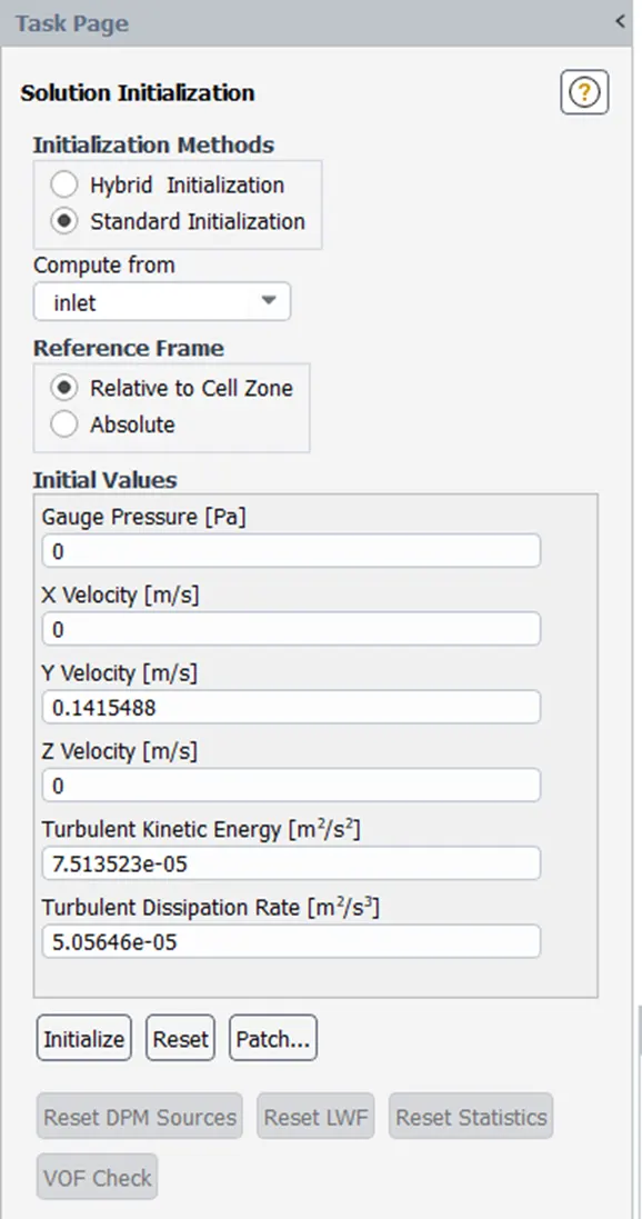
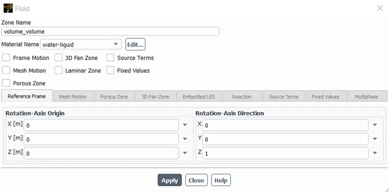
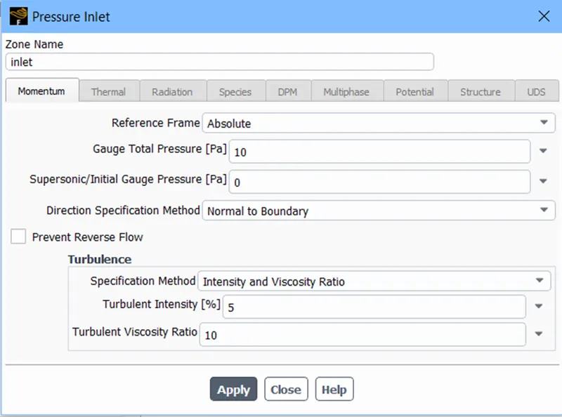
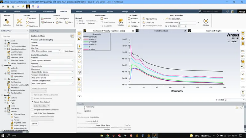
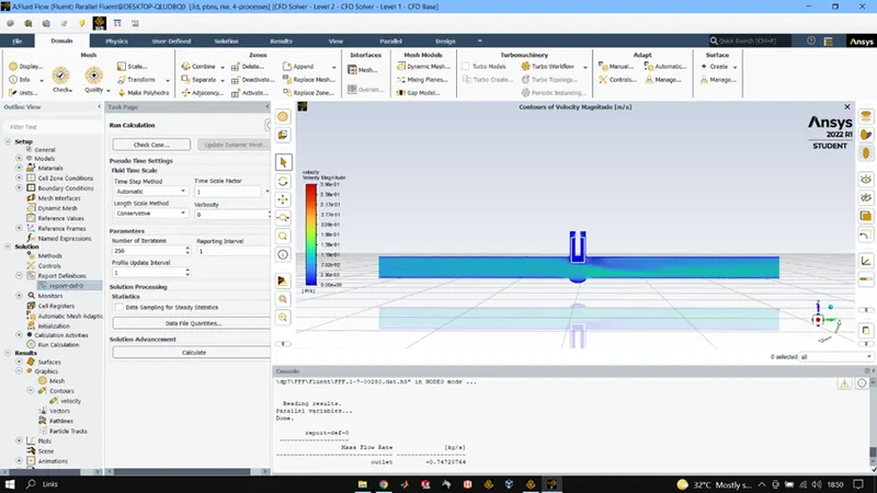
After completing meshing, we come to fluent setup where we use steady state transition and enable gravity and give the acceleration value to the z axis as it is the one representing the direction of gravity. After that K-epsilon realizable scalable wall function viscous model is selected. Then we use the definition tool to plot mass flow rate (present in flux report) make sure create output parameter is checked. We add water material and make sure that the cell zone for volume is water after that for inlet we set BC as pressure inlet and use 10P as the gauge pressure at inlet. After all this we initialize the system by standard method from inlet and then run the simulation for 250 iterations.
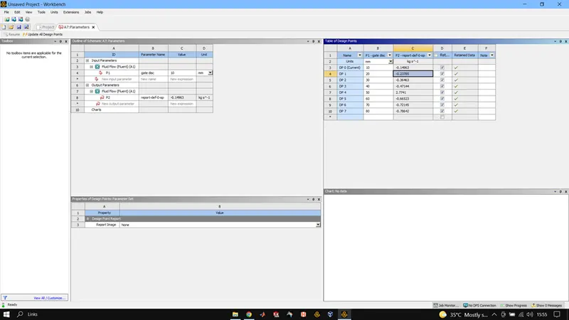
After that we give values for our parameters in the parameter section and update the result for all the design points.
RESULTS:
10MM OPENING
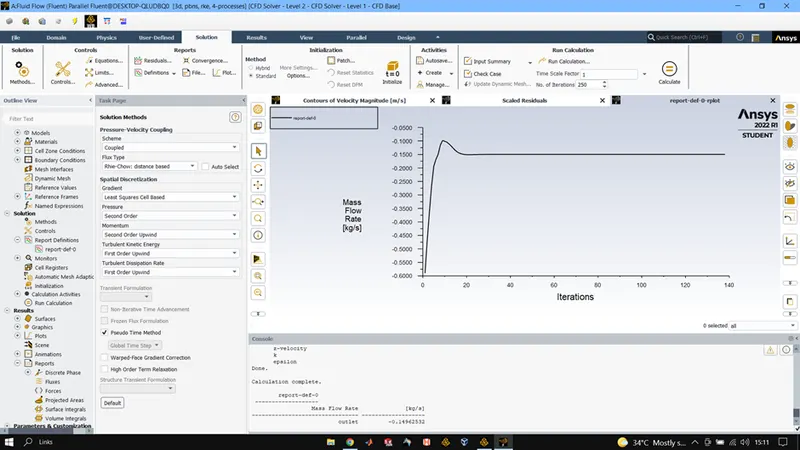
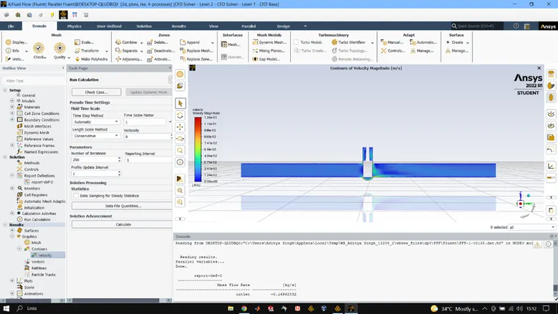
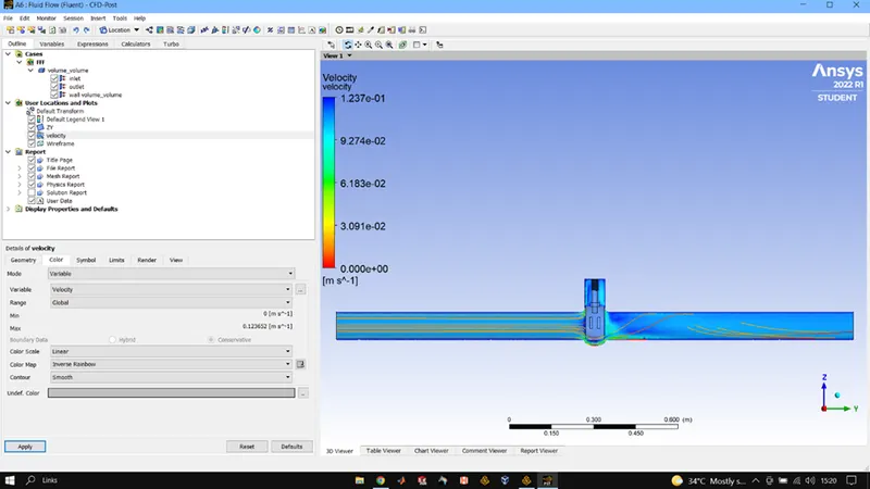
20 MM OPENING
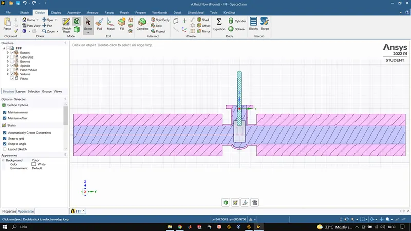
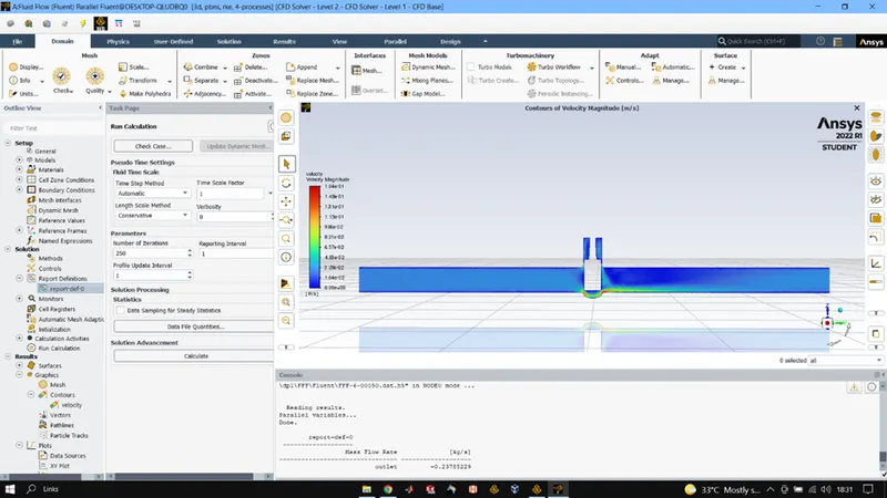
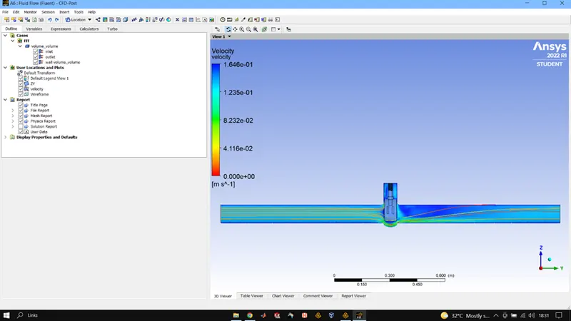
30 MM OPENING
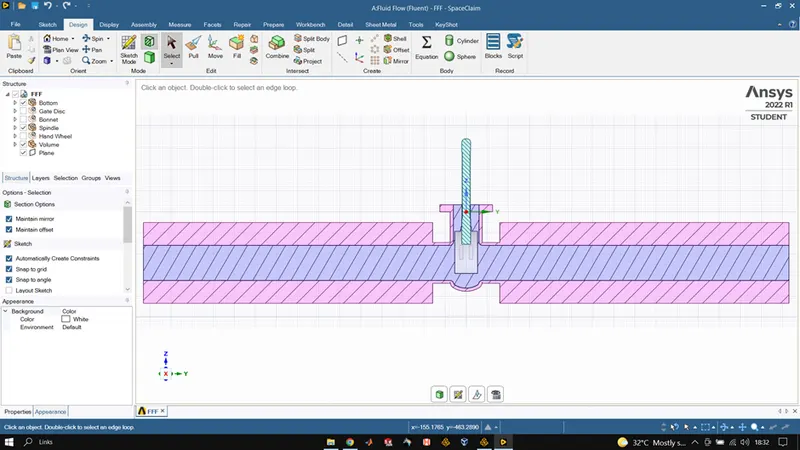
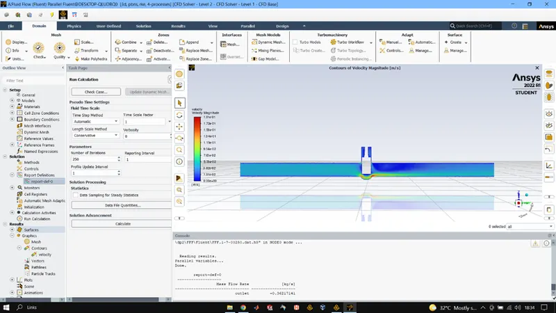
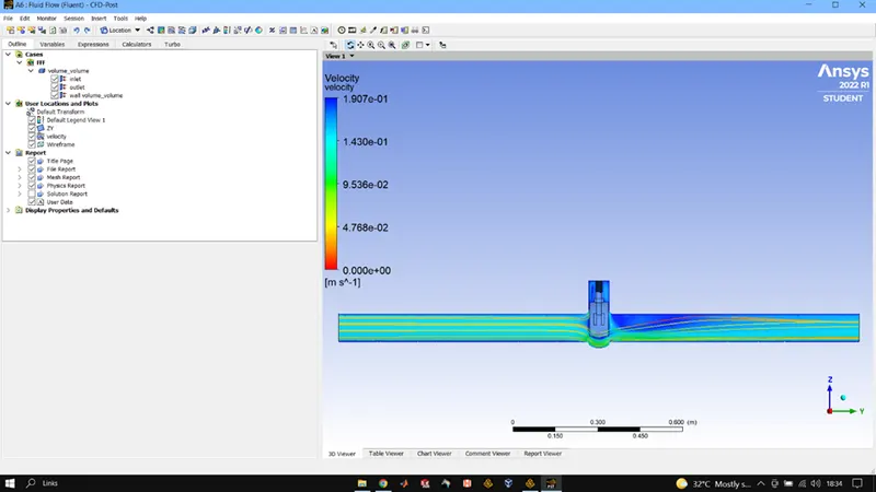
40 MM OPENING
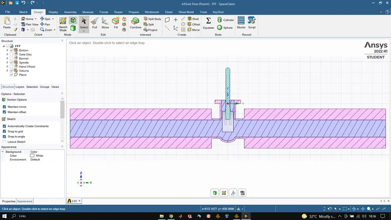
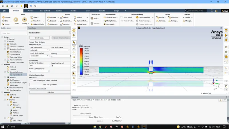
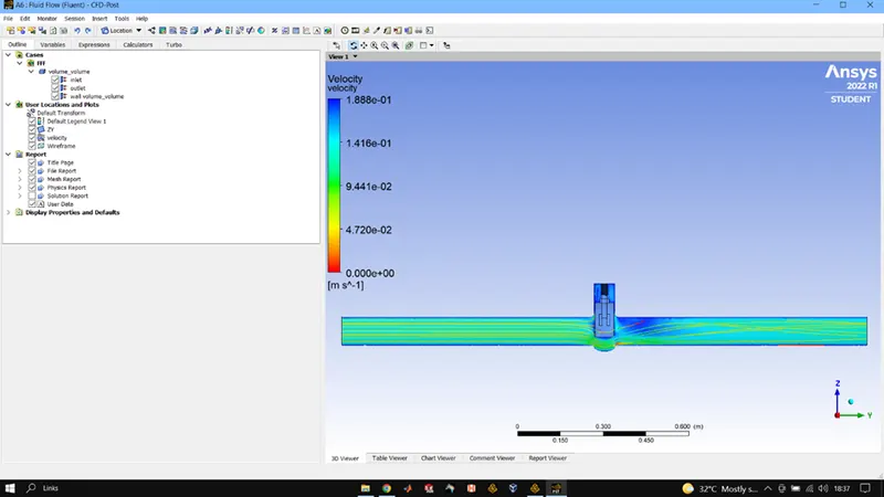
50 MM OPENING
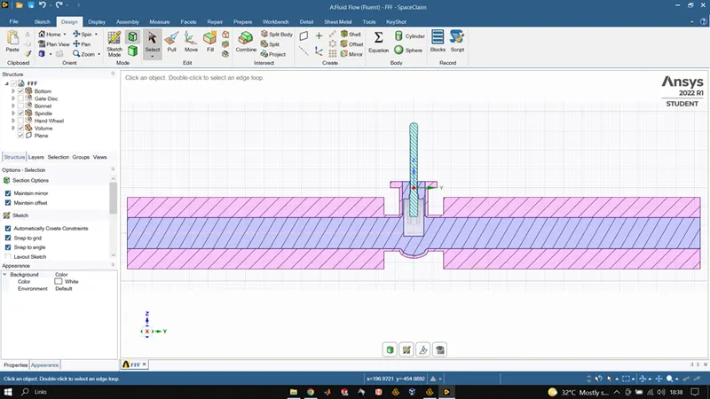
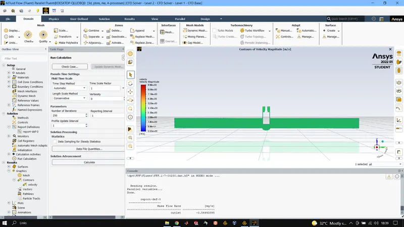
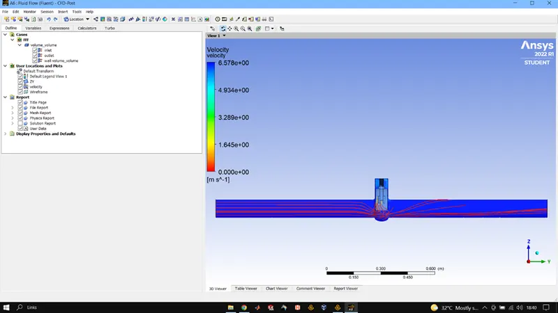
60MM OPENING
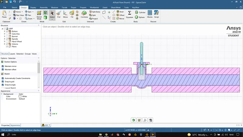
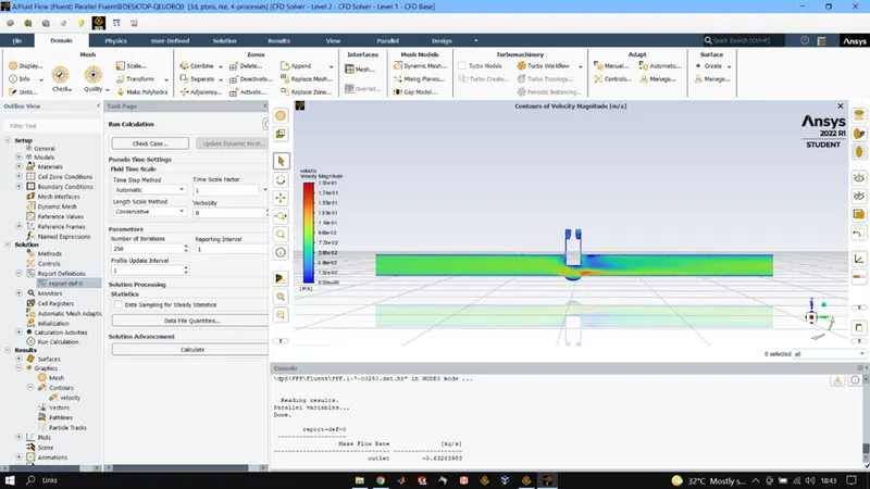
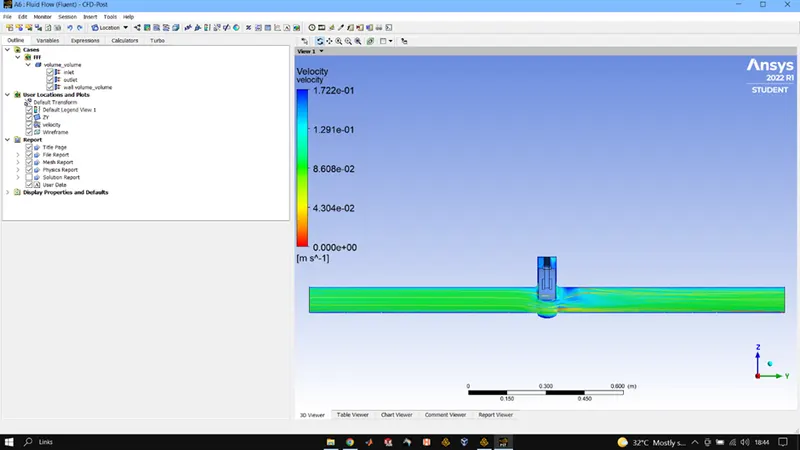
70 MM OPENING
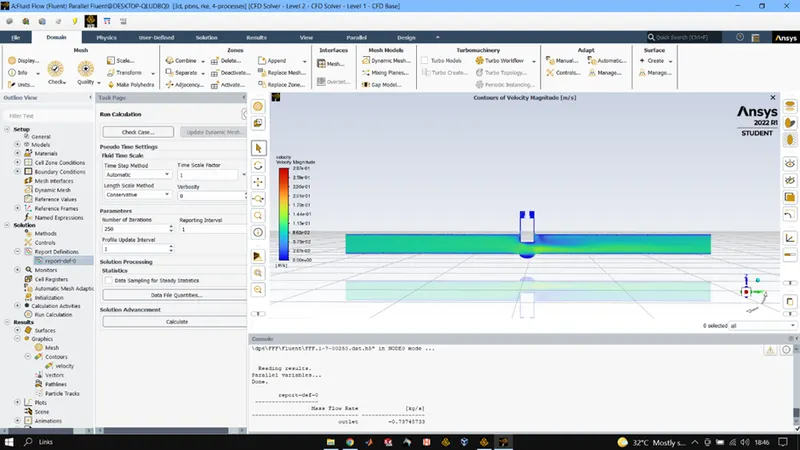
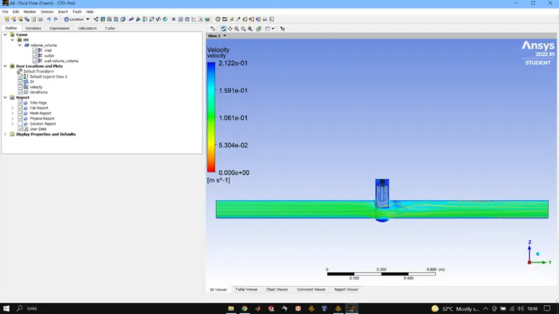
80MM OPENING
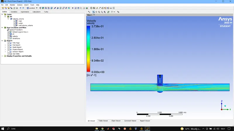
CONCLUSIONS:
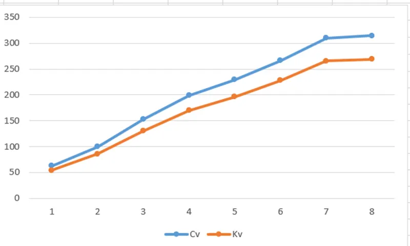
As lift increases of the gate disc the mass flow rate also increases.
With flow rate we can compute the efficiency of the system and effect of pressure on the system. Hence plays an important role in valve selection.
|
CASE |
LIFT |
MASS FLOW RATE |
Cv |
Kv |
|
CASE1 |
10 |
-0.1496 |
62.90 |
53.85 |
|
CASE2 |
20 |
-0.2378 |
100 |
85.60 |
|
CASE3 |
30 |
-0.3621 |
152.27 |
130.35 |
|
CASE4 |
40 |
-0.4721 |
198.53 |
169.95 |
|
CASE5 |
50 |
-0.5444 |
228.94 |
195.98 |
|
CASE6 |
60 |
-0.6326 |
266.03 |
227.73 |
|
CASE7 |
70 |
-0.7374 |
310.11 |
265.46 |
|
CASE8 |
80 |
-0.7472 |
314.24 |
268.99 |