Week 9 - Parametric study on Gate valve.
Aim --> Parametric study on a gate valve using Ansys Fluent.
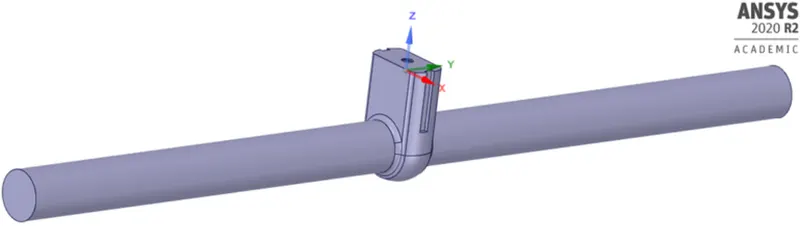
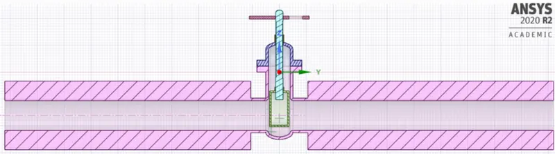
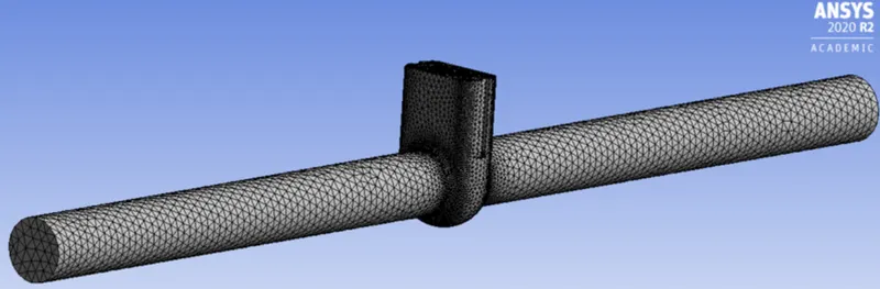
Geometry and Mesh

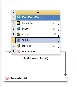
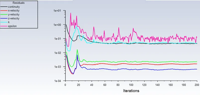
Case setup
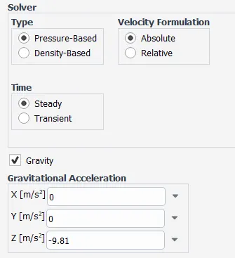
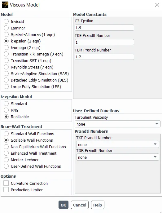
Turbulence model (K-e relizable with scalable wall functions)
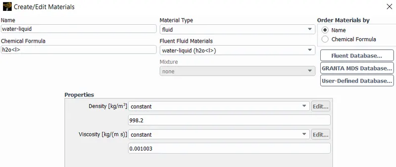
Fluid material --> water-liquid
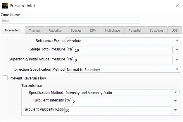
Inlet boundary condition
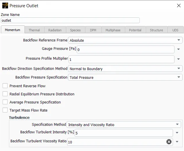
Outlet boundary condition
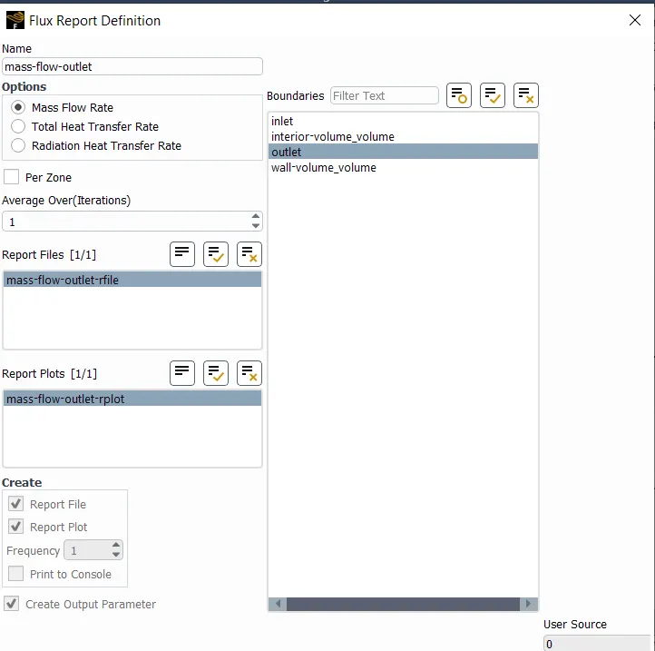
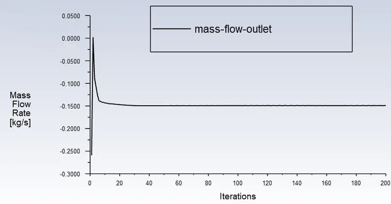
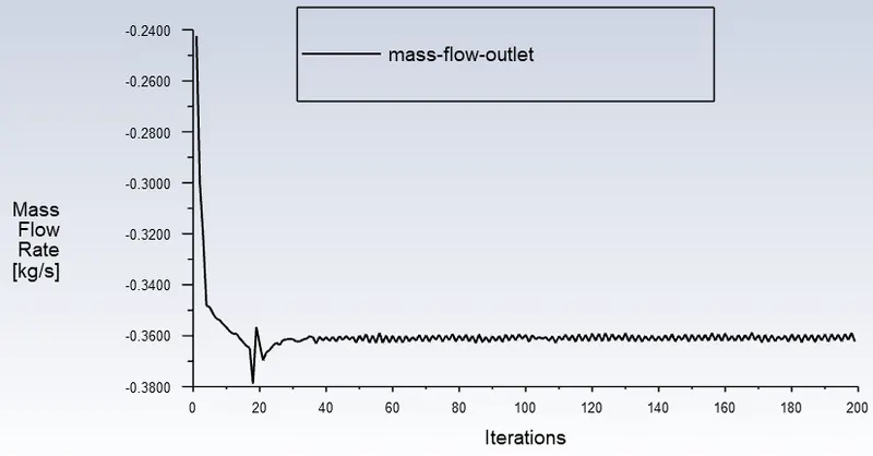
mass flow rate report defination
Solution Initialization
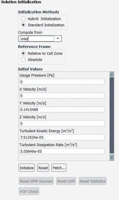
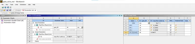
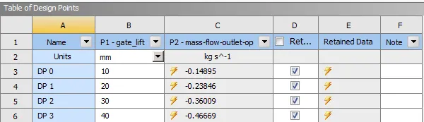
Table of Design points
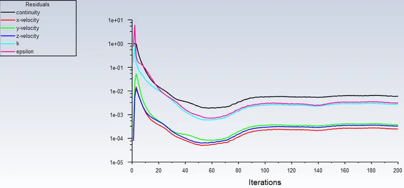
Results
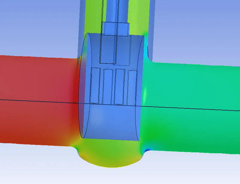
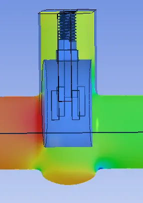
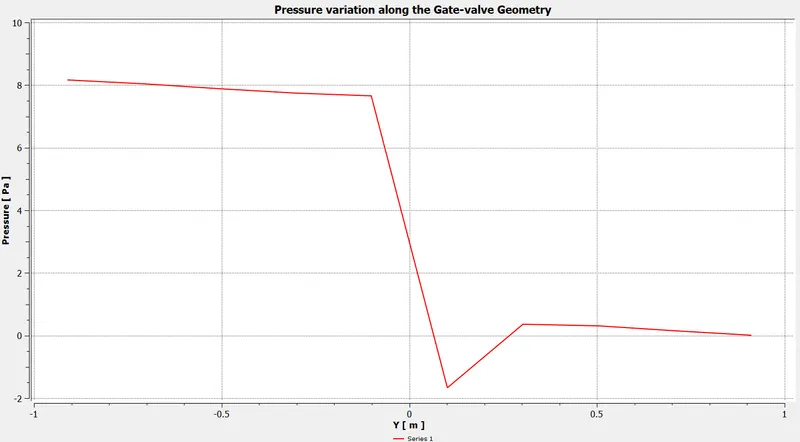
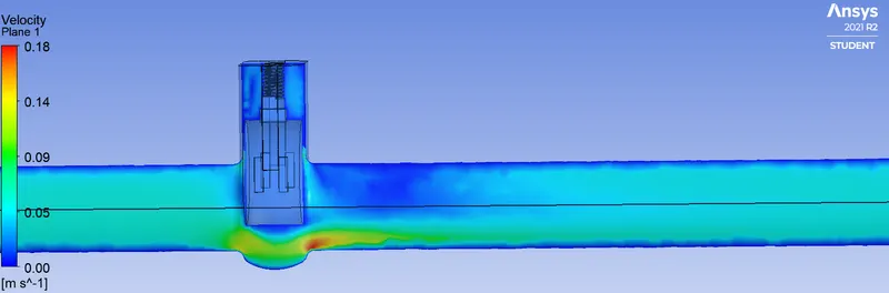
1. DP0 (valve disc lift = 10 mm.)
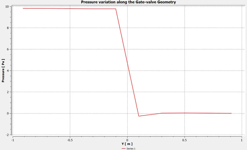
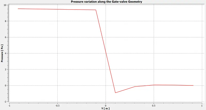
pressure variation across the gate valve disc
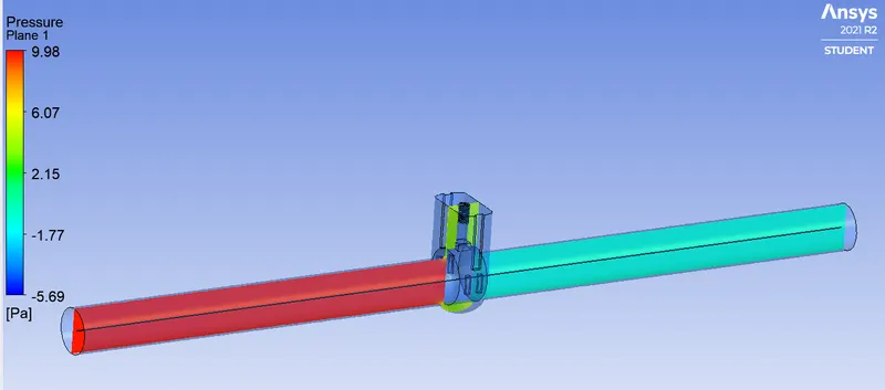
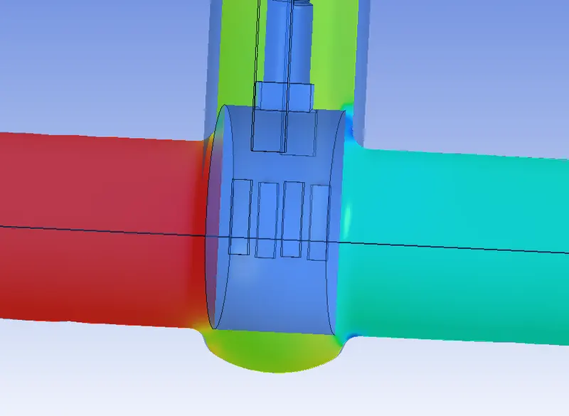
Line plot
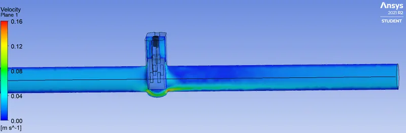
Velocity plot
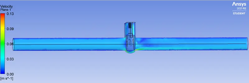
2. DP1 (valve disc lift = 20 mm.)
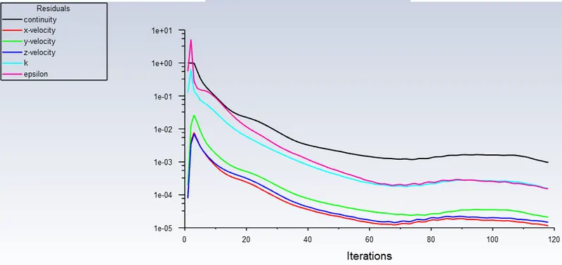
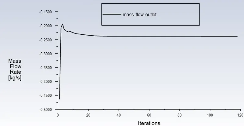
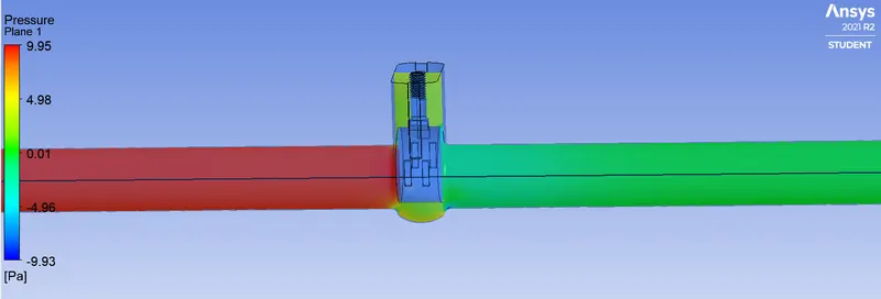
3. DP2 (valve disc lift = 30 mm.)
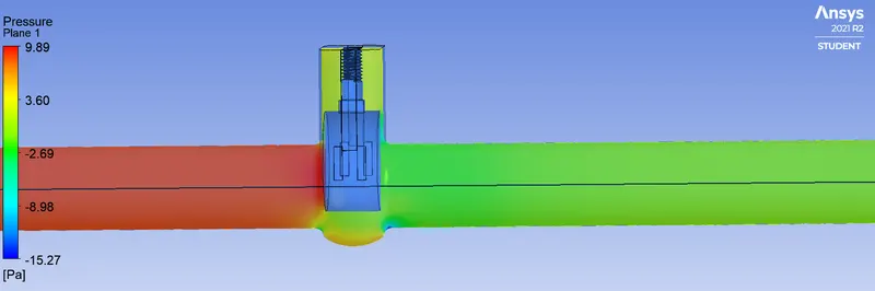
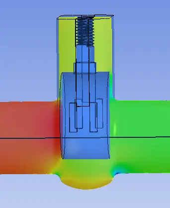
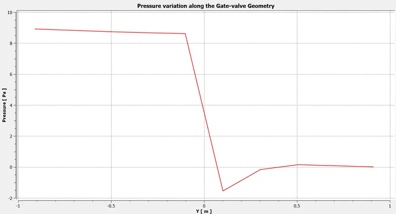
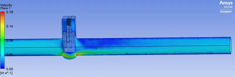
4. DP3 (valve disc lift = 40 mm.)
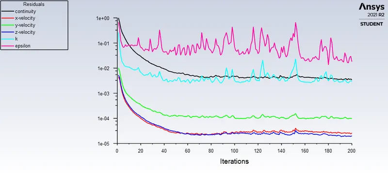
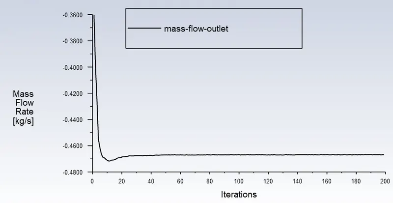
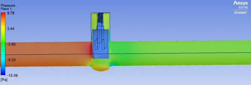
Flow Coefficient
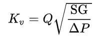
The flow coefficient of a device is a relative measure of its efficiency at allowing fluid flow. It describes the relationship between the pressure drop across an orifice valve or other assembly and the corresponding flow rate.
Mathematically the flow coefficient Cv (or flow-capacity rating of valve) can be expressed as :
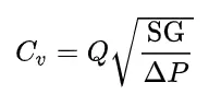
where:
- Q is the rate of flow (expressed in US gallons per minute),
- SG is the specific gravity of the fluid (for water = 1),
- ΔP is the pressure drop across the valve (expressed in psi).
In more practical terms, the flow coefficient Cv is the volume (in US gallons) of water at 60 °F that will flow per minute through a valve with a pressure drop of 1 psi across the valve.
The use of the flow coefficient offers a standard method of comparing valve capacities and sizing valves for specific applications that is widely accepted by industry. The general definition of the flow coefficient can be expanded into equations modeling the flow of liquids, gases and steam using the discharge coefficient.
Flow Factor
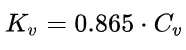
The metric equivalent flow factor (Kv; commonly used everywhere else in the world with the exception of the United States) is calculated using metric units :