Week 9 - Parametric study on Gate valve.
Parametric study on Gate valve
For this challenge, you will have to perform a parametric study on the gate valve simulation by setting the opening from 10 % to 80%.
- Obtain the mass flow rates at the outlet for each design point.
- Calculate the flow coefficient and flow factor for each opening and plot the graph.
- Discuss the results of the mass flow rate and flow coefficient.
-----------------------------------------------------------------------------------------------------------------------------------------------------------
Theory-
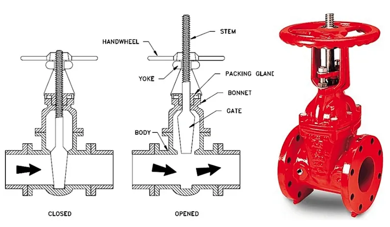
Gate valves are machine elements that are commonly used to control the flow of fluids as gate valve provides a positive sealing at high pressure of liquids & gases.
Flow coefficient-
The flow coefficient of a device is a relative measure of its efficiency at allowing fluid flow. It describes the relationship between the pressure drop across an orifice valve or other assembly and the corresponding flow rate.
Mathematically the flow coefficient Cv (or flow-capacity rating of valve) can be expressed as :
- C v = Q SG Δ P {\displaystyle C_{v}=Q{\sqrt {\dfrac {\text{SG}}{\Delta P}}}}

where:
- Q is the rate of flow (expressed in US gallons per minute),
- SG is the specific gravity of the fluid (for water = 1),
- ΔP is the pressure drop across the valve (expressed in psi).
Flow factor-
The metric equivalent flow factor (Kv; commonly used everywhere else in the world with the exception of the United States) is calculated using metric units :
- K v = Q SG Δ P {\displaystyle K_{v}=Q{\sqrt {\dfrac {\text{SG}}{\Delta P}}}}

where
- Kv is the flow factor (expressed in [ m 3 . h − 1 . b a r − 0.5 ] {\displaystyle [m^{3}.h^{-1}.bar^{-0.5}]}
 ).
). - Q is the flowrate (expressed in cubic metres per hour [ m 3 / h {\displaystyle m^{3}/h}
 ]),
]), - SG is the specific gravity of the fluid (for water = 1),
- ∆P is the differential pressure across the device (expressed in [bar]).
Kv can be calculated from Cv using the equation:
- K v = 0.865 ⋅ C v {\displaystyle K_{v}=0.865\cdot C_{v}}

-----------------------------------------------------------------------------------------------------------------------------------
Simulation-
Steps in simulation: Open Ansys workbench, drag & drop fluid flow (Fluent) onto project schematic. below are steps we need to follow to solve a particular engineering system from CFD standpoint.
- Geometry: Spaceclaim, it is used for import the geometry & other CAD related functions like geometry clean-up etc.
- Mesh: used to generate mesh & other mesh control option there, also assign name which helps during BCs setup.
- Setup: used to define physics of problem, like BCs, material & type of solving method, iterations ect.
- Solution: where runtime results visualization done.
- Results: CFD-Post, where post processing of results will be done.
CAD setup-
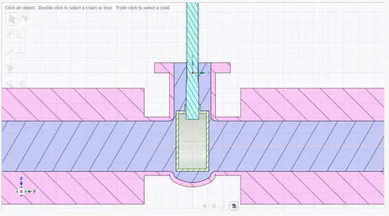
Import gate valve geometry into spaceclaim.
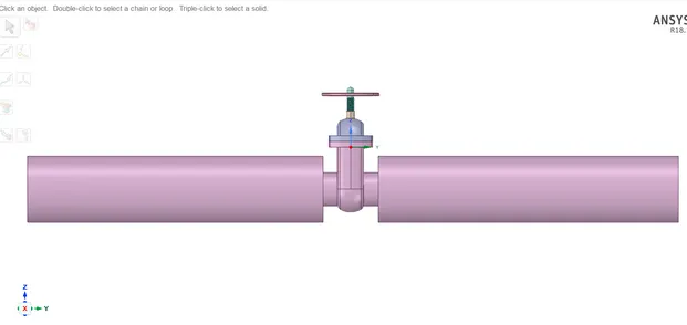
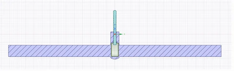
As the imported model is a solid, so we need to carry out an analysis of the fluid volume,hence extract the fluid volume.
Prepare->select volume extract->select edges.
Select front & back edges of the circles (for inlet & outlet).
suppress the geometry except for fluid volume.
Parametrize the lift by clicking on P symbol.
Mesh Generation-
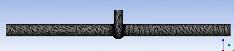
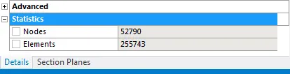
Name selection: inlet for one end & outlet for other end.
Mesh element size is 8 mm.
Fluent setup-
Physics setup-
select k-epsilon, realizable with scalable wall functions.
Pressure based solver.
Steady state solver & enable gravity in z-axis -9.81 m/s^2.
Material Selection:
For liquid- water
density= 998.2 kg/m^3
viscosity= 0.001003 kg/m-s
Boundary conditions:
Inlet type- pressure type
assign gauge pressure 10 Pa, for pipe flow 10 Pa inlet pressure is acceptable.
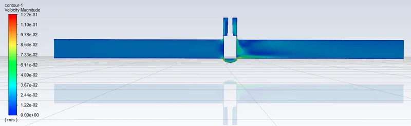
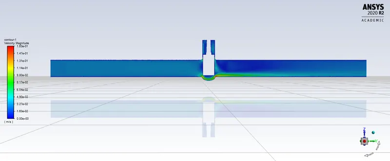
Create a velocity contour.
Assign mass flow rate output parameter for the parametric study.
Case 1:- without parametric study for lift= 10 mm.
plots & results-
Cad setup-
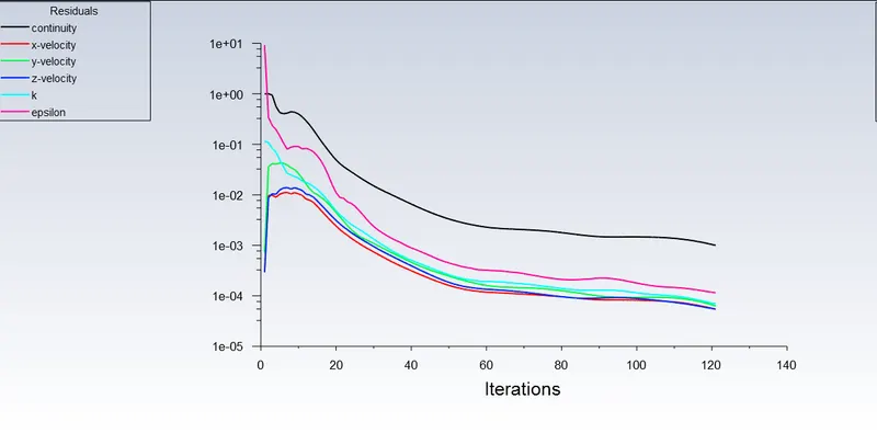
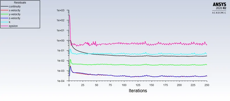
Residuals:
Velocity contour:
Case 2:- with parametric study
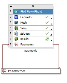
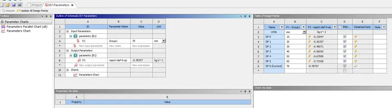
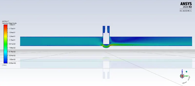
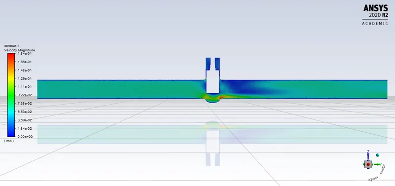
Parametric study is applied to valve lift for 20, 30, 40, 50, 60, 70, & 80 mm.
As earlier lift without study is 10 mm, so this earlier lift is already added to the above valve lift.
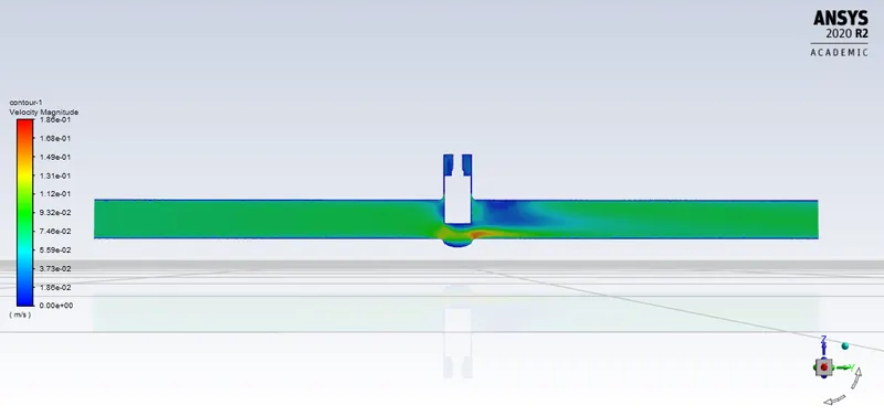
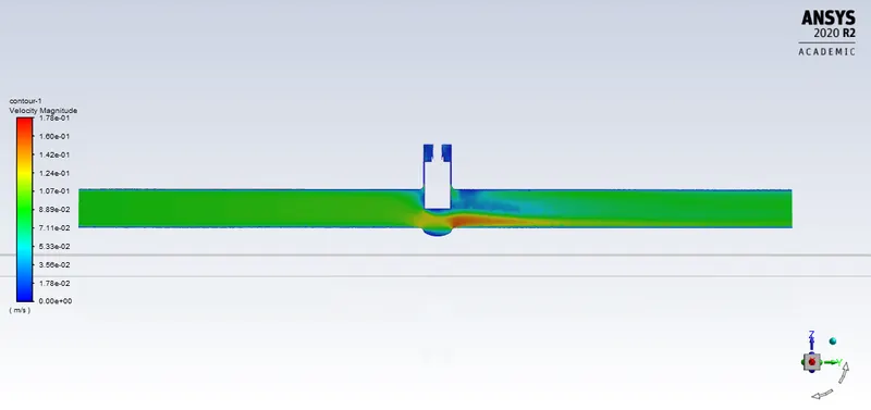
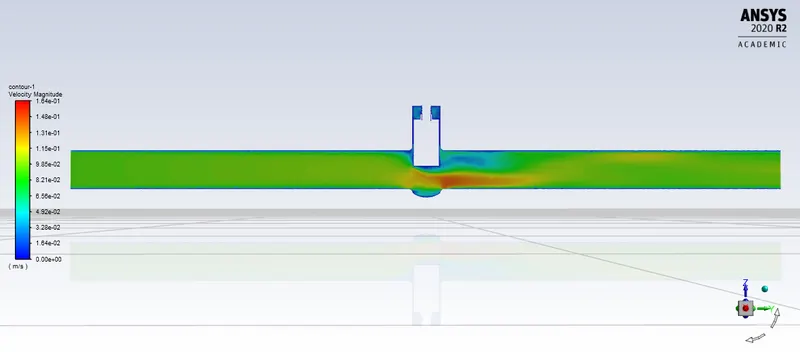
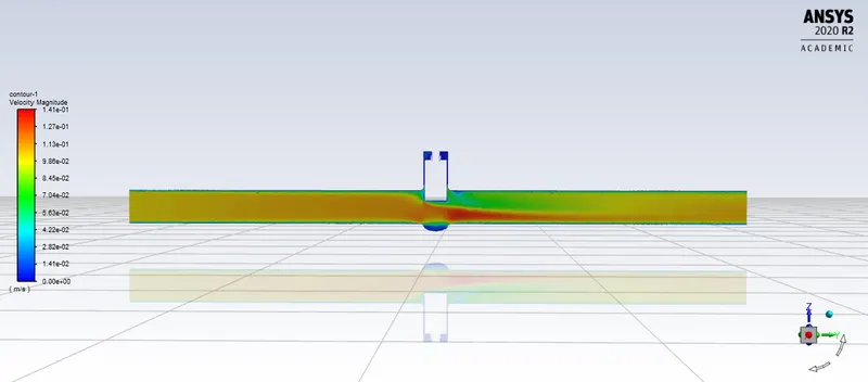
Plots & results for valve lift= 20, 30, 40, 50, 60, 70, 80 mm respectively.
Cad setup-
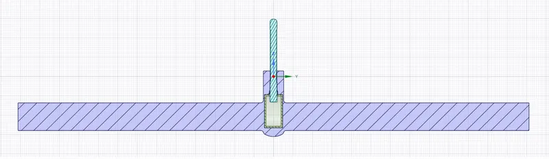
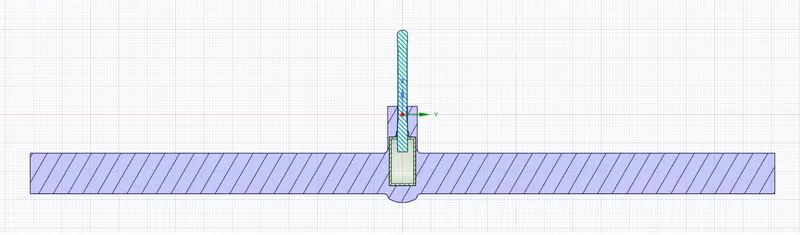
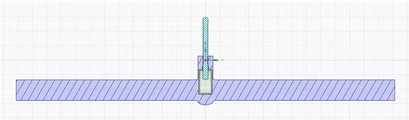
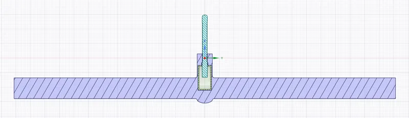
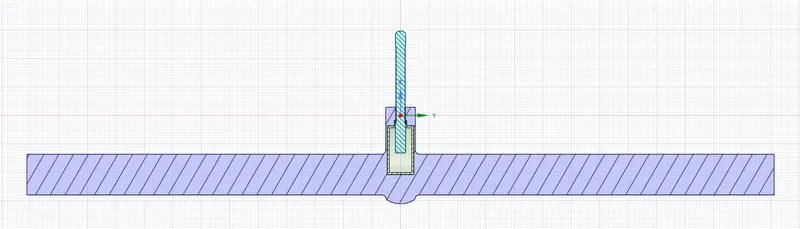
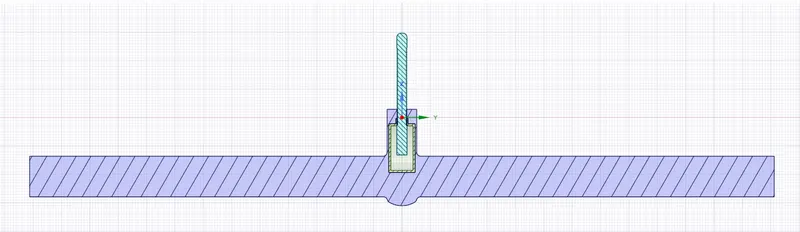
During 80mm lift case, we also move spindle 10mm up for proper sealing & fluid does not go inside gate disc space.
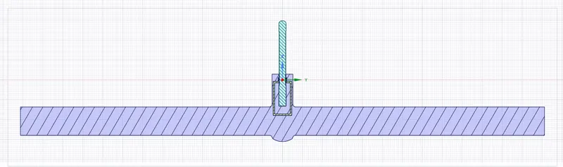
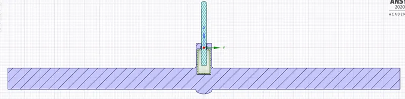
without spindle 10mm up, fluid goes inside date disc space, as shown above. with spindle 10 mm up, no fluid inside gate disc space.
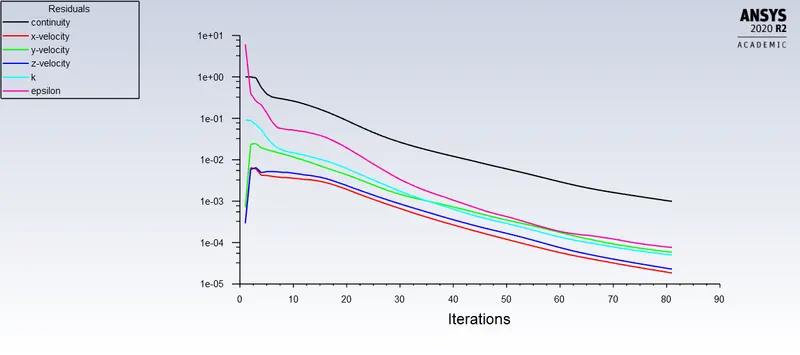
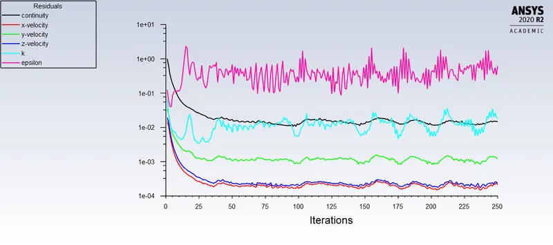
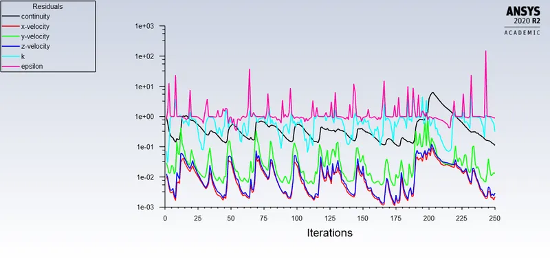
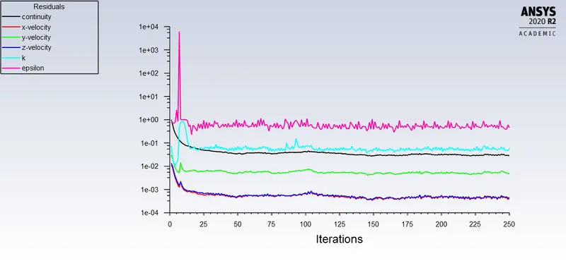
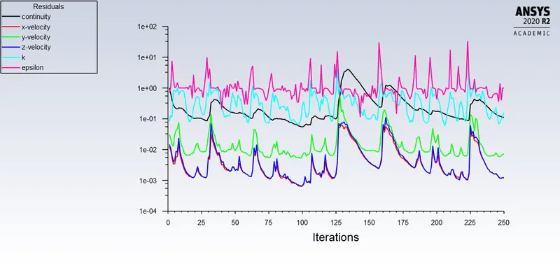
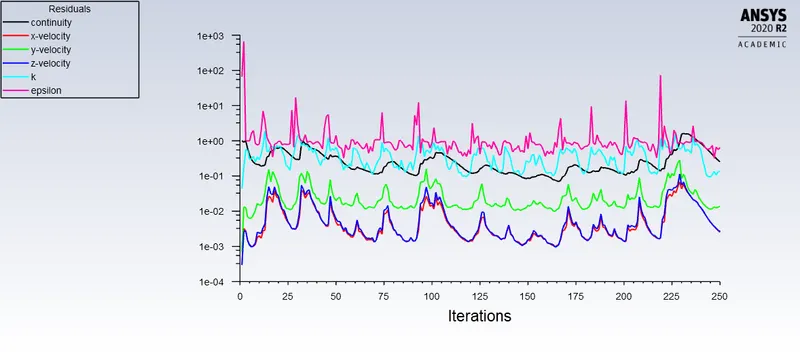
Residuals-
Velocity contour-
Calculation the flow coefficient & flow factor for each openings:
flow coefficient (Cv):

For 10,20,30,40,50,60,70 & 80 mm valve lift-
Cv= 3.6*0.1489* √(1/10^(-4) ) = 53.604
Cv= 86.22
Cv= 130.896
Cv= 165.852
Cv= 203.544
Cv= 244.656
Cv= 257.508
Cv= 283.536
Flow Factor(Kv):
For 10,20,30,40,50,60,70 & 80 mm valve lift-
Kv= 46.367
Kv= 74.580
Kv= 113.225
Kv= 143.462
Kv= 176.066
Kv= 211.627
Kv= 222.744
Kv= 245.259
Effect of valve lift on mass flow rate, flow coefficient (Cv) & flow factor (Kv)-
| Valve Lift (mm) | 10 | 20 | 30 | 40 | 50 | 60 | 70 | 80 |
| Mass flow rate (kg/s) |
-0.1489 |
-0.2395 | -0.3636 | -0.4607 | -0.5654 | -0.6796 | -0.7153 | -0.7876 |
| Flow coefficient (Cv) | 53.604 | 86.22 | 130.896 | 165.852 | 203.544 | 244.656 | 257.508 | 283.536 |
| Flow factor (Kv) | 46.367 | 74.580 | 113.225 | 143.462 | 176.066 | 211.627 | 222.744 | 245.259 |
Conclusion-
- As valve lift increases, mass flow rate, flow coefficient & flow factor also increased.
- The negative value of the mass flow rate indicates the mass is flowing out of the valve.
- Simulation time can be reduced by using parametric study.
- The use of flow coefficient offers a standard method of comparing valve capacities, to determine the inlet pressure & sizing valves for specific applications.