Week 9 - Mini project - Flow over an Airfoil
Objective:
Simulate flow over a 4 digit airfoil i.e NACA 2412 Airfoil.
Visit the site to get .DAT file for NACA 2412 Airfoil,
http://airfoiltools.com/airfoil/naca4digit
You will have to calculate the following,
- Drag co-efficient Vs Angle of Attack
- Lift co-efficient vs Angle of Attack
- Compare the effect of turbulence models on the above two results.
- Make sure that the inlet Reynolds number is 200,000
- Make sure you do above calculations for the following angle of attacks,
- Angle of attack = 1º
- Angle of attack = 5º
- Angle of attack = 10º
- Angle of attack = 15º
NOTE:
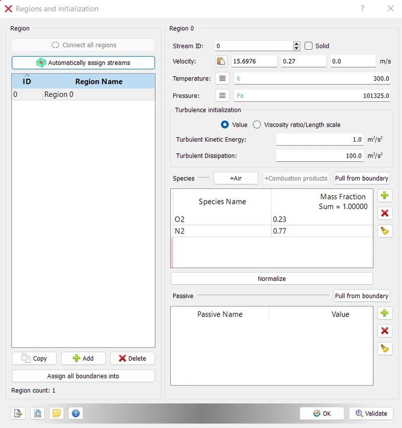
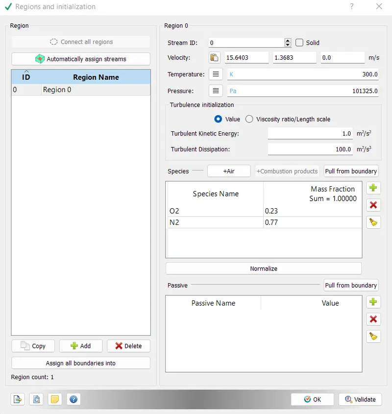
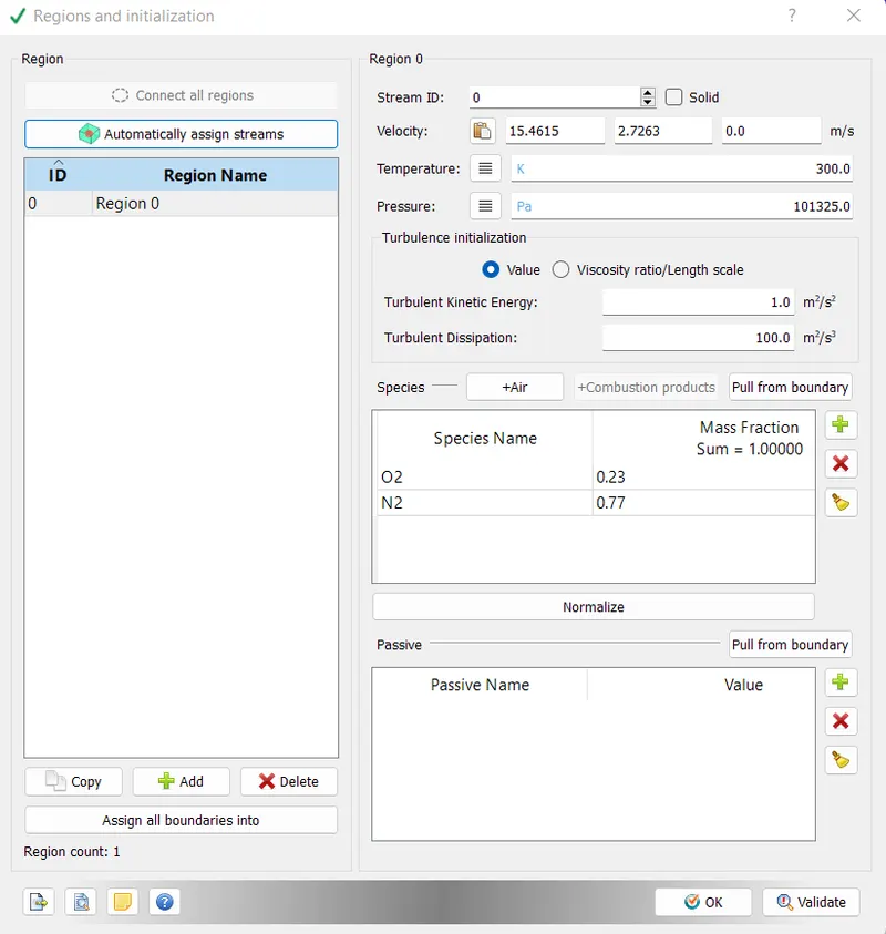
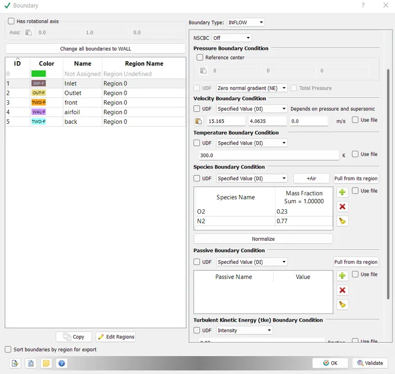
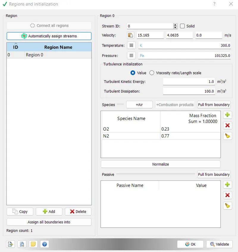
In regions and initilization, value of velocity should be same as that of Inlet velocity.
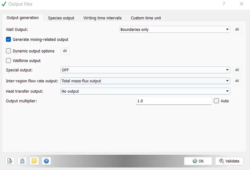
Also, while setting up the case, make sure, wall output (BOUNDARIES ONLY) is enabled as this will dump wall averaged output data which is very much important for any external aerodynamic simulations.
This can be done by going into OUTPUT FILES under OUTPUT/POST PROCESSING in the case setup tree.
Answer:
The airfoil has been created in the Solidworks. The coordinates were taken from the website mentioned in the objective. The extra column of zeros (0) was added into the cordinate file to represent the z-axis because in Solidworks, the coordinates of the curve has only been accepted in three dimensional format only. The command called Curve Through XYZ points was used.
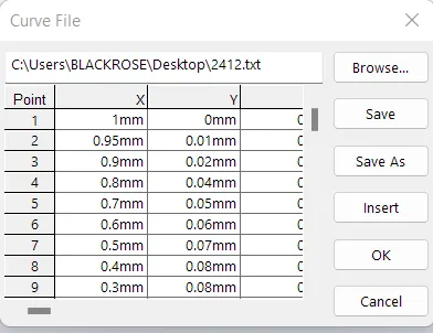
The generated curve through above points was first converted into 3d sketch by projecting the curves. The projected curve was closed to make it close area to convert it into surface. This surface was imported into Converge CFD in STL format.
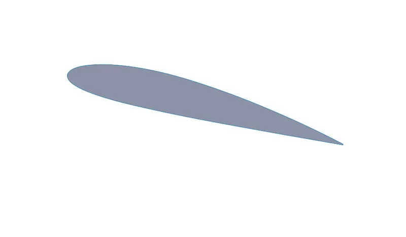
After importing into Converge CFD.
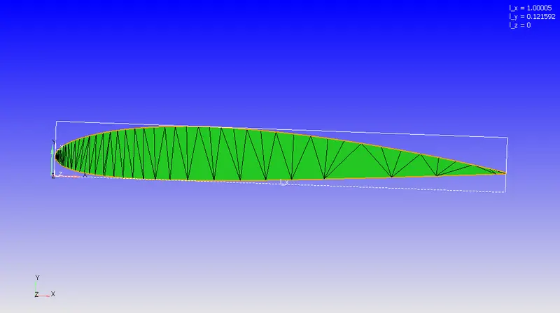
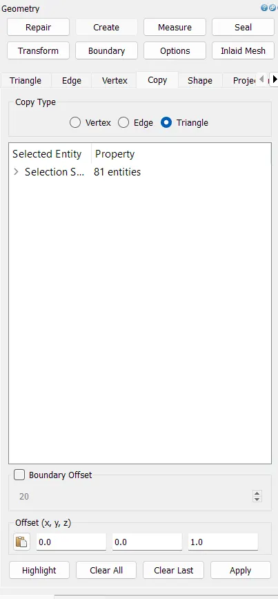
Copying the surface at following location
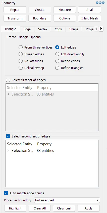
Connecting both surfaces through loft edges command
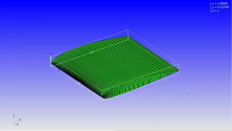
Generated part
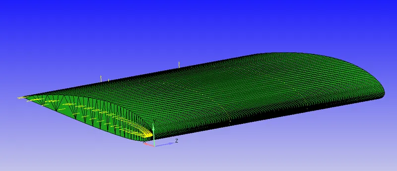
Direction of the normals have been corrected by making them facing inside.
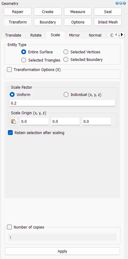
Now to reduce the number of elements, the geometry has been scaled down by factor of 0.2.
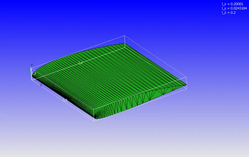
Next, we need to create wind tunnel. The size of the wind tuneel will be 10 times the bounding box length in x- direction.
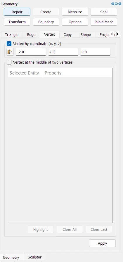
First vertex will be created by entering coordinates which are as follows:
-2m, 2m, 0m
-2m, -2m, 0m
2m, 2m, 0m
2m, -2m, 0m
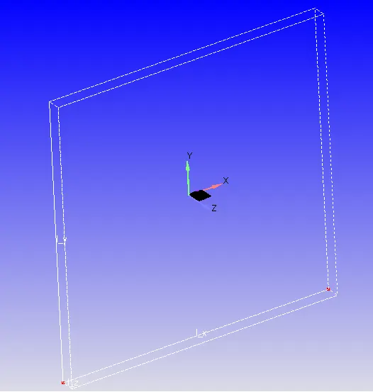
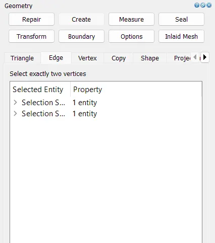
Creating surface by connecting vertexes using the ordered vertex list
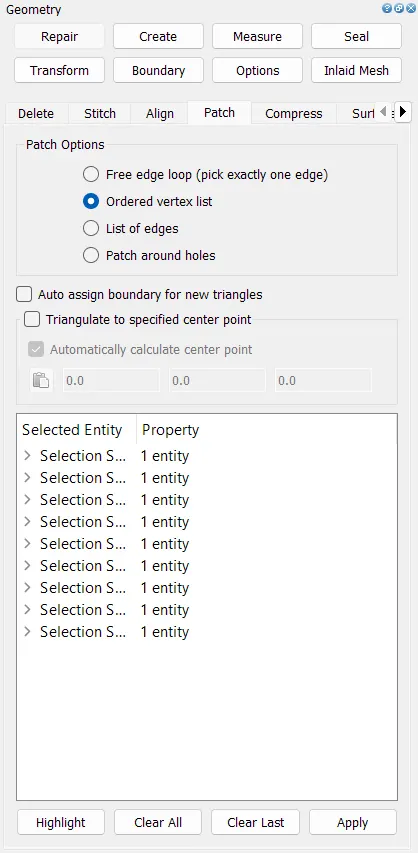
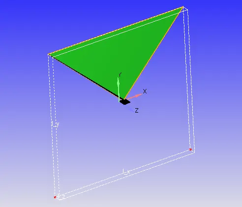
Using create edges option, the edges were created by connecting the vertexes.
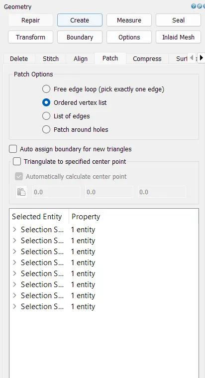
Next, using patch option in repair tab, the surface has been generated as shown below.
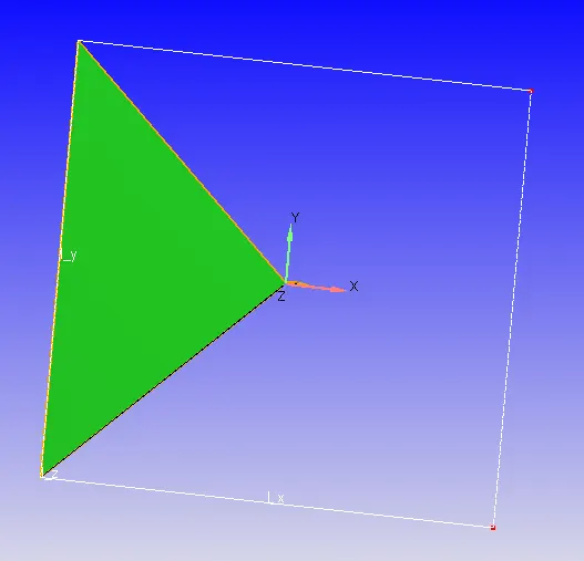
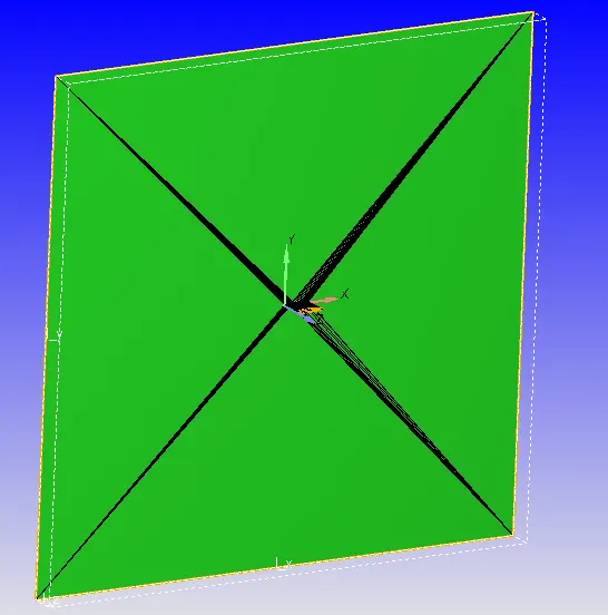
Creating 2D wind tunnel by deleting all the extra surfaces & correcting direction of all normals.
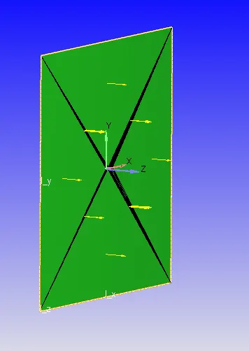
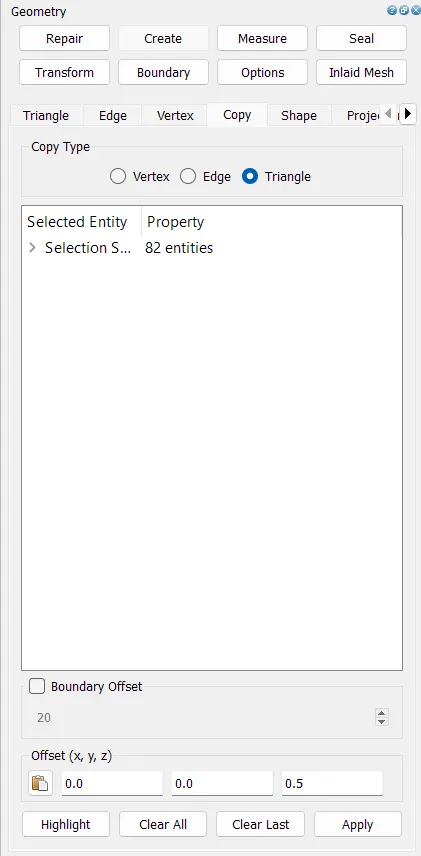
Copying the surface at 0.5m in Z direction to convert it into 3D wind tunnel.
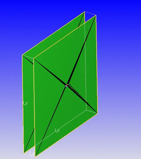
Closing the wind tunnel using loft edges
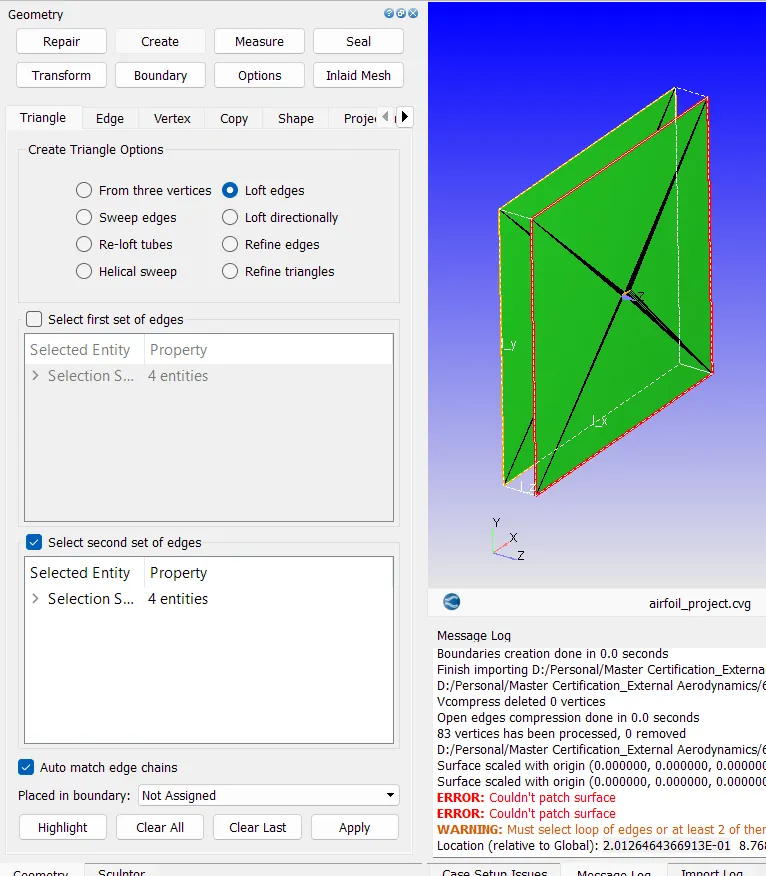
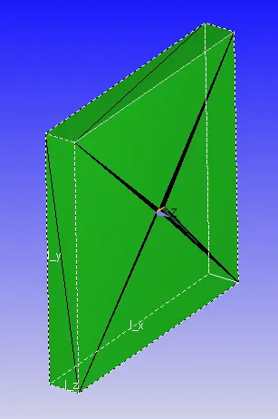
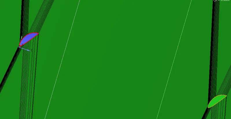
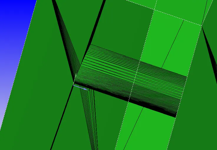
To create the airfoil area into wind tunnel the edges of the airfoil section on both, front & back surfaces, have been connected using loft edges.
Boundaries
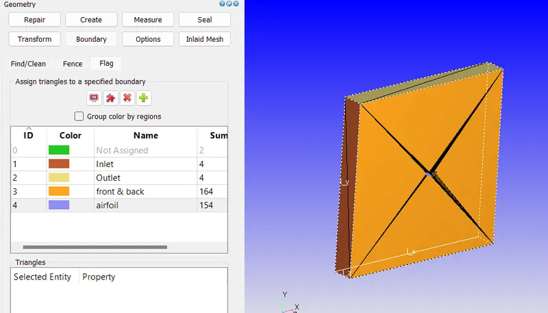
Case Setup
Simulation type
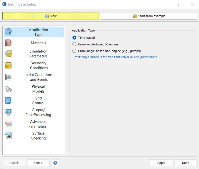
Material
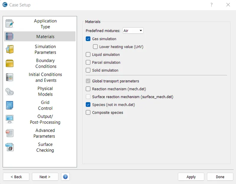
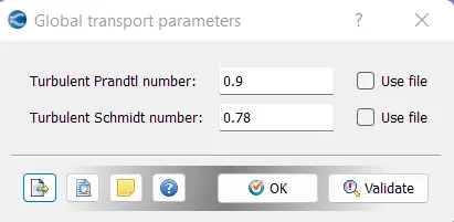
Global Transport Parameters
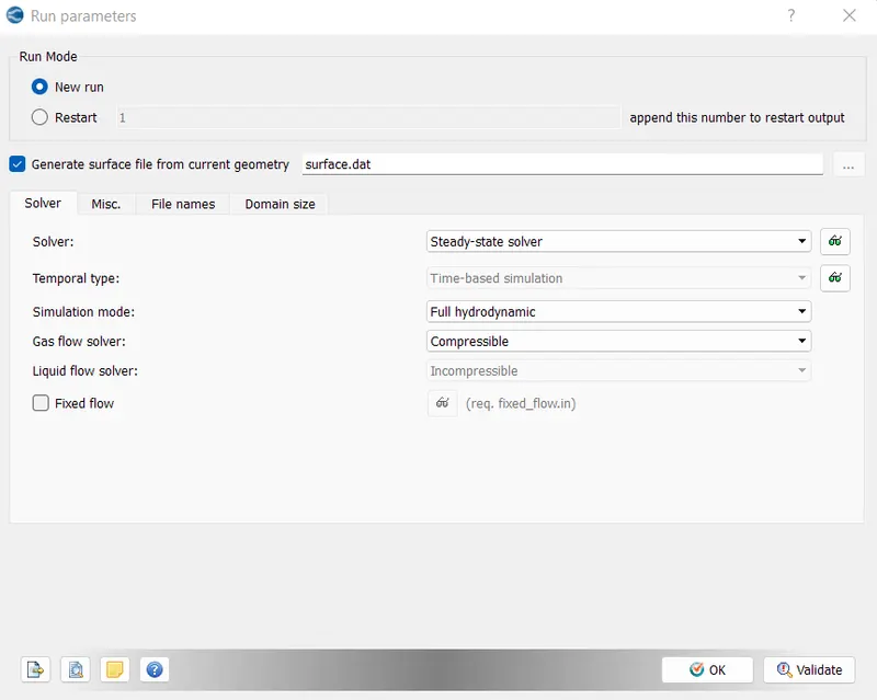
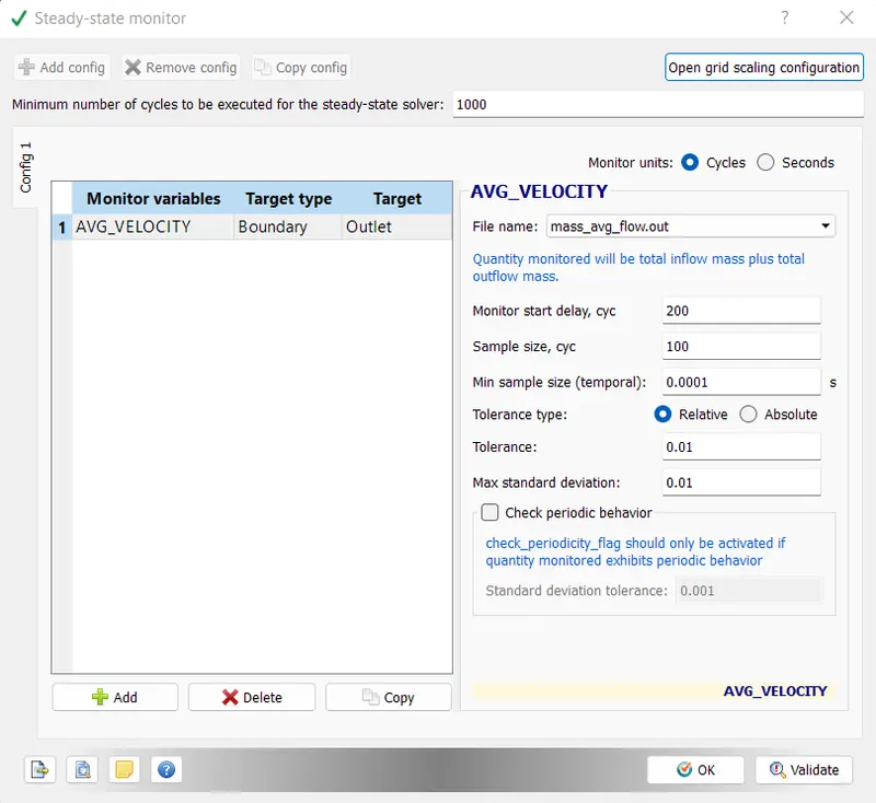
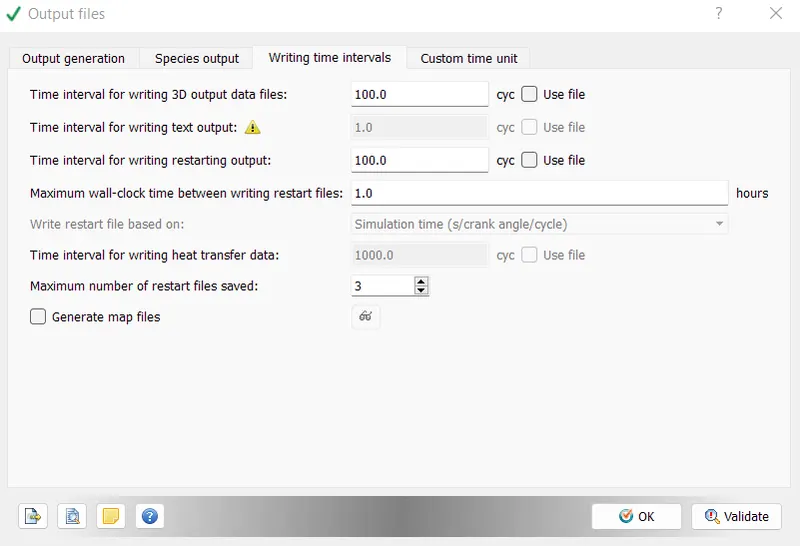
Run Parameters
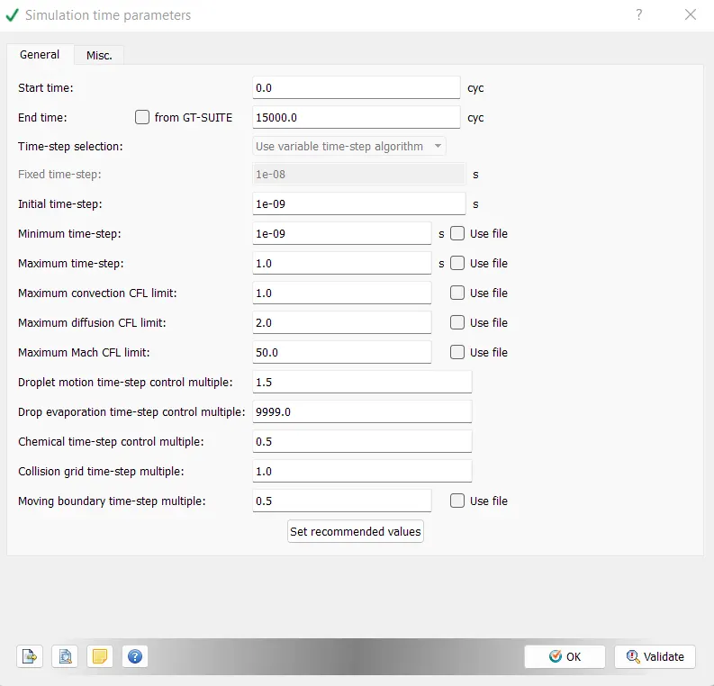
Simulation Time Parameters
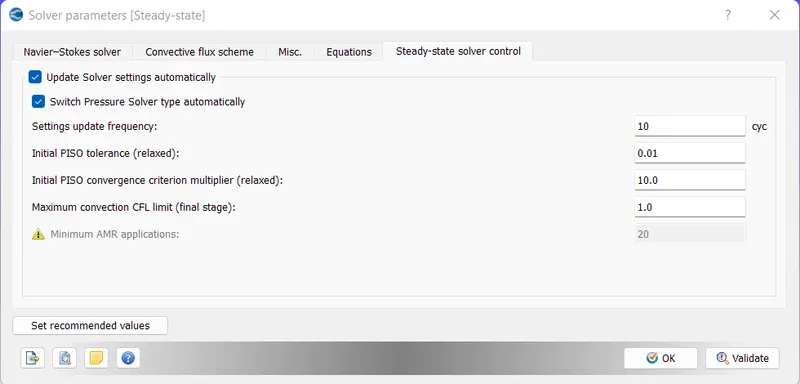
Solver Parameters

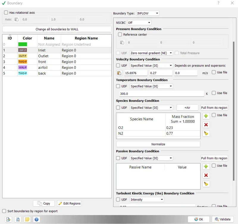
Inlet velocity
For 200000 Reynolds Number
`R_e = (rho*u*L)/mu`
where
rho = 1.184 kg/m^3
L = 0.2m
Re = 200000
mu = 0.0000186 kg/(m.s)
So, u = 15.7 m/s
Following table provides the detail of the inlet velocity for different angle of attack.
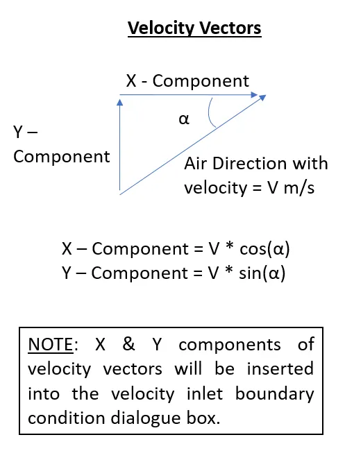
| AOA (degree) | Desired Velocity (m/s) | X - Velocity (m/s) | Y - Velocity (m/s) |
| 1 | 15.7 | 15.6976 | 0.2740 |
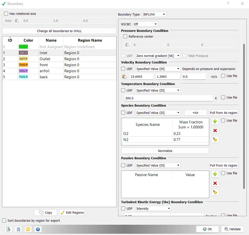
| 5 | 15.7 | 15.6403 | 1.3683 |
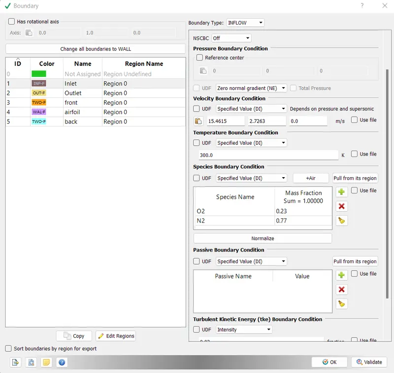
| 10 | 15.7 | 15.4615 | 2.7263 |
| 15 | 15.7 | 15.1650 | 4.0635 |
Setup Procedure of Angle of Attack = 1 degree
Regions & Initialization
x & y velocity for 1 degree angle of attack has been inserted from above table.
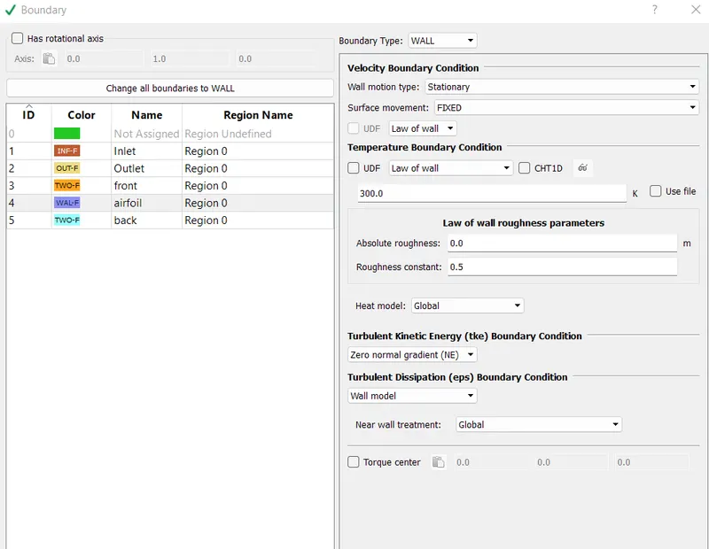
Boundary Conditions
Inlet
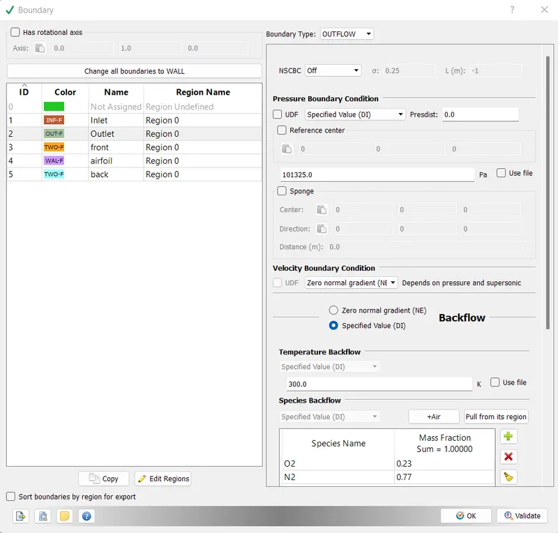
Outlet
Front
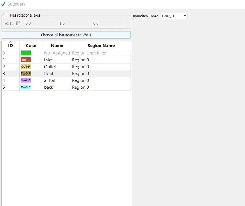
Back
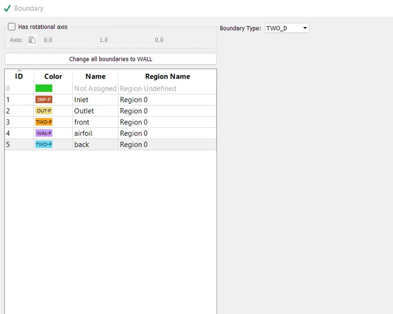
Airfoil
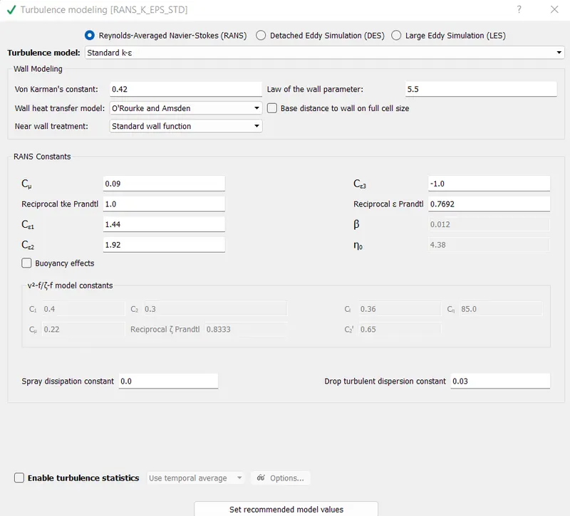
Turbulence Model
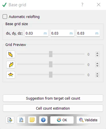
Mesh
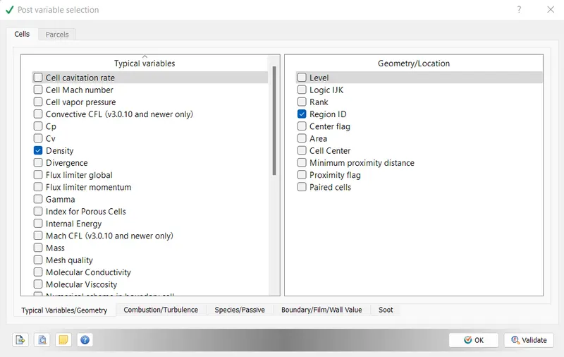
Post Variable
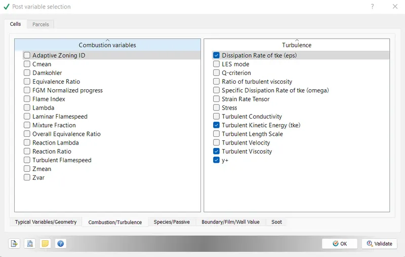
Output Variable
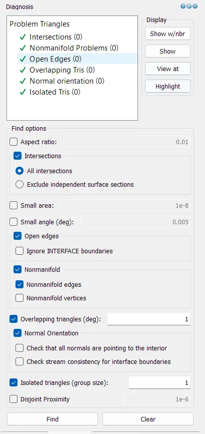
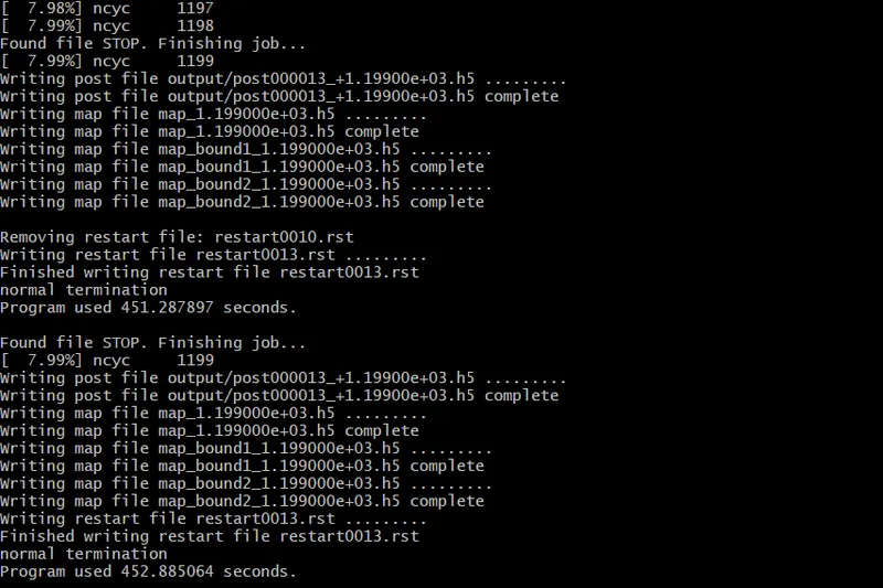
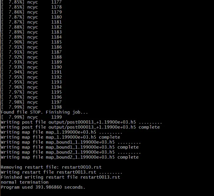
Final Diagnosis
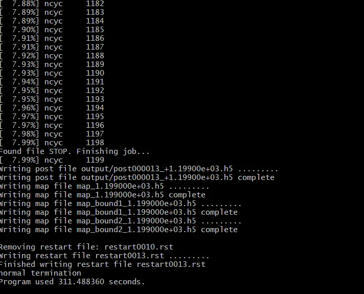
Results
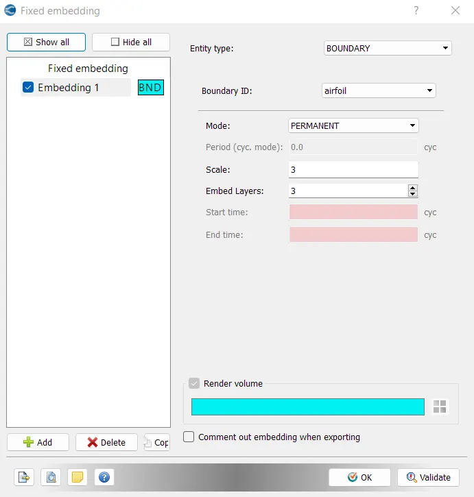
Mesh
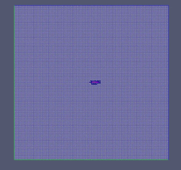
Mesh - Fixed Embedding
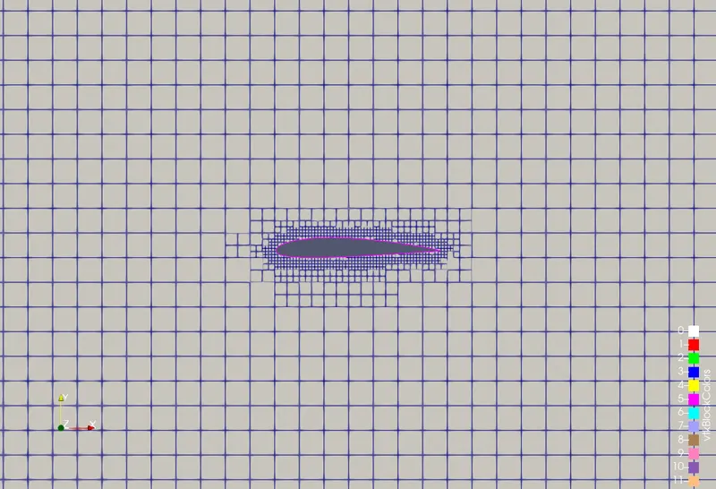
AOA = 5 degree
AOA = 10 degree
AOA = 15 degree
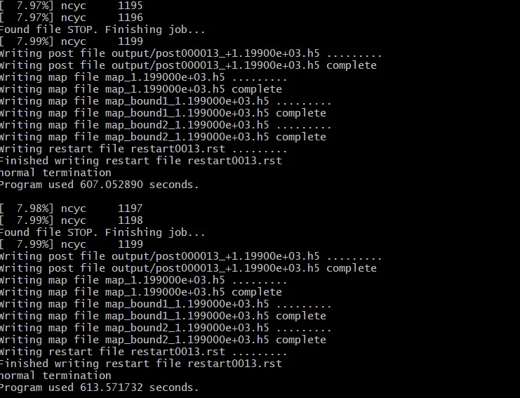
Simulation Results
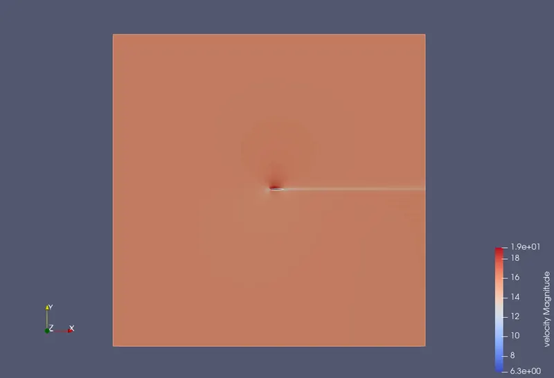
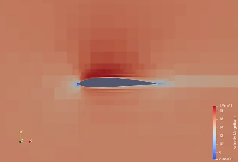
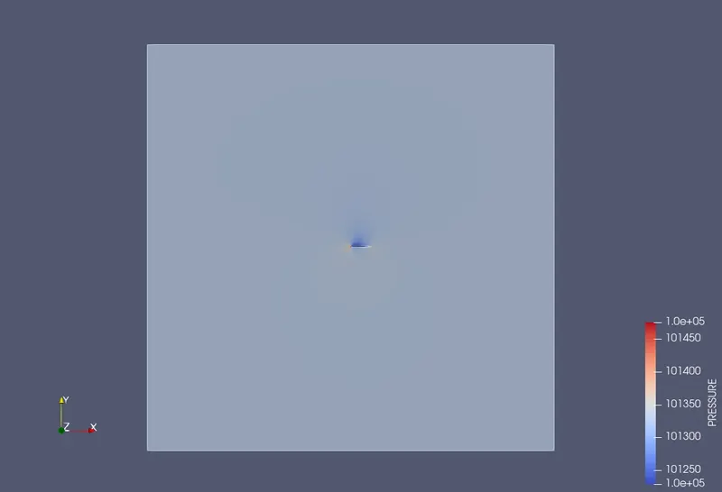
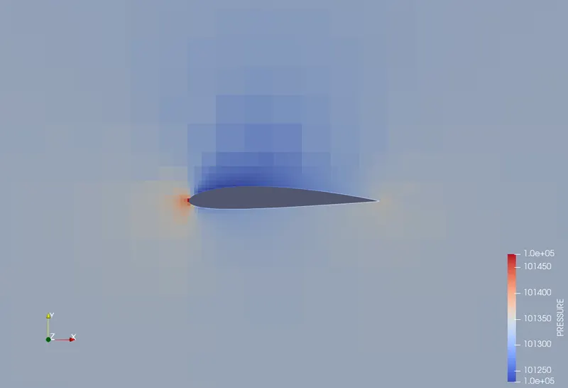
Results images are displayed for the 1 degree angle of attack.
Velocity
Pressure
Streamline
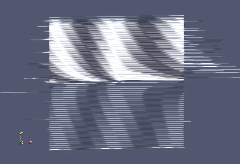
Streamline plot shows the direction of air.
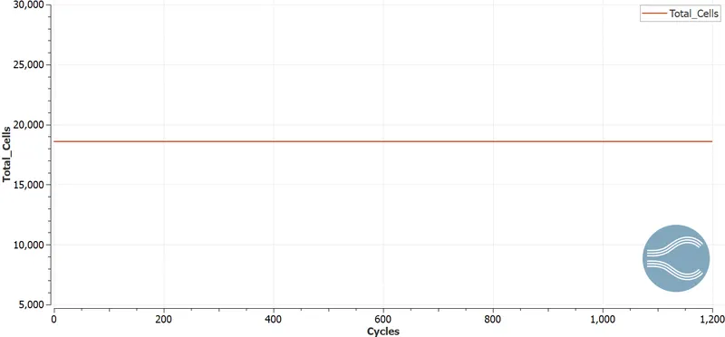
Total Cell Count
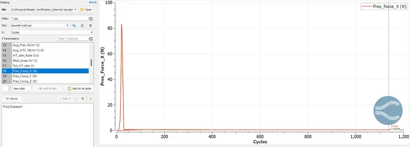
The pressure force graphs will be shown for 2 turbulence model which are kepsilon & k-omega sst models.
Pressure Force in X-Direction using k-epsilon model
Pressure Force in Y-Direction using k-epsilon model
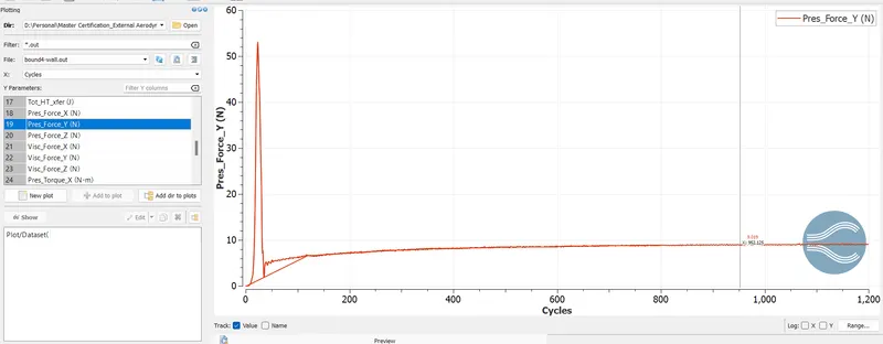
Calculating Drag Force for results obtained through k-epsilon model
Dimensions of the airfoil can be determined using the following image. The dimensions of the bounding box will be used to obtain the dimensions.
To calculate drag & lift cofficient, we will use following nomenclature for analytical method.
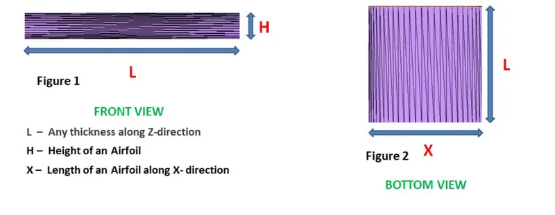
L = 0.2m
H = 0.024m
X = 0.2m
The equation for drag coefficient is as follows:
`C_d = F_d/(0.5*rho*A*v^2)`
But, Converge measures the force per unit length. So, to calculate the drag force in Newton, we are multiplying it with the Length. The area of the structure can be written as Length X Height .
`C_d = ((F_L/L)*L)/(0.5*rho*(L*H)*v^2)`
Above equation will be used to calculate the drag coefficinet.
For Lift Coefficient, the similar approach will be used. The only change is area will be calcualted as Length * X.
`C_l = ((F_l/L)*L)/(0.5*rho*(L*X)*v^2)`
Following table shows the calculated drag coefficient & lift coefficient for k-epsilon model.
| Angle of Attack | Pressure Force in X (Fd) (N) | Drag Coefficinet | Pressure Force in Y (Fl) (N) | Lift Coeffcient |
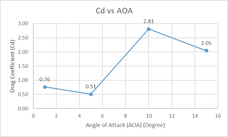
| 1 | 0.54 | 0.76 | 8.9 | 1.51 |
| 5 | 0.36 | 0.51 | 19.45 | 3.29 |
| 10 | 1.99 | 2.81 | 28.18 | 4.77 |
| 15 | 1.45 | 2.05 | 29.36 | 4.97 |
Drag Coefficient vs Angle of Attack
Lift Coefficient vs Angle of Attack
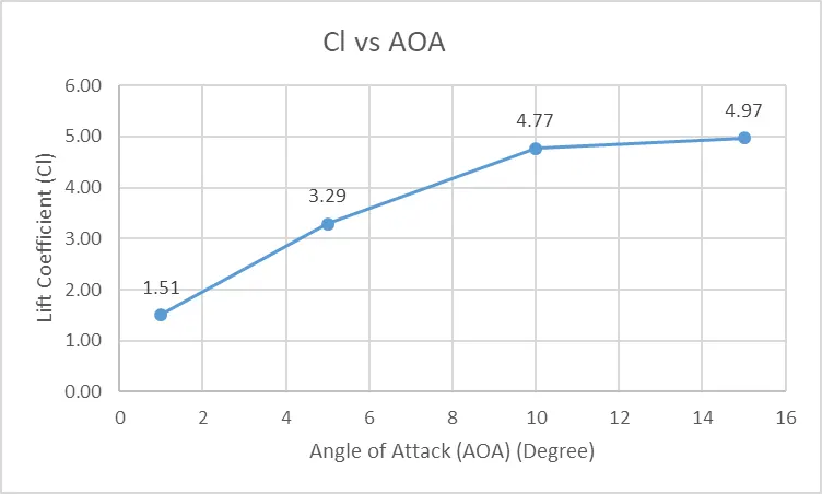
From above graphs, it can be seen that with increase in angle of attack, the drag coefficient & lift coefficient is also increasing. The decrease in drag coefficient of 5 degree angle is unsual, it should not happen.
Comparing Drag Coefficient & Lift Coefficient between k-epsilon & k-omega SST models for two AOA.
| k-epsilon | k-omega SST | |||
| Angle of Attack | Drag Coefficinet | Lift Coeffcient | Drag Coefficient | Lift Coefficient |
| 1 | 0.76 | 1.51 | 1.13 | 1.44 |
| 5 | 0.51 | 3.29 | 0.04 | 3.14 |
While comparing the drag coefficient & lift coefficient computed by two different turbulence model to check the accuracy of different models, the lift coefficient values of k-omega sst model is slightly lower than the k-epsilon model. The same scenario can be seen for drag coefficient for 1 degree angle of attack, but in case of 5 degree, the unsual behavior can be seen here also.