Week 9 - Mini project - Flow over an Airfoil
OBJECTIVE:
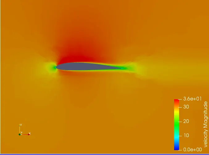
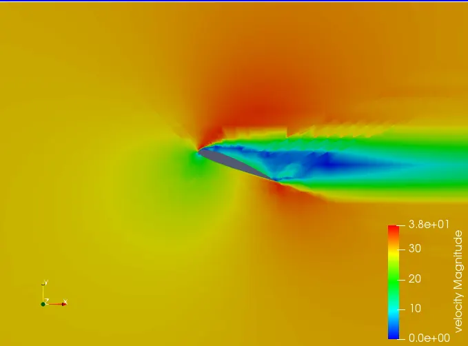
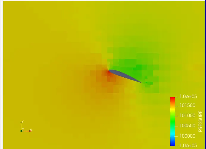
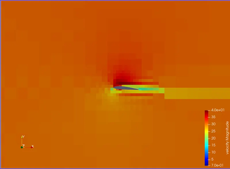
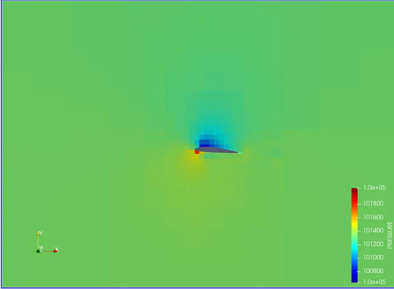
To perform transient simulation over an airfoil, compute the lift and drag coefficients and their variance with AOA and to plot the pressure, velocity contours over the airfoil.
THEORY:
An airfoil is basically a traverse cross section of a body, it's term used to describe the cross-sectional shape of an object, when moved through a fluid such as air, it generates aerodynamic forces. Airfoils are employed on aircraft as wings to produce lift or as propeller blades to produce thrust. Nature interacts with bodies immersed in a fluid mainly through two ways pressure & shear. The components of pressure and shear acting in the perpendicular and parallel to airflow are of concern. Drag acts parallel to the airflow &lift acts perpendicular to the airflow. By simulating flow over an airfoil, the drag and lift co-efficients can be calculated at different angle of attack. The angle of attack is the angle between the oncoming air and the relative line of reference known as the chord line.
Drag force acts parallel to the wind flow and opposes the relative motion of the object. A high drag force is an undesirable phenomenon that can stall an aircraft. Drag Co-efficient, which is normalized using the drag force gives an indication of its aerodynamic hinderance to motion. Drag Co-efficient is calculated as:
Cd= 2Fd/(ρ*V²*A),
Cd is the drag coefficient,
Fd is the drag force
ρ= density of the fluid in which the object is moving
V= freestream velocity
A= Frontal Area of the object
Lift: Lift force acts perpendicular to the wind flow and is what helps to generate lift on an object. Aircraft are designed to generate as much lift as possible whereas cars, on the other hand, are designed in such a way that they produce a negative lift which is known as downforce. This negative lift force helps the car to maintain contact with ground surface even at very high speeds. The lift coefficient is normalized using the lift force formula:
Cl= 2L/(ρ*V²*A),
Cl is the lift co-efficient
L is the lift force
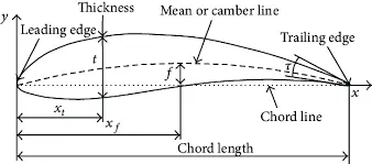
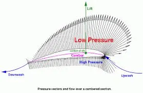
Diagrams showing important airfoil features, and the pressure regions.
The Coanda effect describes the tendency of a jet to follow the contours of an adjacent boundary even when this boundary curves away from the initial jet axis. This effect either arises due to a) the pressure gradient perpendicular to a curved streamline, or b) differential entrainment and the development of a partial vacuum.
In the first case it may be shown using the Euler equation (or the Bernoulli Equation in an incompressible fluid) that a curved streamtube experiences a net force towards the center of curvature. Since no component of the viscous force acts perpendicular to a streamtube, this implies that P1 > P2. It is this pressure gradient that causes the jet to be deflected from its initial axis, and accounts for the so-called Coanda effect.
Alternatively, if a jet is discharged in the vicinity of a solid boundary, the entrainment of fluid into the jet will be restricted on one side (A). This creates a partial vacuum so that Pa < Pb, and consequently the jet attaches to the flow boundary.This effect is particularly apparent in 2-D jets.
SETUP:
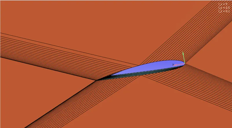
|
Application Type |
Time-based |
|
MATERIALS: |
|
|
1. Gas simulation |
Standard |
|
2. Global Transport Parameters |
Standard |
|
4. Reaction Mechanism |
1. fluid: O2 and N2 |
|
SOLUTION PARAMETERS |
|
|
1. Run Parameters |
Transient >Full hydrodynamic>Compressible |
|
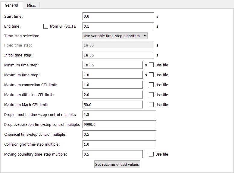
2. Simulation time parameters |
|
|
3. Solver parameters |
Navis-stokes solver scheme: PISO Navis-stokes solver type: density-based |
|
BOUNDARY CONDITIONS |
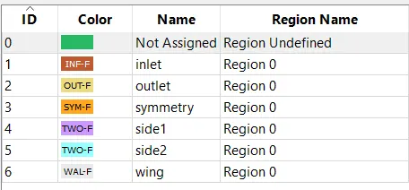 |
|
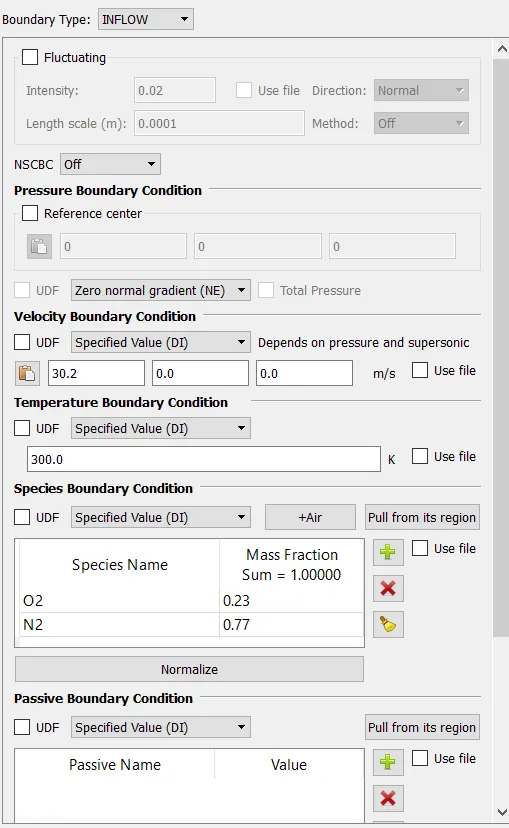
1. Inlet |
`Re = 200000 = (rho*v*L)/mu` Where - `rho` is air density `v` is air velocity `L` is the characteristic length, chord length in our case. `mu` is the dynamic viscosity of Air. 2) `v = (Re*mu)/(rho*L) = (200000*1.85e-5)/(1.225*0.01)= 30.2`m/s |
| 2. Outlet | 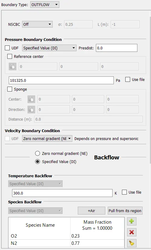 |
|
3. Symmetry |
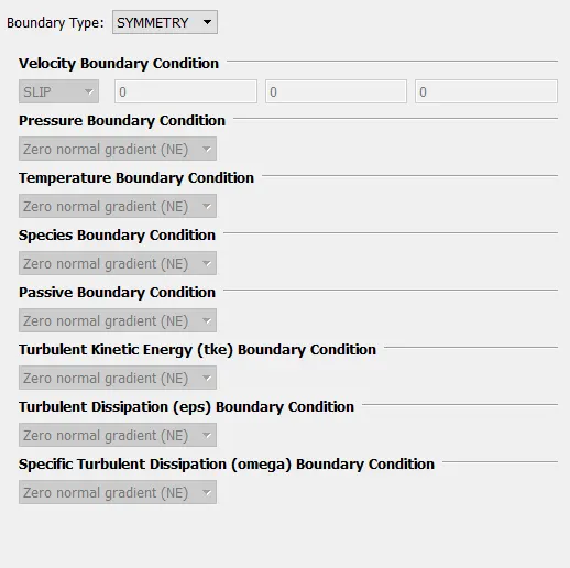 |
|
4. Sidewall 1 |
2D wall |
|
5. Sidewall 2 |
2D wall |
|
6.Wing |
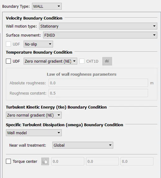 |
|
INITIAL CONDITIONS AND EVENTS |
|
|
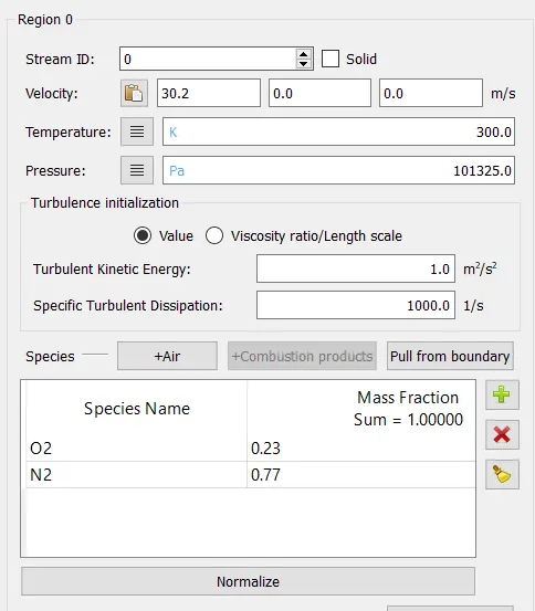
1. Regions and initialization |
|
|
PHYSICAL MODELS |
|
|
1 Turbulence modeling |
k-omega SST |
|
GRID CONTROL |
|
|
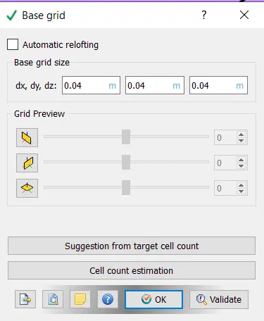
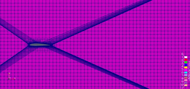
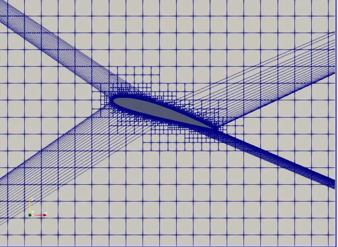
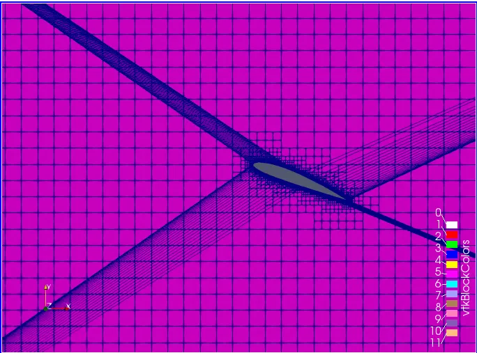
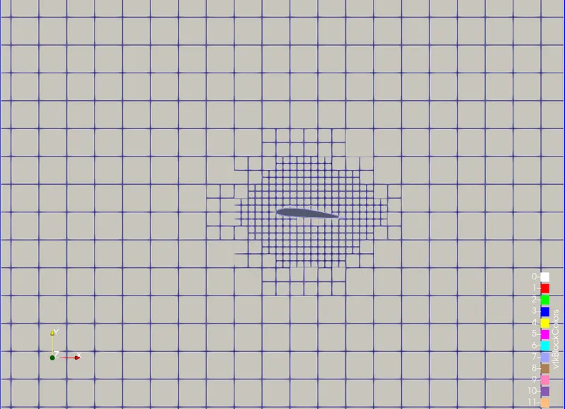
1. Base mesh |
|
|
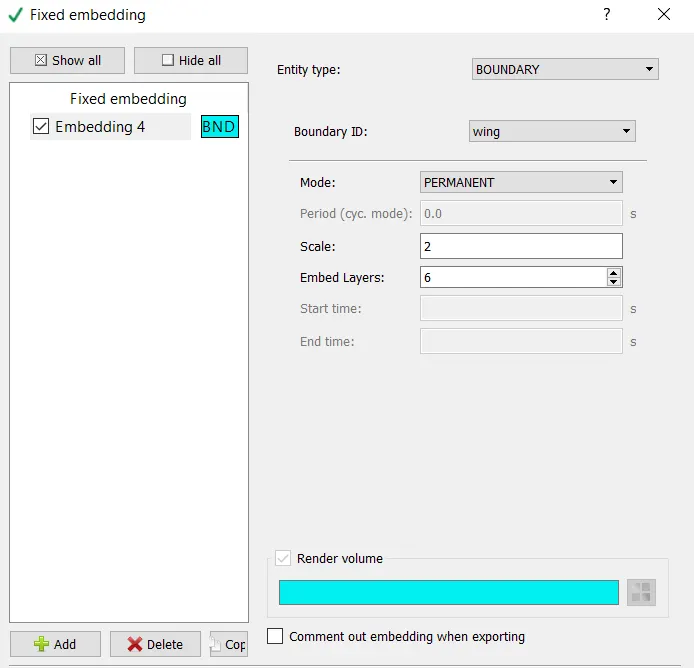
2. Fixed meshing |
|
|
OUTPUT/POST-PROCESSING |
|
|
1. Post variable selection |
Standard |
|
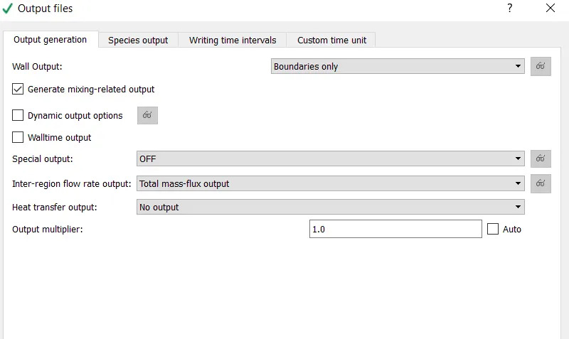
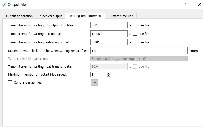
2. Output files: |
|
RESULTS:
AOA-1
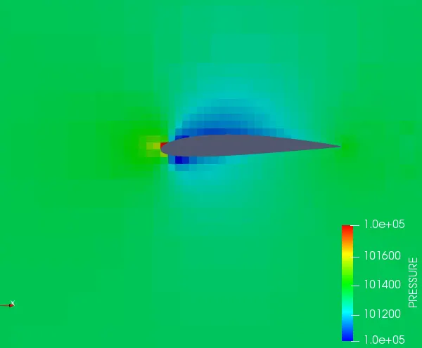
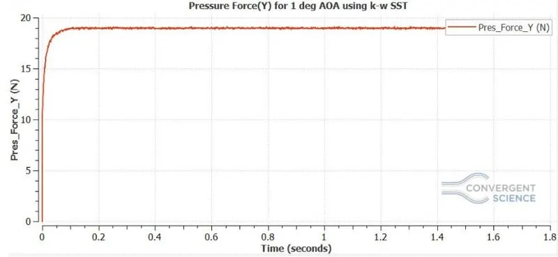
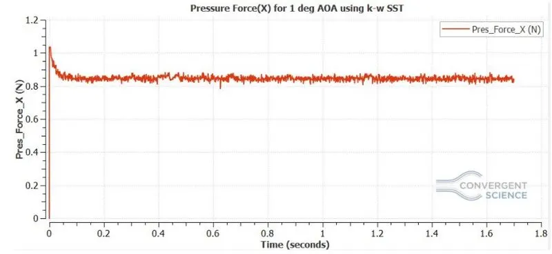
AOA 10
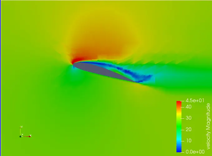
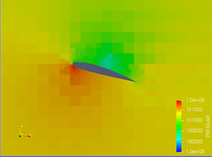
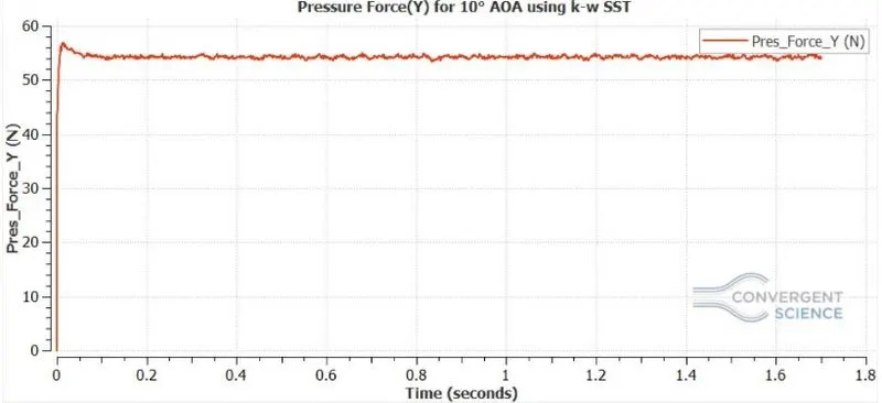
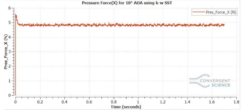
AOA 15
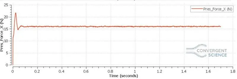
AOA 5
CALCULATION & TABLE:
- Using the formulas mention in the theory we calculate
- The lift coefficient , `C_l=(F_l)/(0.5*rho*V^2*A_p)`
here, `F_l`is the lift force is given below, where
`A_p` is the area of the frontal projection. (0.1m)
Similarly the drag coefficient is given by: `C_d=(F_d)/(0.5*rho*V^2*A_p)`
Here `F_d`is the drag force is given below.
-
`rho` is air density
`v` is air velocity 30.2 m/s ( for the given reynolds number)
`L` is the characteristic length, chord length in our case.
`mu` is the dynamic viscosity of Air.
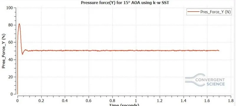
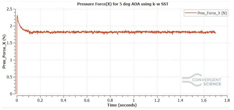
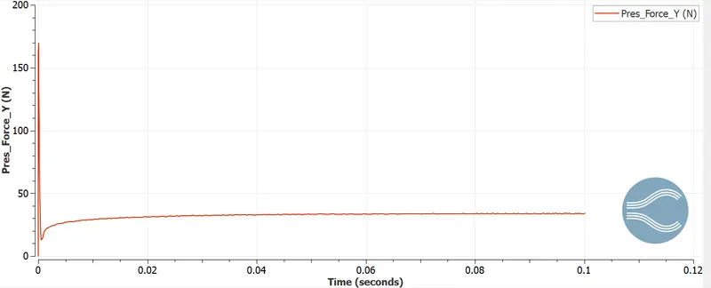
- The force values used in the table are average values of the forces, from the plot. The coefficients are bascially quantified method of potraying the lift and drag over the body.
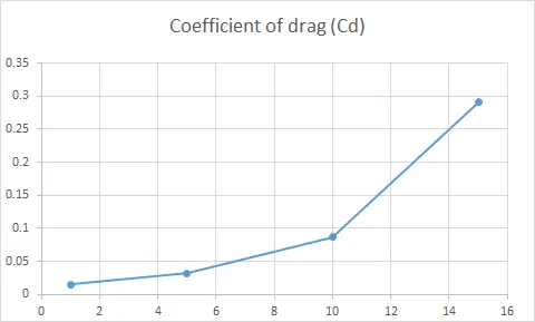
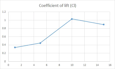
| AOA | Drag force (Fd) | Lift force (Fl) | Coefficient of drag (Cd) | Coefficient of lift (Cl) |
| 1 | 0.85 | 19 | 0.0152 | 0.3401 |
| 5 | 1.8 | 25 | 0.03222 | 0.4475 |
| 10 | 4.85 | 57.5 | 0.08682 | 1.0293 |
| 15 | 16.23 | 50 | 0.29053 | 0.89505 |
CONCLUSIONS:
1. We can see from the plots, that lift increases with angle of attack and after a particular angle of attack, the lift significantly drops, this is called stalling condition.
2. The drag on a airfoil is primarily skin friction at low angles of attack, as the AOA increases the the predominant drag is the pressure drag, because of flow seperation and wake formation at the aft of the airfoil, beacuse of which the total drag increases.
3. Only in certain AOA the aerodynamic characteristics of the airfoil is preffered i.e between 1-10 AOA, for our case.