Week 9 Machining with Planer Challenge
INTRODUCTION:
- A planer is a type of metalworking machine tool that uses linear relative motion between the workpiece and a single-point cutting tool to cut the work piece. A planer is similar to a shaper, but larger, and with workpiece moving, whereas in a shaper the cutting tool moves.
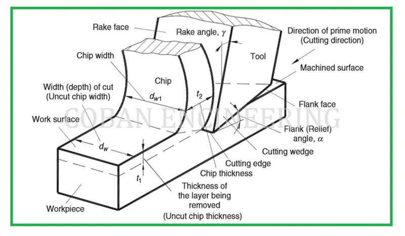
Planning operation geometry
PROCEDURE:
- Open the ANSYS Workbench software. Under the Analysis system select the Explicit dynamics and wait for few seconds to pop up the window, which contains Engineering data, Geometry, Model, setup, Solution and Results.
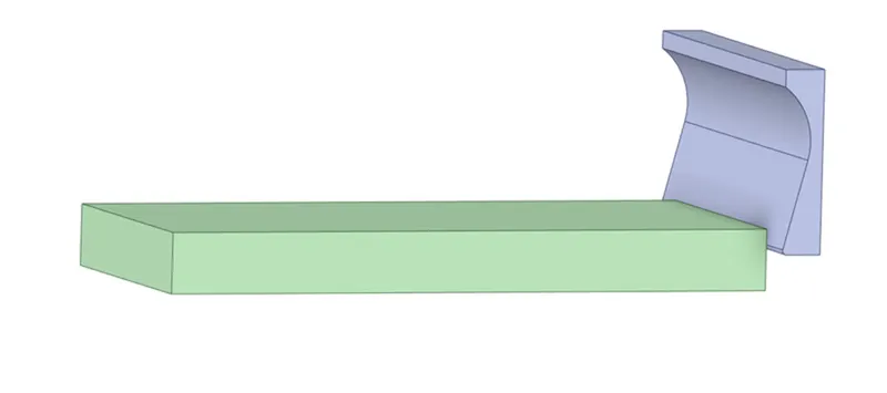
- Under geometry import the Machining with Planer model.
- Update the model by right click and edit the Model for Preprocessing.
- Wait for few seconds and ANSYS Mechanical will open as shown below. Rename the model as work piece and cutting tool.
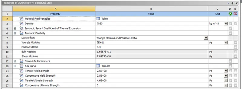
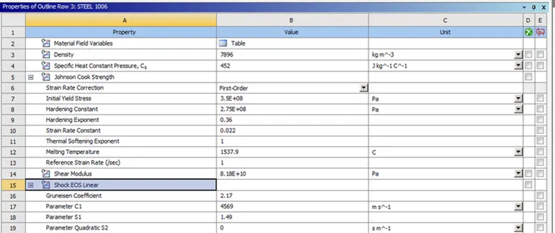
- Assign the materialto the model. Default we have structural steel l.and assign Steel 1006 material to the workpiece, by selecting the material under Explicit materials and make tool behavior as rigid.
Material properties:
- Contacts- In this model we have a default bonded contact. So delete that bonded contact and under body interactions make sure that the body interaction type as frictionless.
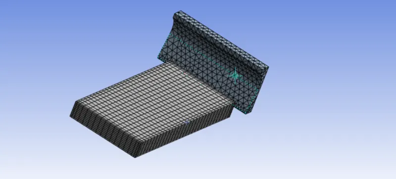
- In ANSYS automatic mesh will be performed with Default mesh size and so insert the method and select the tool, change the method as tetrahedranes. Select the sizing option and select the four edges as shown below and assign the no. of division as 10. Then generate mesh
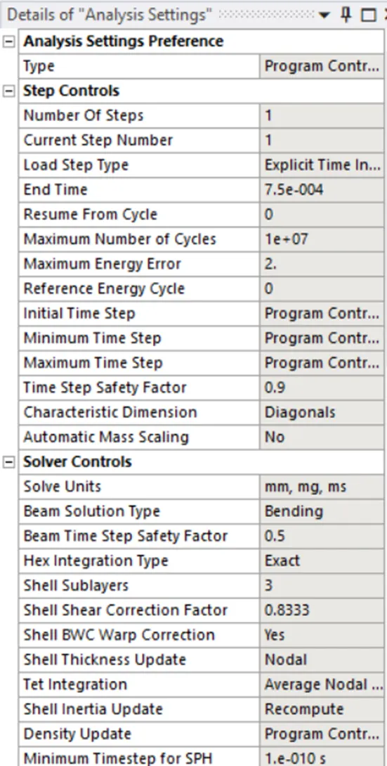
- Analysis settings, end time as 7.5e-4, maximum energy as 2 and remaining settings are default.
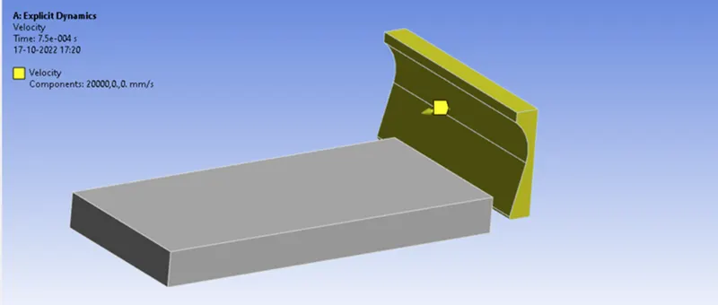
- Insert a velocity select the cutting tool and assign the values as shown below.
For Case-1: X=20000mm/s, Y=0 and Z=0.
For Case-2: X=15000mm/s, Y=0 and Z=0.
- Insert a fixed support to the work piece and select the face as shown below.
- Now request for the outputs such as equivalent stress, equivalent elastic strain, directional deformation in x-Direction, total deformation, equivalent plastic strain and User defined result temperature of the body.
SIMULATION RESULT:
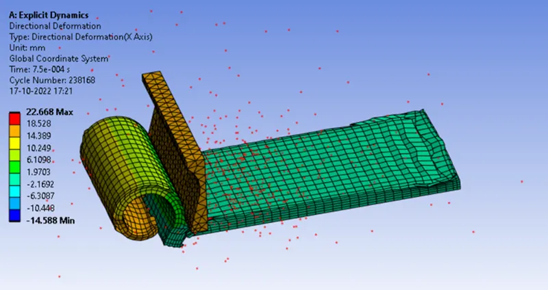
CASE-1: With a velocity of 20000mm/s.
- Directional Deformation:
- Temperature-
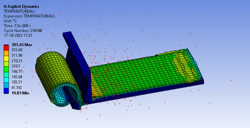
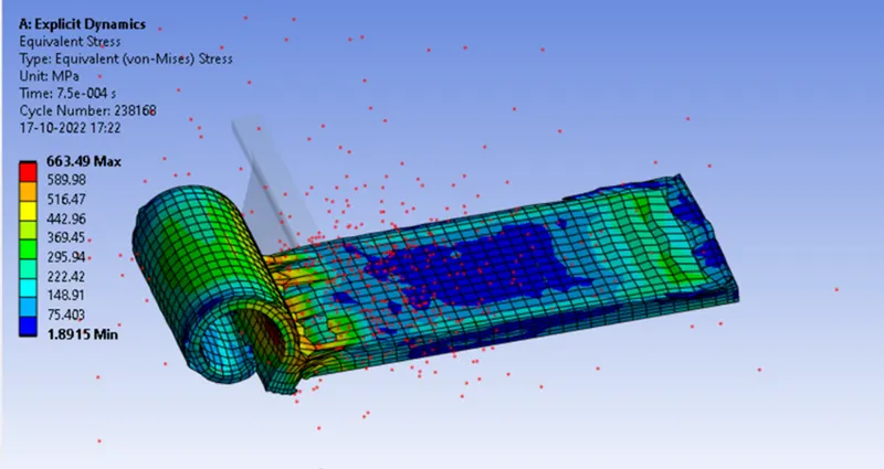
- Equivalent stress:
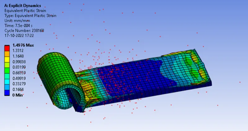
- Equivalent Plastic strain-
- Camparison of results:
Parametric Study

CONCLUSION:
- From the above result we can conclude that the Maximum equivalent stress of 663.49MPa is experienced in case-1 and Maximum equivalent stress of 666.82MPa is experienced in case-2. So the change in velocity will not effect the stress values so much. The Max temperature of 395.43°C is experienced in case-1 and the Max temperature of 346.08°C is experienced in case-2. The Max Total Deformation of 22.668mm is experienced in case-1 and the Max Total Deformation of 37.251mm is experienced in case-2. So finally we conclude that case-1 will have smooth and good surface finish than the case-2. By this we can say that the if velocity is higher then we get smooth and good surface finish.